Overview
The test stand
was designed to measure the static thrust produced by a water
rocket. It is based on a single point load-cell
connected to a load cell amplifier and the
amplifier in turn is connected to a data logger.
The data is captured through a laptop.
Load Cell
The load cell used in this stand is a 70kg load
cell from a
Chinese manufacturer whose cost
and delivery were far cheaper than local
distributors. Purchase price was
US$24
+ $9 delivery. Delivery was around 8 days.
The 70Kg load cell is a good
compromise between the upper and lower
ranges of thrusts for regular water rockets. Data Logger
The data logger used is from DATAQ.
The
DI-148U
was chosen as it already had a
USB connection. The
DI-194RS
is a cheaper serial port alternative. The logger
was ordered through a local
distributor called
Total Turnkey Solutions (www.turnkey-solutions.com.au).
All up delivered the DI-148U Starter Kit was AU$118. Load Cell
Amplifier
The data logger reads in
the -10V to 10V range with a 10-bit accuracy. The load cell only
produces millivolts over the entire
deflection range which is too low for the
data logger to get enough resolution
directly. The
amplifier basically converts these small
voltage changes to a voltage over the full
dynamic range of
the logger. It also provides the necessary
excitation voltage for the load cell.
You can buy these off-the-shelf but you will
pay upwards of $100. Being on a limited
budget, we decided to build our own. The
amplifier is based on an
instrument amplifier IC
INA125P. The circuit is
relatively straight forward and these IC's
are designed for exactly this task.
Because it is not easily sourced within Australia, we
ordered them from Texas Instruments in the
US.
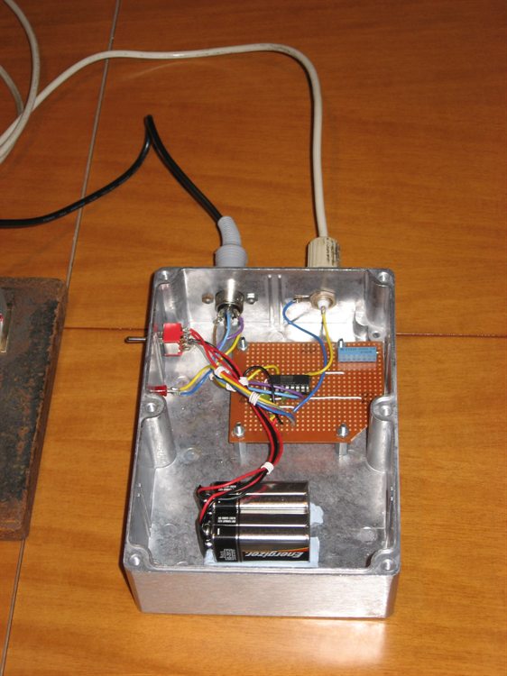
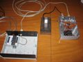 |
Data-logger, load cell and load cell amplifier. |
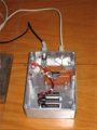 |
The load cell amplifier is housed in a metal box
to reduce noise. |
The load cell amplifier is located close to the load
cell and enclosed in a metal
box. Coax cable is used for the long
run to the data logger. The noise level is down to
around 0.02V over the -9V to 9V range.
On the 70Kg load cell this allows one to
resolve down to ~5 grams. This means we can get thrust
measurement accuracy down to about 0.05
Newtons. The expected thrust range
of most rockets under test will be about
30N to 150N. That range applies for our
typical rockets with pressures of around
120psi with nozzles under 10mm. The same
setup will also be used for full bore tests
of up to around 600N.
Circuit Diagram
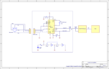 You can adjust the
amplifier's gain using the multi-turn trim
pot in order to get the
required thrust range. Because we use
two 9V
batteries as the power source we don't quite
get the full +/-10V range, but it is close
enough. The excitation voltage used for the
load cell is 5V. Parts List
Since this was going to be a one-off we
didn't bother with a PCB and just built the
circuit on a strip board.
|
Part |
Designation |
Quantity |
Source |
|
INA 125P Instrument Amp |
U1 |
1 |
Texas
Instruments |
|
16 Pin IC socket |
- |
1 |
Jaycar |
|
50 ohm
Coax Connector |
JP2 |
1 |
Jaycar |
| 5
DIN socket |
JP1 |
1 |
Jaycar |
|
DPDT switch |
S1 |
1 |
Jaycar |
|
Power LED |
LED1 |
1 |
Jaycar |
|
500 Ohm multi turn pot |
R1 |
1 |
Jaycar |
|
1.5KOhm |
R2 |
1 |
Jaycar |
|
0.1uF Capacitor |
C1, C2 |
2 |
Jaycar |
|
9V battery |
B1,B2 |
2 |
Jaycar |
|
9V battery clip |
- |
2 |
Jaycar |
|
Metal enclosure |
- |
1 |
Jaycar |
Software
The data logger came with free "lite"
software for capturing and viewing the data.
However, being free there are some
limitations in terms of exporting the data
and maximum allowed sample rate. The max
sample rate is 240Hz which is more than
ample for us. The full software with higher
allowed sample rates (14,400 samples/sec) is
another $200. You can also buy a $99
software add-on that lets you save the
captured data into Excel friendly format.
The free software, however, does record the data into their own
proprietary binary file format. A
software
application was written to read this data and convert it to
thrust curves. Test Stand
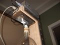
At the top of the test stand the load
cell is bolted to a heavy steel plate which
in turn is bolted to the stand. Above that
is the load cell amplifier. The entire
rocket is just suspended from the load cell.
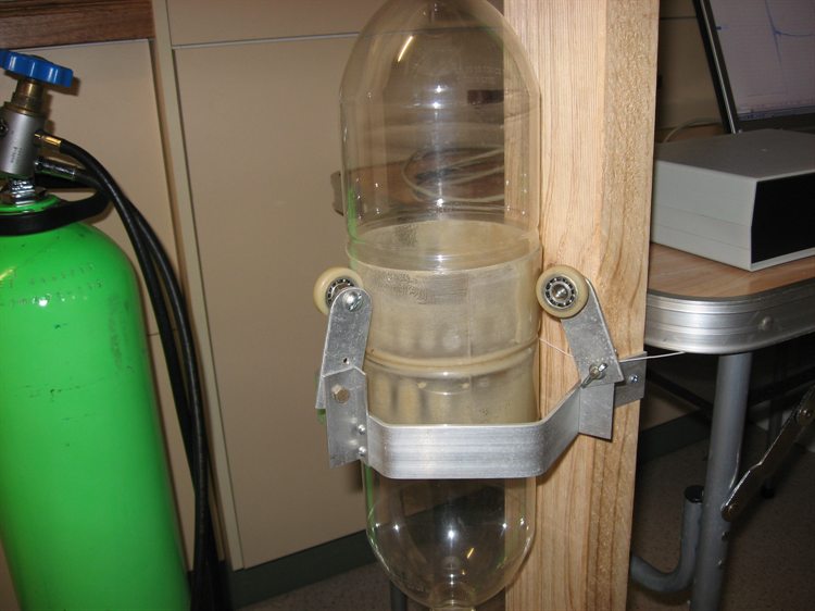
The arrangement at the bottom of the test
stand stops the rocket moving side to side
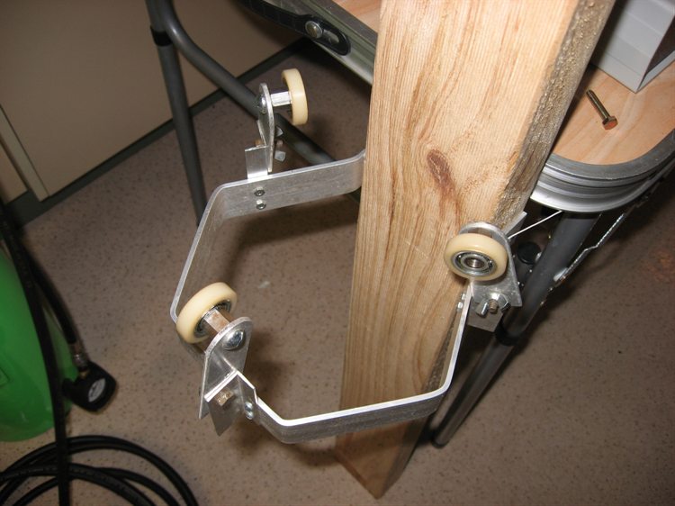
when thrusting. It consists of 3 adjustable
wheels on ball bearings that allow them to
be brought closer together for narrower
rockets and further apart for wider
rockets. The rocket only lightly touches
these (a few mm clearance) so there is
essentially no friction between them and the
rocket during the test.
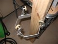
The rocket under test can be quickly
disconnected from the load cell with the
single pin that goes through the
bracket connected to the load cell. This
lets us take the rocket off, fill it with
water and re-attach it back to the load
cell.
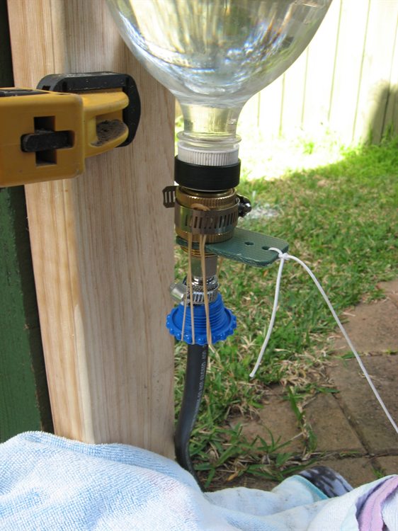
The release mechanism
consists of a brass Gardena mechanism with
the spring removed and rubber bands are used
to provide a retracting force. We added a
non-return valve inside the release head as
well as a hose quick connect adaptor to the
bottom. We use a thick piece of plastic with
a string attached wedged under the collar.
To release the nozzle we simply pull on the
string and the whole mechanism falls away.
The total cost of the test stand not
including the laptop was about AUD$230.
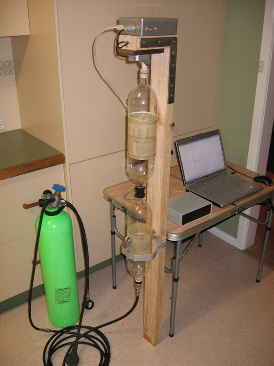
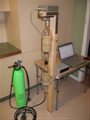 |
Complete test stand setup with load cell,
logger, laptop and support framework. |
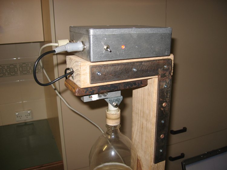
 |
The amplifier is mounted on
top ... |
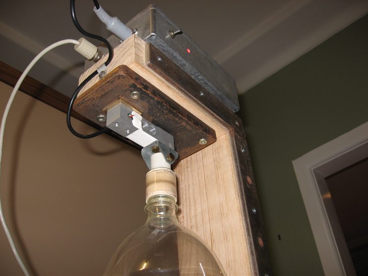
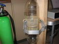
 |
... with the load cell
underneath. The bottle is connected to the load cell
here. |
 |
The rocket is supported by
three wheels that barely touch it. This allows the
rocket to move with very little friction. |
 |
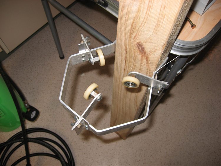
The wheels can be adjusted
out or ... |
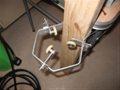 |
... in depending on the size
of the rocket. |
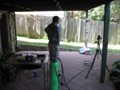 |
First tests set up outside.
|
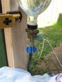 |
Nozzle release head. Pulling
the string causes the release head to drop away. |
References
The original source of the article is from
Air Command Water Rockets website here:
The following references were used in the
construction of this test stand.
Other sources of load
cells, amplifiers and loggers we looked at:
|