Introduction
The deployment timer is intended to be used on water rockets
to provide a delay after launch to release the parachute. The
design is based on a simple two stage timer. After launch is
detected, the first timer waits the deploy delay time before
triggering the second timer. The second timer determines for how
long the deploy actuator (motor) runs.
The timing delays can be set for both the deploy and the
motor by changing the value of the corresponding potentiometers.
With the values shown, one can set the deploy delay between
about 0.5 - 11 seconds, and the actuator delay from ~0.1 to ~2
seconds. If the delays need to be set outside these ranges, then
the R3,C2 and R5,C4 components can be substituted. The Time
delay of each timer is calculated by:
T (sec) = 1.1 x R x C
(R is in ohms and C is in farads)
To trigger the first timer one can either push the Launch
Detect button momentarily, or it may remain held down. For a
practical rocket, one should set up an arrangement that makes
this connection instead of the switch when it launches. For
example: spring loaded electrical contacts with a piece of paper
or plastic between them. The piece of plastic is attached to the
launcher and when the rocket is launched it gets pulled out from
between the contacts and to make the necessary connection.
The power supply can be anything between 5V and 12V so it
should work with a wide range of batteries. A 6V battery is
recommended. The motor driver part of the circuit can drive a 3
- 6V DC motor at currents up to about 500mA for brief amounts of
time. Higher currents will need to be supplied by larger
batteries.
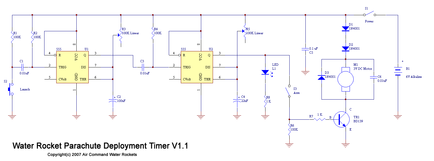
Circuit diagram
See the circuit diagram at left.
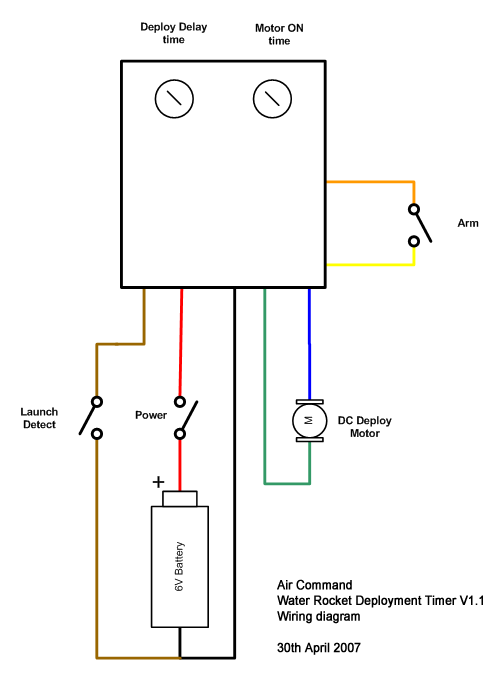
Wiring Diagram
The timer should be wired according to the
wiring diagram
shown on the left.
Operation
Because it is a fairly simple circuit, one needs to make sure
the "Arm" button is in the OFF position when power is turned ON.
This is because the timers can come up in any state and run
through the deploy cycle once. After about a 10-12 second delay
it is safe to turn the Arm button to the ON position. The Arm
button should be kept in the OFF position to prevent accidental
deploys while still filling and adjusting the rocket on the pad.
Just before launch the Arm switch should be set to ON.
Setting Delays
Before launching the deploy delay and motor delay trimpots
need to be adjusted for the correct timing. The motor delay
should only need to be set once and will depend on the
deployment system, motor and gearbox used. Enough time should be
given to the motor to fully operate the mechanism it needs to do
the deploy.
The deploy delay is likely to need changing between launches
and therefore the trimpot should be accesible from the outside
of the rocket perhaps through a small hole using a screwdriver.
The best way to calculate the approximate deploy delay is to use
one of the online simulators and enter the rockets parameters
and launch pressures to establish an approximation how long the
rocket will take to get to apogee. The delay can then be set
based on this value. On subsequent launches this delay can be
adjusted to suit. When setting this value, you will need a stop
watch to measure the exact time.
- Set the Arm switch to the OFF position.
- Turn timer on
- Adjust the trimpot half way.
- Activate the launch detect switch, and using the
stopwatch, time how long it takes before the LED turns on.
- Adjust the trimpot and repeat step 4. until the desired
deploy delay time is set.
The timer can be safely turned off with the correct delays
being set next time the timer is turned on.
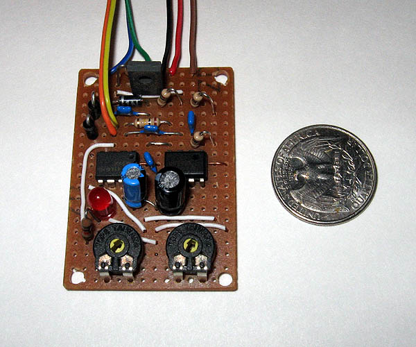
Water Rocket Parachute deployment timer
It is possible that the trimpots can become misadjusted due
to jarring on landing, so the time delays should be verified
before each launch.
|