This is the continuation build log of our
previous rocket project called "The
Shadow". The log is in chronological
order so to see the most recent post you
need to Jump To The Bottom.
You may need to refresh this page to see any
latest updates.
CAUTION: If you are going to
attempt to build rockets such as these,
please exercise extreme care when testing
and flying them. This rocket uses high
pressures that can potentially cause severe
injury to yourself and those around you.
Always double check your equipment and
review safety procedures before every test
and flight. See more information on
Safety Guidelines.
Build Log
14 February 2012
- Spent some time looking for the cause
of the deployment mechanism failure. See the
"what went wrong?" section in the
Day 115
flight report for more details. At this
stage we will most likely try an alternative
way of ejecting the parachute, though we
haven't made any decisions yet.
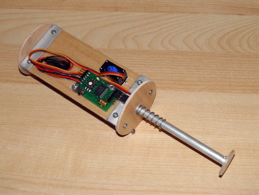
Deployment mechanism as it came
out
of the ground.
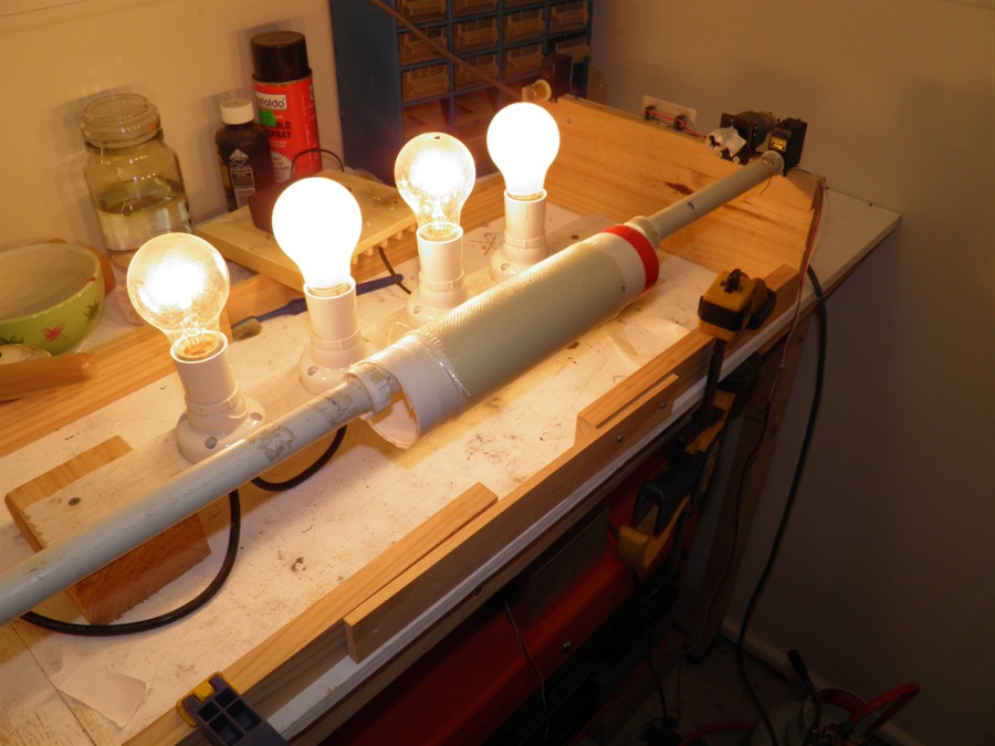
Testing the servo timer and
servo.
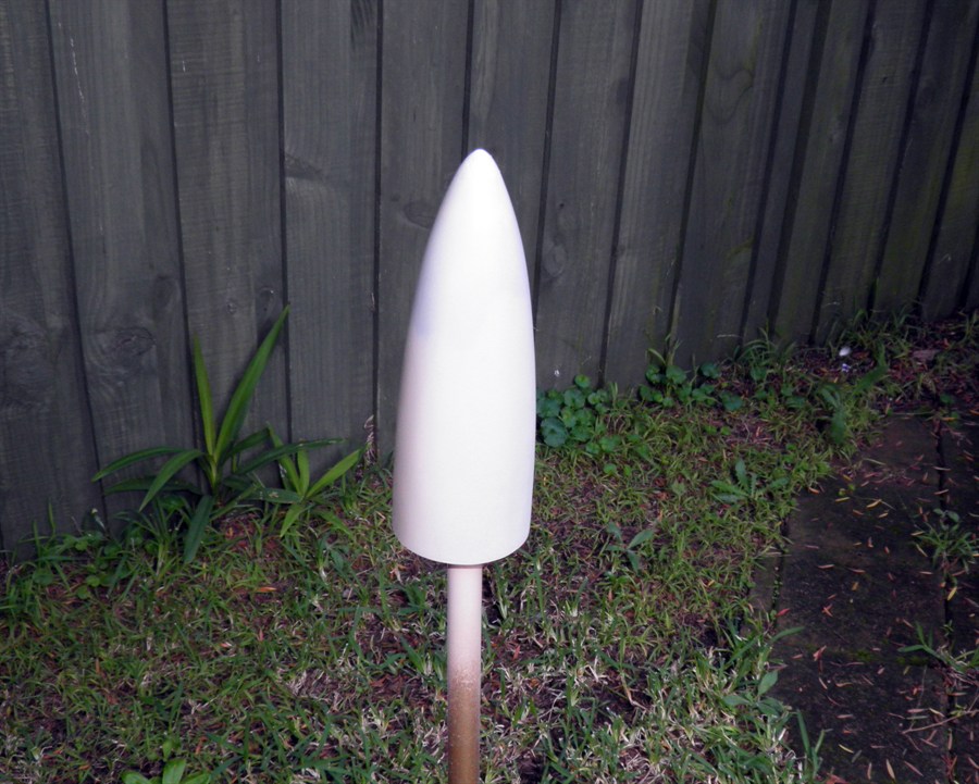
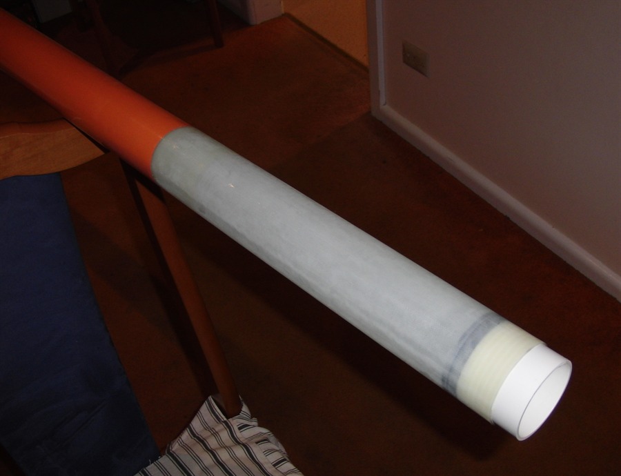
16 February 2012
- We mixed up some detergent and water
and poured it into the aft end of the rocket
and swirled it around so that all the walls
were coated and lubricated. We then pushed
the nozzle back into place with a 2m long
wooden pole. The integrity of the seal will
need to be re-checked in a pressure test.
Before ...
Nozzle pushed back into place
14 April 2012
- After a bit of a break from rockets, we
started repairing the Shadow again. We recovered what components we could
from the debris. There were actually quite a
few we could re-use. We straightened out the
lever arm as well as the deployment
mechanism end brackets. Really only the
balsa wood components and the piston needed
to be replaced. All the fasteners, springs
etc were still usable. We already had spare
balsa wood sandwiches made from before so it
was an easy task to just cut out the
required components.
16 April 2012 -
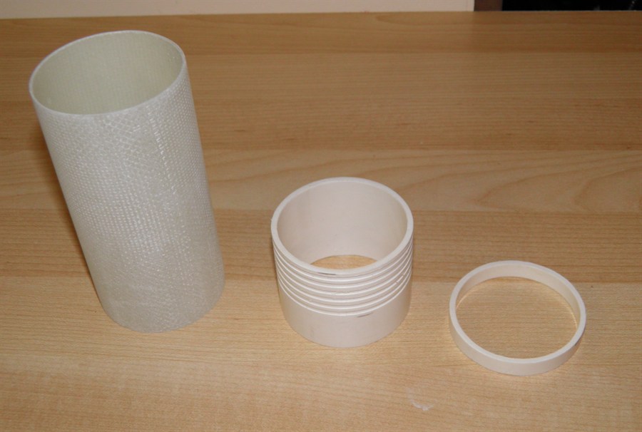
A busy day. We trimmed the end of the
damaged body tube and cut it square. Only
about 12cm of the end of the body tube was
damaged. We then took one of the couplers we
made earlier that was a little tight and
sanded it until it fit in the body tube.
The we took a piece of the 60mm PVC and machined a new retainer ring
with grooves for the glue. Having made one
earlier and having the tech drawings to go
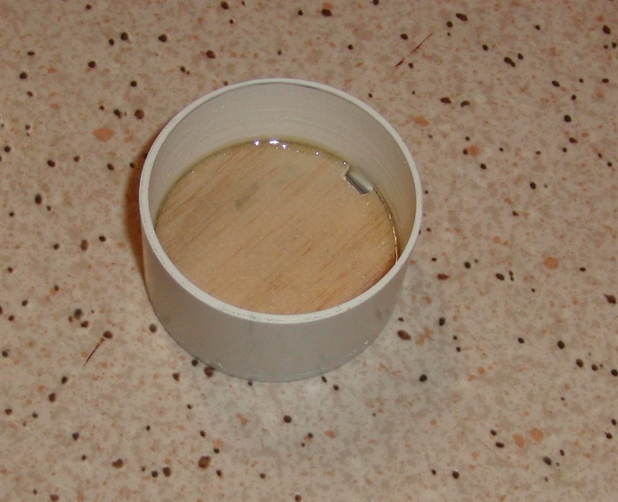
with it made it so much easier. We cleaned
the end plug as it had dirt on it from the
impact. Thankfully this was intact without
any damage. This is a critical component and
is made to tight tolerances.
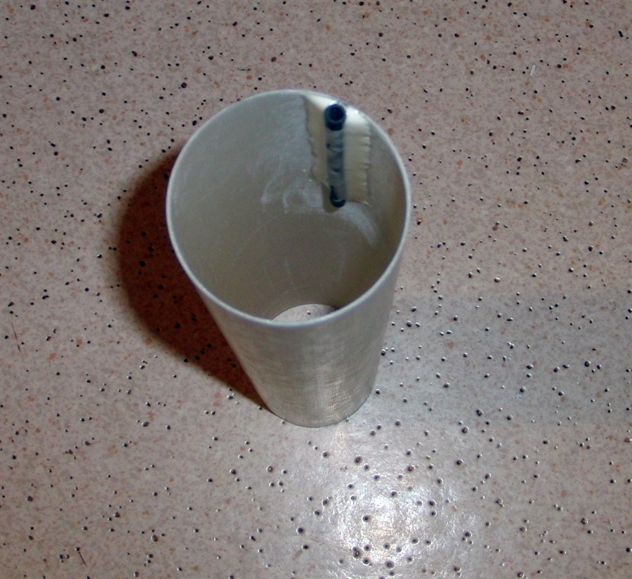
We made another piston guide for the
ejection mechanism. These are just made from
old aluminium knitting needles. They
telescope well into the aluminium tubing we
use for the piston. We epoxy a small machine
screw into the end of it so we can mount it
easily.
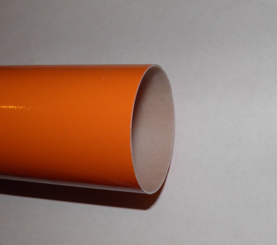
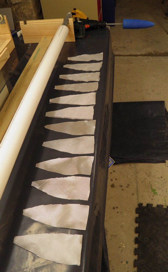
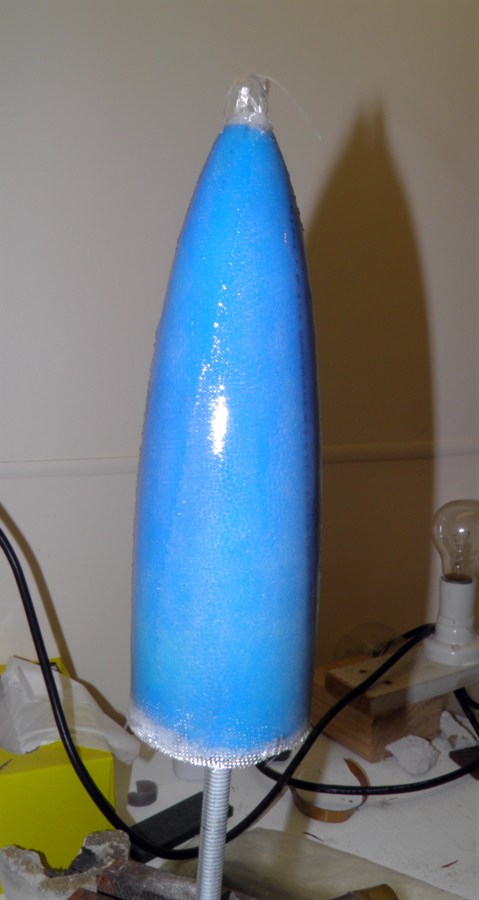
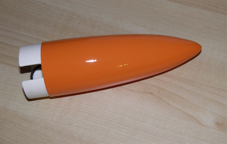
In the afternoon we made a new nosecone
using 6 x 200gsm and 6 x
85gsm cloth gores. We spaced them out more
evenly this time which gave a more uniform
wall thickness.
We also machined a new deployment mechanism
support ring from PVC that the entire
deployment assembly rests on.
End of the damaged body tube has
been
trimmed.
New coupler, and retaining
rings.
Fiberglass gores ready to make
up a new nosecone
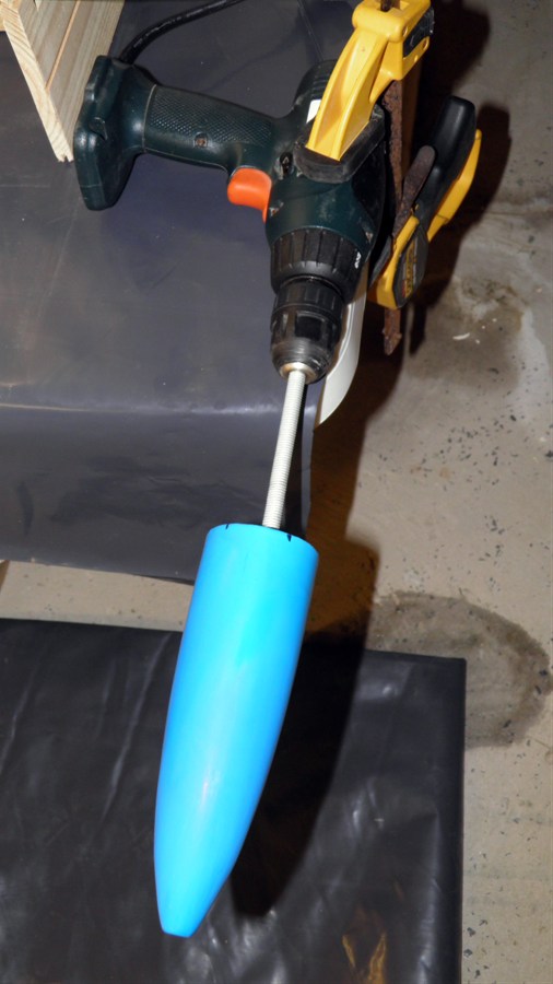
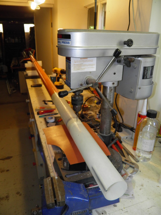
Nosecone plug mounted in the
chuck of a cordless drill to
make
it easy to turn by hand as the
glass is applied.
All layed up and waiting
for the epoxy to cure.
17 April 2012
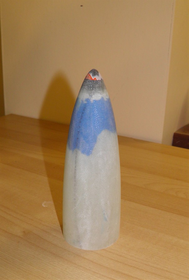
- We took the nosecone off the plug today.
It came off very easily due to the three
layers of balloons with silicone grease
between them, but the outer most balloon did
not want to come away from the fiberglass
very easily at all. The rubber looked like
it bonded well with the epoxy. I'm not sure
why that is, but the problem did not occur
last time. We removed most of it except in
the top third where it really doesn't
matter.
We then sanded the whole nosecone with
coarse sandpaper. I always find it easier
sanding it under a running tap as you don't
get the dust and it washes the dust from the
sandpaper.
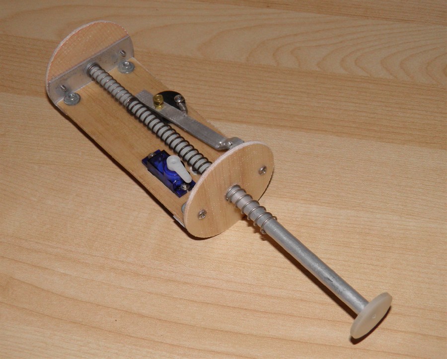
We attached the straightened-out end brackets
to a new piece of balsa sandwich.
Straightened brackets mounted to
the a new
balsa sandwich.
Nosecone removed from the plug.
The blue is some balloon left
stuck inside.
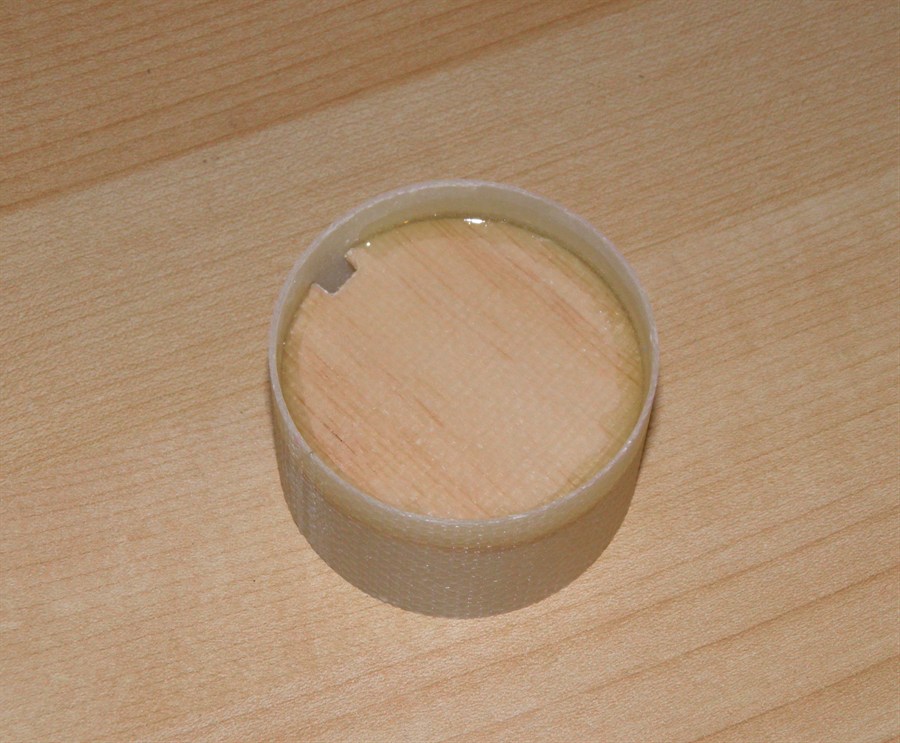
18 April 2012
- Today we glued in the nosecone tip which
we recovered undamaged from the previous
nosecone. We also epoxied the locking ring
on ejection piston tube. The lever arm locks
against this ring. We glued the bulkhead
into the nosecone coupler.
Nosecone coupler.
19 April 2012
- We made the bulkheads for deployment mechanism
today. They were just cut from the balsa
sandwich.
New bulkheads attached to the
mechanism
The ejection piston still needs
to be cut to length.
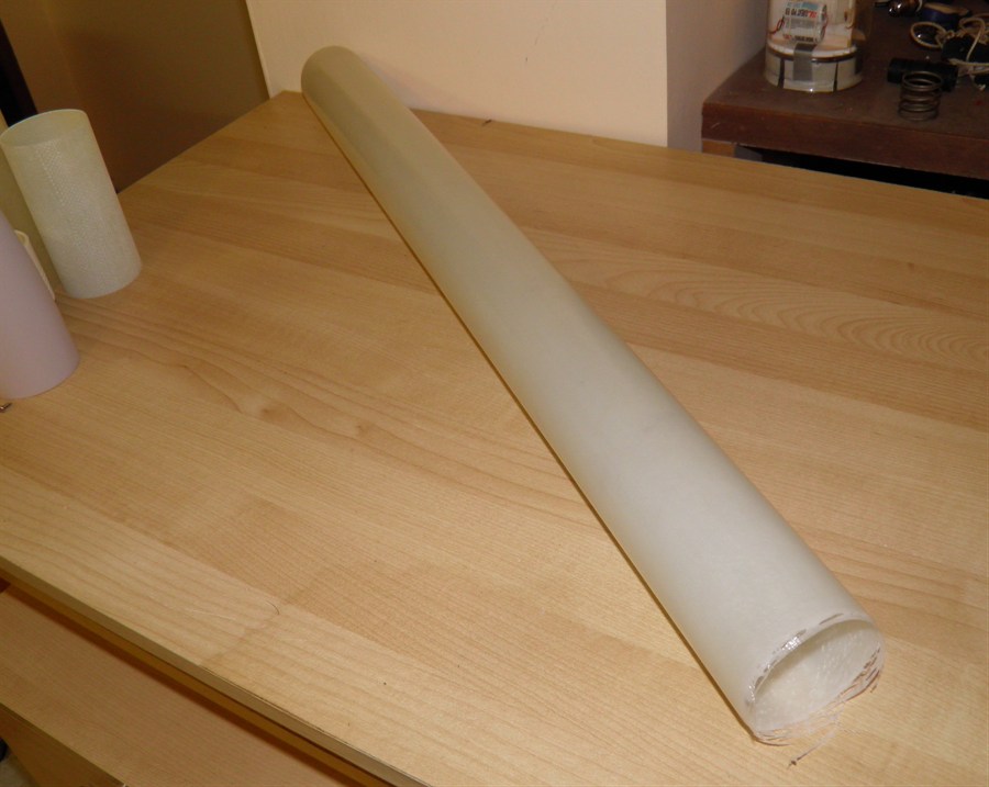
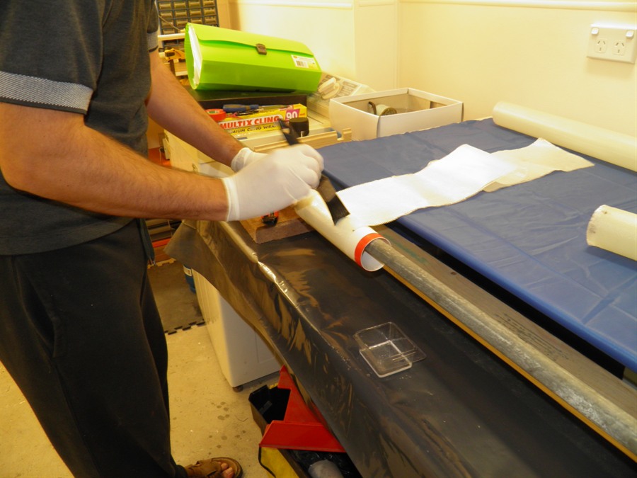
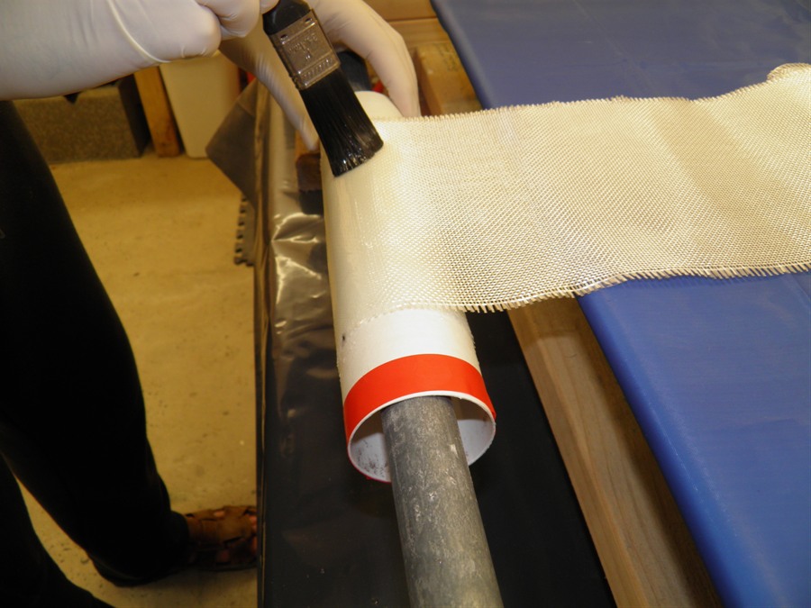
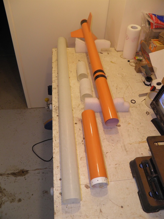
21 April 2012
- Made a new fiberglass body tube
approximately 700mm long. Part of this tube
will be the payload section and the other
will be the pressure chamber body. Although
the payload bay tube may be a little heavier
than needed because it is not pressurised, it was just easier to make both
of them at the same time. After we rolled
the tube and had it on the rotisserie for a
while, we dry brushed the surface to remove
little bubbles that sometimes form from the
roller. This makes for a much smoother tube
and less sanding.
The nosecone was sprayed with filler putty
and the nosecone bulkhead was made and glued
into the nosecone coupler.
Laying up a new body tube.
Baking on the rotisserie.
Spray painting the nosecone with
putty.
22 April 2012
- The servo motor and STII were attached the
deployment mechanism. We machined
a new ejector plate adaptor for the piston
as this was also damaged in the crash.
Servo and STII mounted.
Piston cut to length with
Ejector plate adaptor.
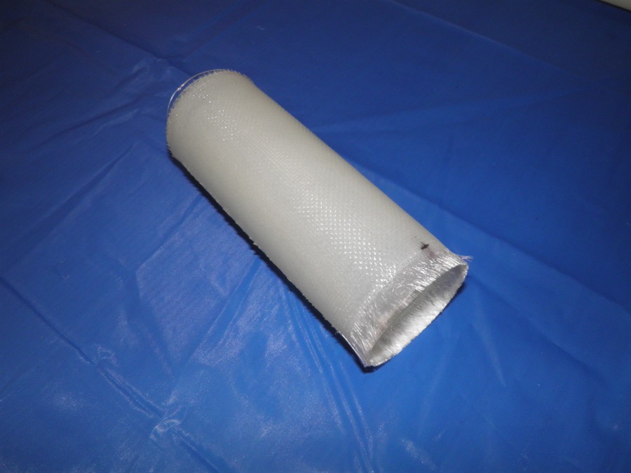
New tube removed from mandrel.
24 April 2012
- Today we sanded and trimming the body tube
and cut it to
length. We also decided to use one of the
existing couplers that we made earlier but
was a little over size. We just sanded it
back down until it fit snugly. The coupler
was glued into the pressure chamber.
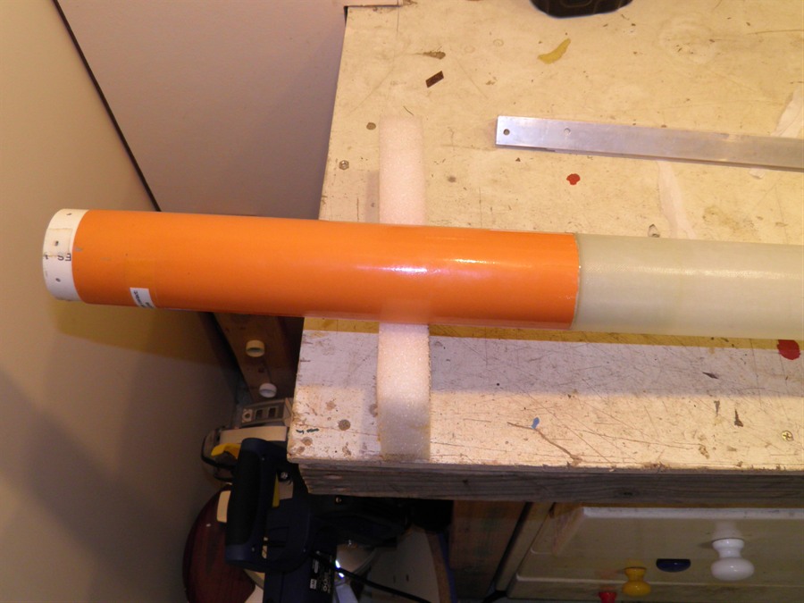
11th June 2012 -
Today we glued the body tube extension
onto the pressure chamber. We also looked at
how easily the nosecone coupler could slide
out of the payload bay tube and it was
sticking a little, The fiberglass on
fiberglass friction is fairly high and if
you angled the nose a little it would wedge,
So this time we are going to make the
coupler from the PVC pipe that we use for
the mandrel. Because the PVC is thicker than
it needs to be we machined out the center of
it to make it lighter. This way we also made
a small shoulder for the bulkhead to rest
against. It seems like it slides better in
the payload bay tube.
18th June 2012
- The end plug was glued in with the
retaining ring today. We always use a little
soapy water to get the o-ring to slide into
the tube rather than silicone grease because
we don't want any of the grease on the
bonding surface. We then thoroughly dry and
sand the bonding surface before applying the
epoxy. We also made and attached the
nosecone bulkhead into the nosecone coupler.
And lastly we glued the CF tube into the
payload bay tube that will be the main
attachment point for the parachute.
Pressure chamber extension and
end plug glued in place.
CF tube attached to payload bay.
New PVC coupler and glued
bulkhead.
19th June 2012
- Today we attached the ejection
mechanism to payload bay with 6 screws. The
screws attach the payload bay through the
PVC ring at the base of the mechanism.
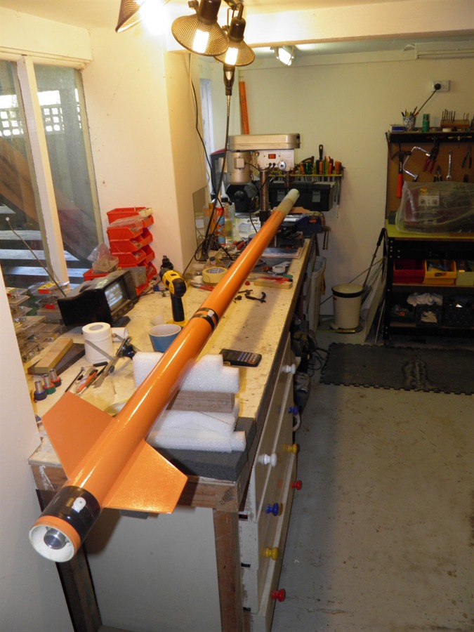
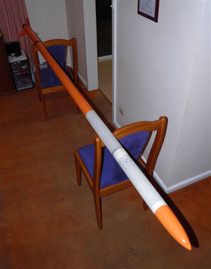
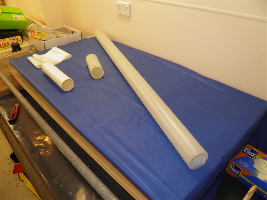
Drilling holes for payload bay.
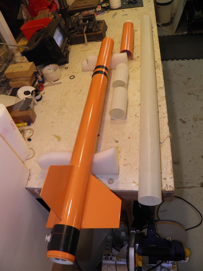
The rocket just fits onto the
bench
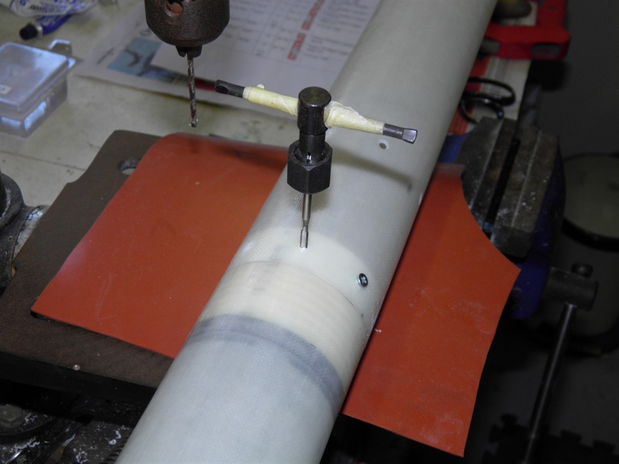
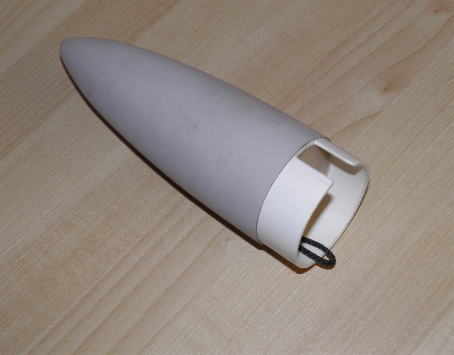
20th June 2012
- We cut slot in nosecone coupler to
make room for the CF tube and glue. The
nosecone was also painted. The payload bay
was also attached to the pressure chamber by
drilling and tapping 8 holes in the retainer
ring.
Tapping 8 holes for the screws
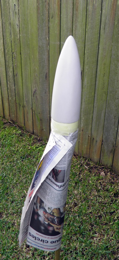
Nosecone with glued in coupler.
Ready for painting
Final coat of paint.
23rd June 2012
- Today we started working on the
payload bay framework. This framework sits
right up against the pressure chamber and
below the parachute ejection mechanism.
We also did the first parachute ejection
tests with the new mechanism. The first two
test went fine with plenty of power ejecting
the parachutes, but on the third attempt the
nosecone was wedged at an angle and did not
deploy. This would have been resulted in a
crash. I carefully removed the nosecone to
see why and it was caused by the parachute
being packed long and thin. The bottom of
the parachute was on one side, while the top
of the parachute was pushing against the
other side of the nosecone. This may be in
fact what happened during the crash.
So I repacked the parachute to be short
squat and round to more evenly distribute
the load and the next few tests were fine.
We will test it quite a few more times
before the launch to make sure that this
different packing technique is fine.
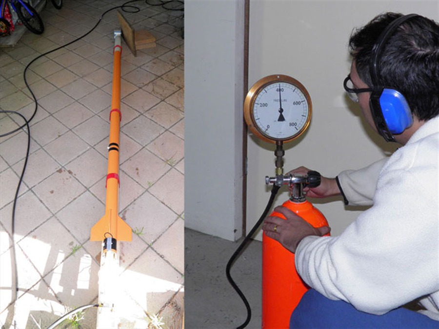
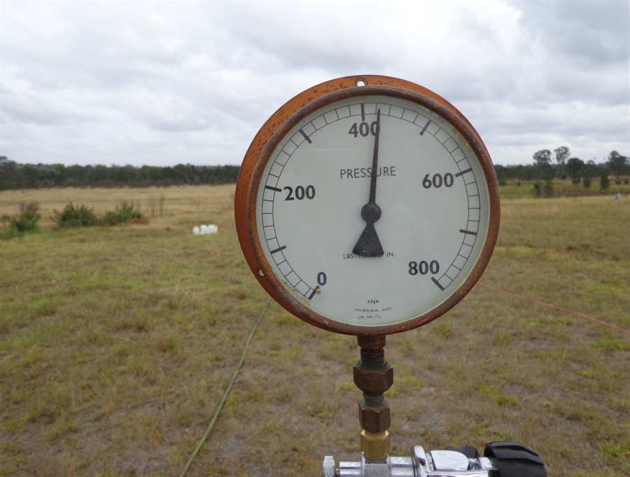
24th June 2012
- Today we did a hydro pressure test of
the rocket's pressure chamber. We were happy
that it held 400psi (27.5 bar) This will be
the target launch pressure for the next
launch. The test also showed that the lower
part of original pressure chamber was
undamaged during the crash. The nozzle
bulkhead that had moved half way down during
the crash was also okay and the o-ring seal
was undamaged.
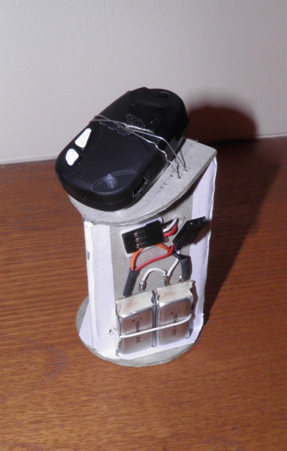
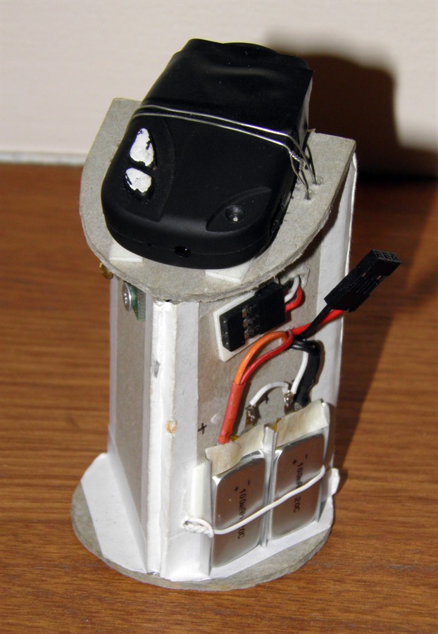
We also finished making most of the
payload bay framework that holds the
batteries, camera, and altimeter.
Hydro pressure test to 400psi.
Payload framework. The camera
buttons are painted white for
easier
viewing inside the rocket body.
26th June 2012
- Drilled out the holes to access all
the components inside the rocket, The
payload bay tube now looks like Swiss
cheese. We also ran a number of simulations
to figure out how much of a delay to set on
the timer.
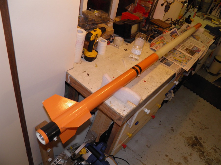
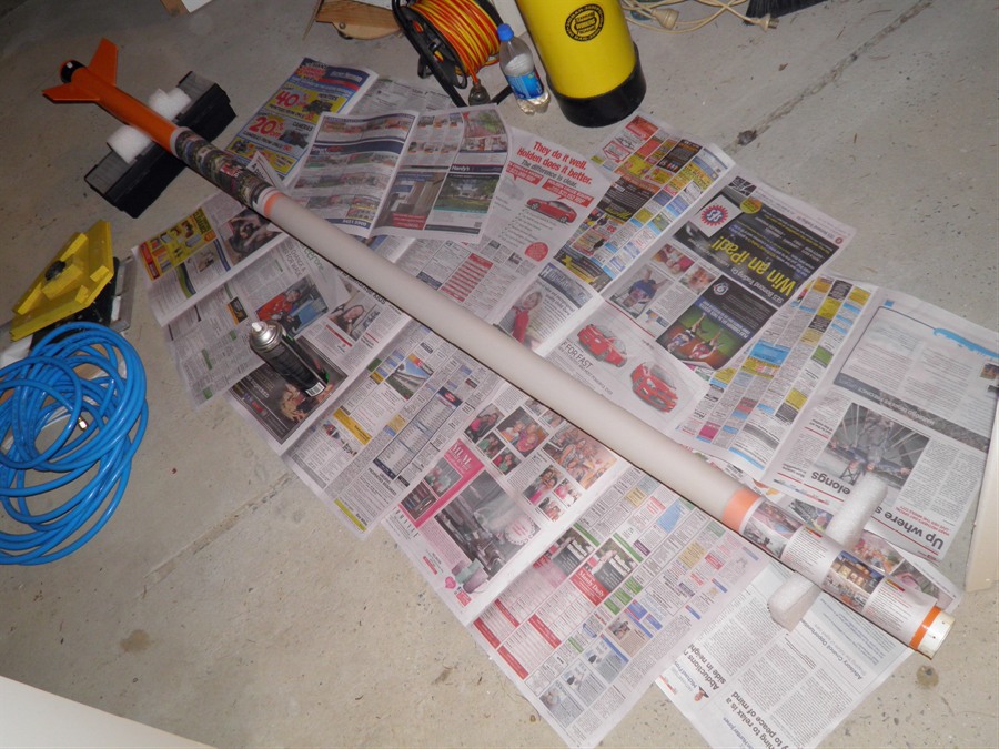
Rocket assembled.
27th June 2012
- Painted the undercoat on the payload bay
as well as the pressure chamber extension.
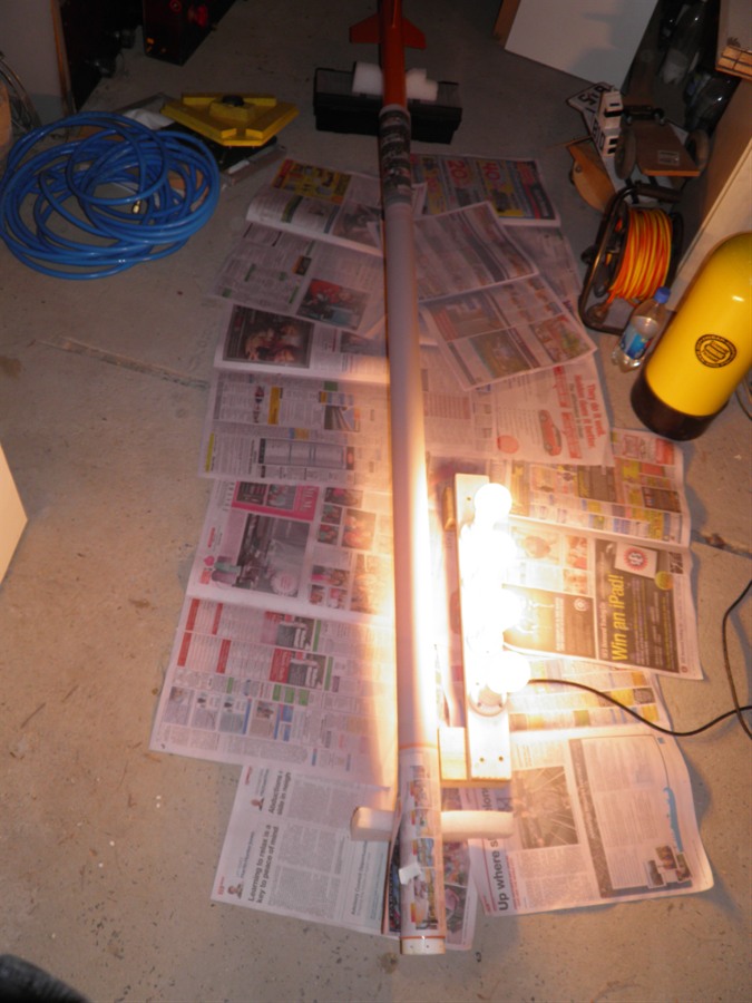
28th June 2012
- We painted the rocket in the afternoon
and had to sit it in front of the heater for
most of the night so that it would dry by
the next day. This paint normally takes
about 4 or 5 days to dry completely.
29th June 2012
- Final preparation and testing of the
ejection mechanism. It was discovered that
the nosecone to got wedged again. We added
about 1cm of padding in the nosecone to
allow the piston to have a shorter travel
and sanding the PVC coupler allowed the
system to eject the parachute cleaner. the
#16 HD camera had also packed it in, so we
had to replace it with the #11 as that was
the only one we had spare.
Final payload bay components.
Final ejection mechanism
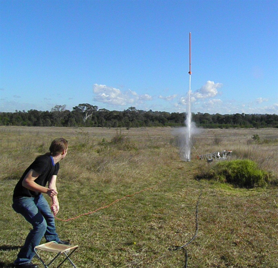
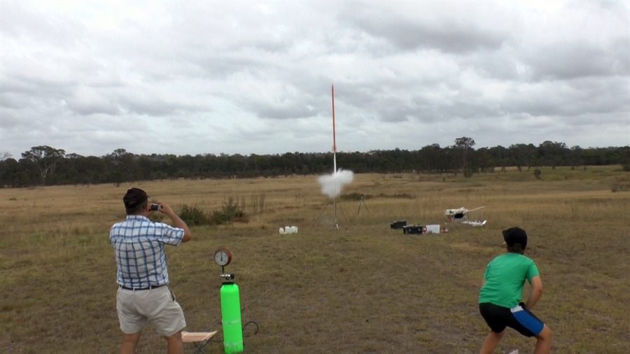
30th June 2012
- Launch day. We had a great day launching
the rocket today. Here is the
full flight report from
the day. The rocket flew twice, once at
400psi and again at 420psi. It flew to an
altitude of 1173 feet on the first flight
and to 1239 feet on the second flight.
First flight
Stills taken from video
of launch
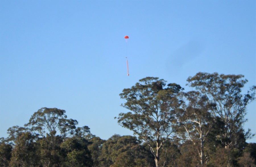
Second flight
Landing.
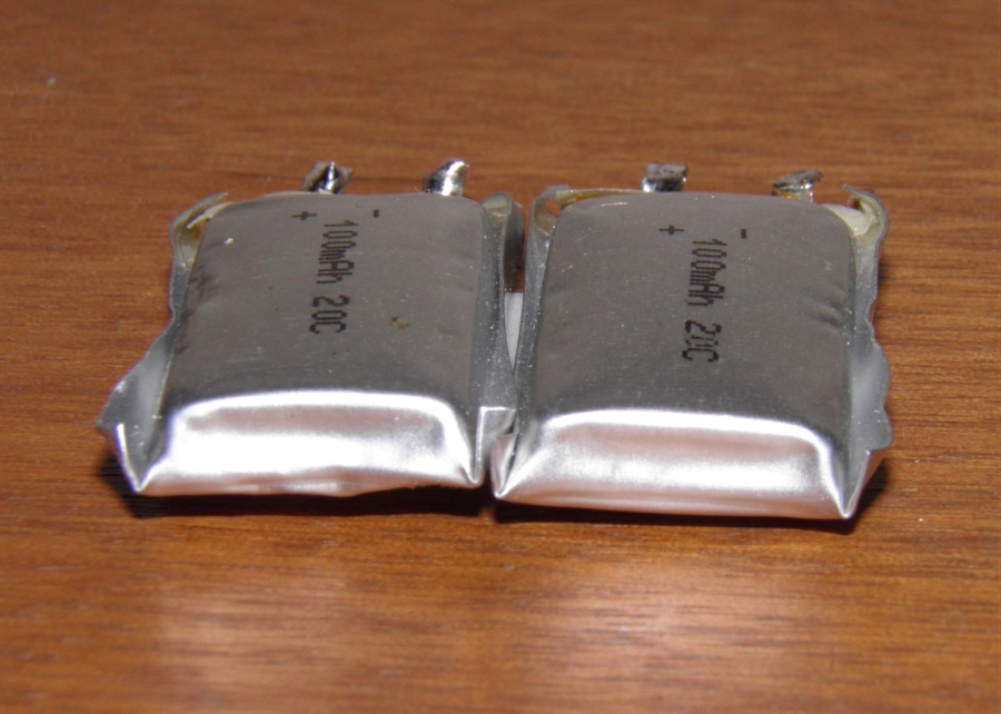
5th
January 2013 - Today we replaced the two
LiPo batteries in the payload section. A
couple of months ago I had accidentally left
the power on to the altimeter which
completely drained them to 0V. They also
puffed up a bit so we replaced them with a
fresh pair.
Puffed up LiPo batteries
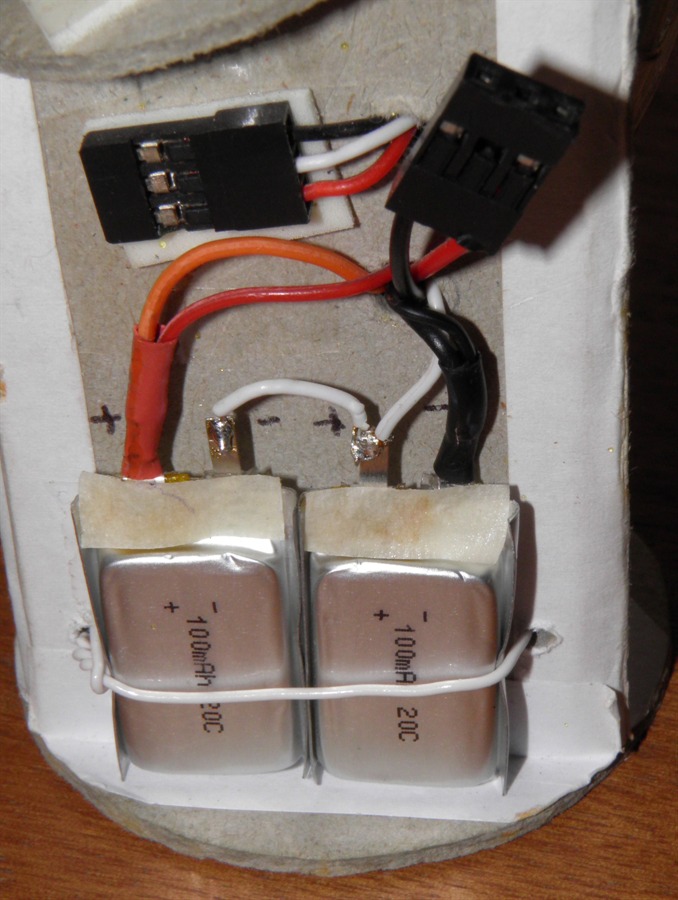
Replaced with new pair
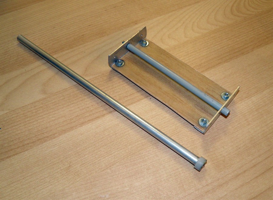
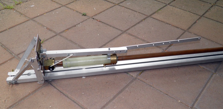
6th
January 2013 - We made a couple of
launcher improvements today. The first was
to add a lever extension to the release arm.
After a couple of difficult launches to
get off the pad, with this extension we are
hoping things will be easier. We have also
made a new base plate that the whole
launcher attaches to so that it makes it
easier to swap on launch day with our
regular release mechanism. The new plate
just slides into place and is bolted down.
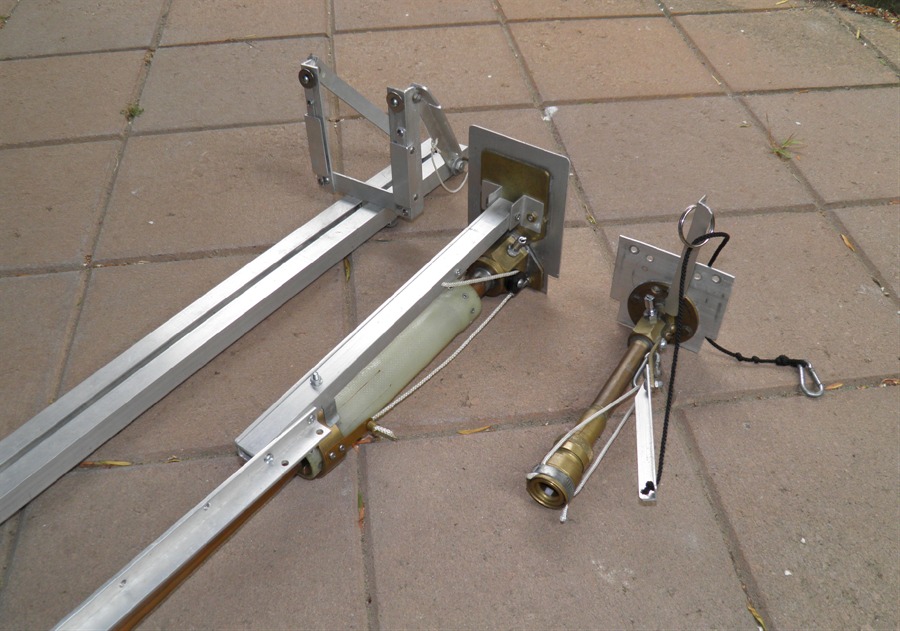
Because the base plate is
adjustable allowing us to change the rocket
diameter we need to set it in the right
position for the Shadow. Rather than loading
the whole rocket on and off each time, we
made a small template that has a rail button
and a hole the size of the nozzle so that we
can check for clearances and alignment. We
had to use a couple of shims under the
release mechanism in order to point the
launch tube exactly on center.
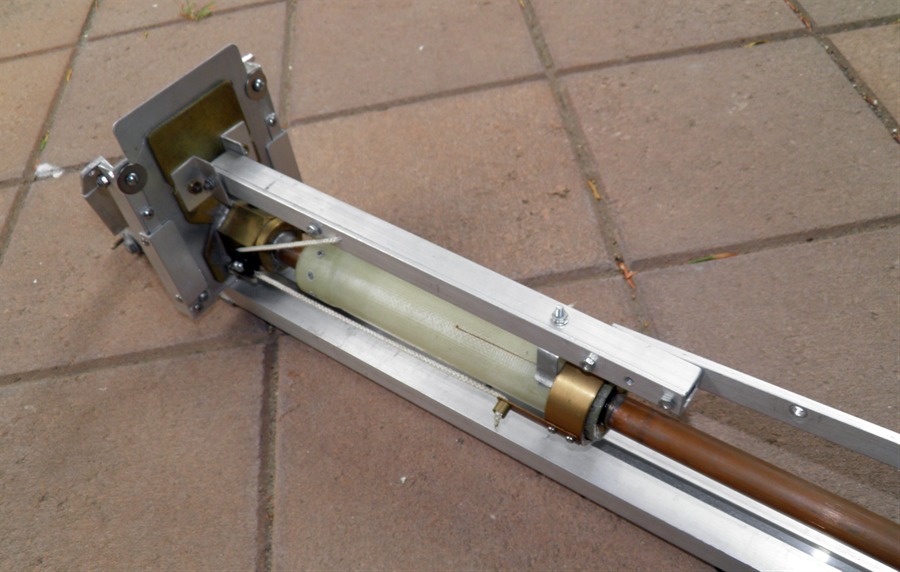
Extension arm on the release
lever.
Release heads are now easy to
swap
Release head slides in and is
secured with a pair of screws.
Small rocket stand-in template
to
get the correct spacing for the
release head.
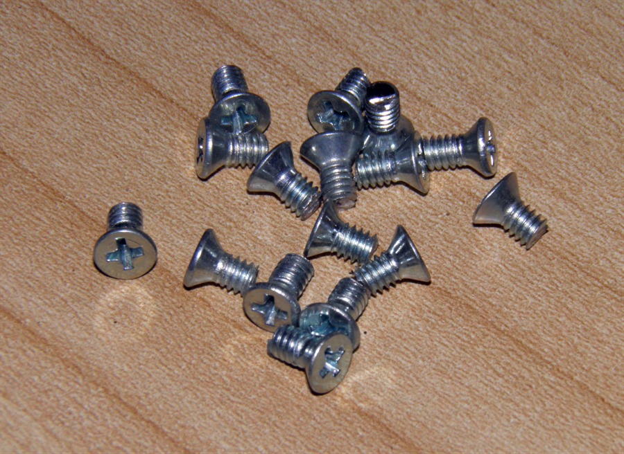
9th January 2013
- I reattached the video camera to the
payload section. We also shortened about 16
screws that attach the payload bay and
ejection mechanism, (because I misplaced the
box with the originals). A Dremmel tool with
a cut-off disk works a treat to get through
them cleanly and quickly. :)
Re-attached camera. The whitened
buttons
makes them more visible inside
the rocket.
Shortened screws
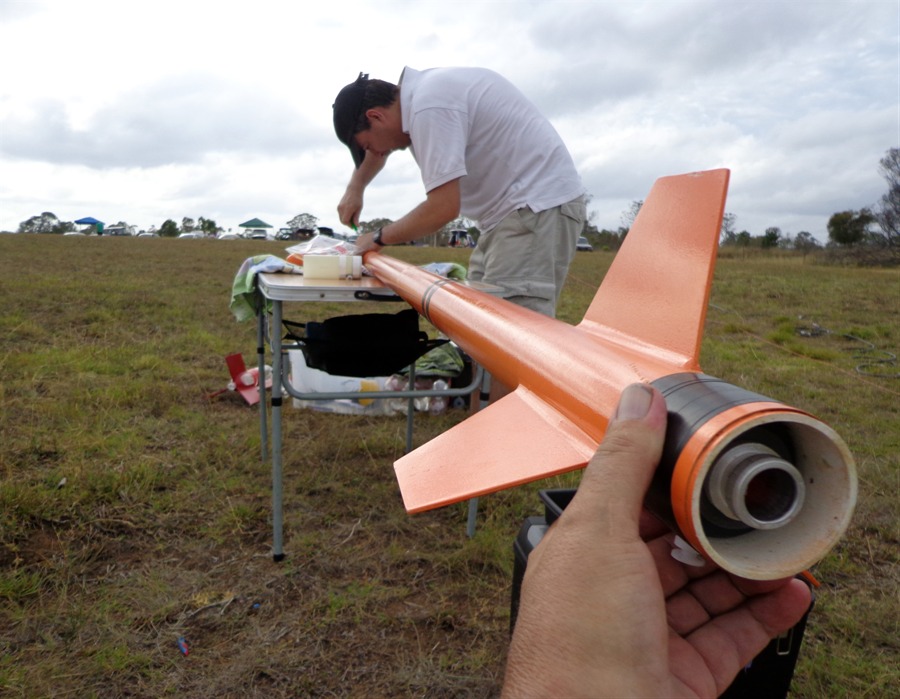
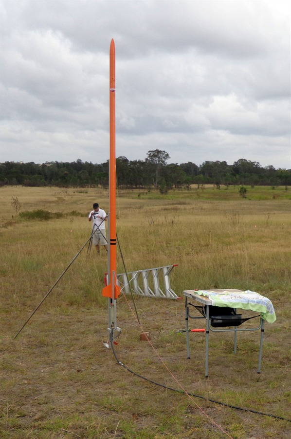
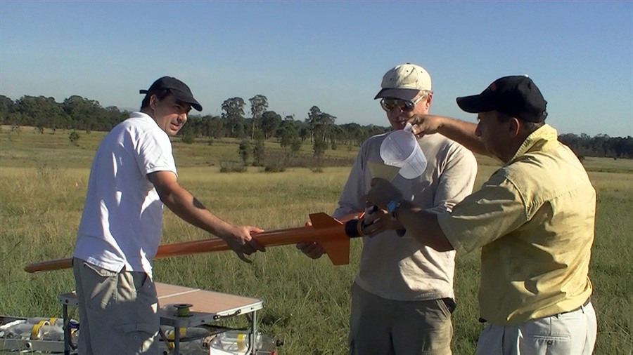
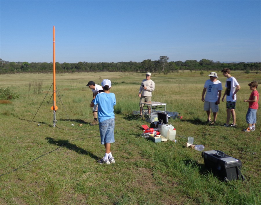
26th January
2013 - Launch day. Shadow II flies to
1248 feet (380m). See the full
flight report from day
129 for more details.
Prepping the rocket
Set up and ready to go
Fast launch
420psi
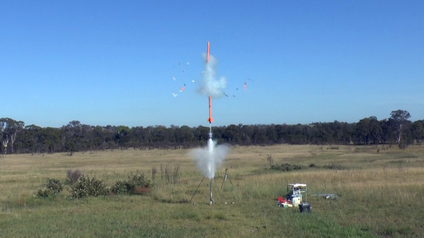
10th February
2013 - Shadow II CATOs. For full flight
report including failure analysis please see
Day130 Flight Report.
Filling with 1.7L of water
Almost ready to go
Pressurised to 440psi - BOOM
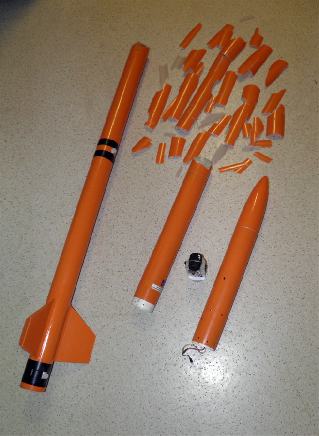
Fiberglass confetti
21st April 2013
- We trimmed the lower and upper sections of
the rocket and removed the two couplers. we
also had to remove a lot of dirt from inside
the rocket from where it landed.
23rd April 2013
- We bought a new roll of 84 gsm glass cloth
so we could repair the rocket body. 15m x
550mm wide cost $53
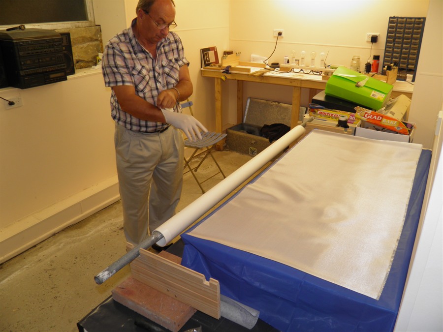
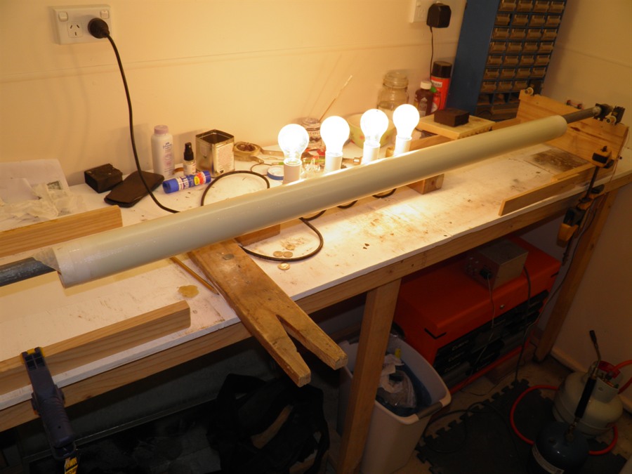
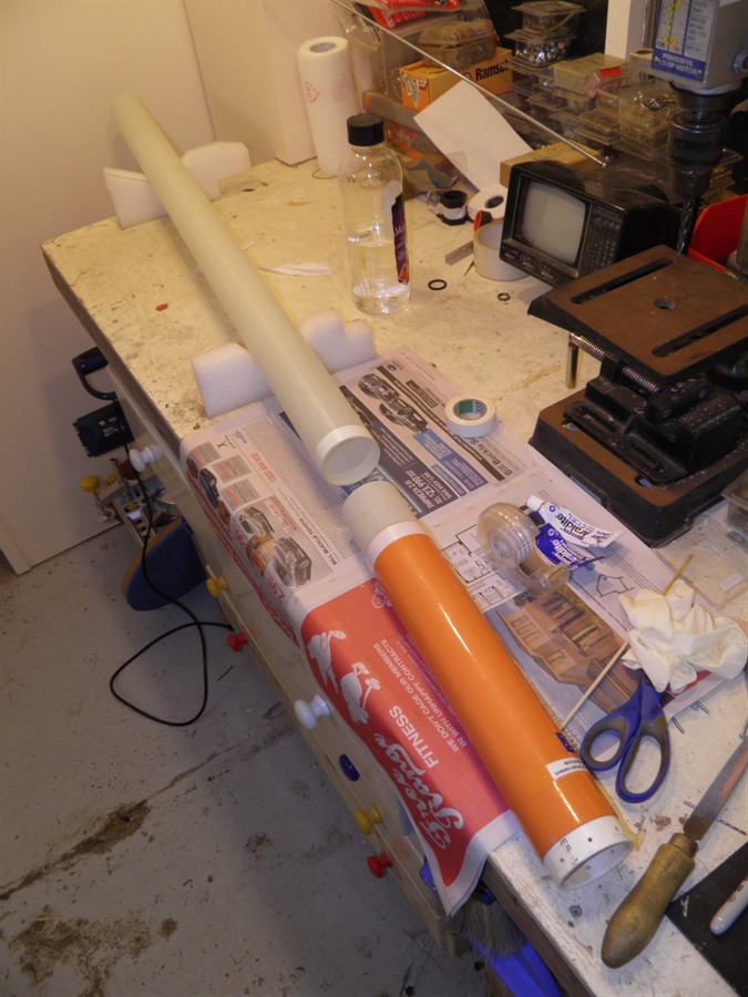
30th April 2013
- Today we rolled the new tube to
replace the broken section. We used 6 pumps
of the epoxy again which was just right.
Back on the rotisserie it went to cure.
4th May 2013
- Rolled a new coupler today from 200gsm
cloth. The cloth was 120cm long and about
16cm wide. One pump of the epoxy was enough
for the entire roll. We also pulled the
pressure chamber off the mandrel and again it
came off cleanly.
5th May 2013
- We rolled the second coupler today. We can
only roll one coupler at a time because we
only have the one small diameter mandrel.
7th May 2013
- Trimmed the couplers and sanded them down
to fit snugly into the tubes. We had to do
quite a bit of sanding as the couplers
turned out a little thicker than expected.
This may have been caused by using a brush
instead of a roller so the layers didn't
compact quite as much.
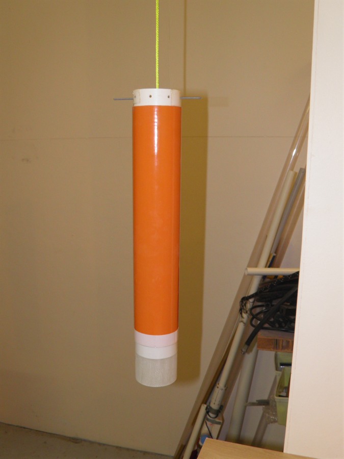
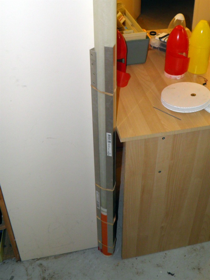
12th May 2013
- Glued the couplers into the forward
bulkhead section and the fin section. These
were suspended vertically to allow the glue
to flow back under gravity over the internal
joint. We again used the super strength 2
part epoxy.
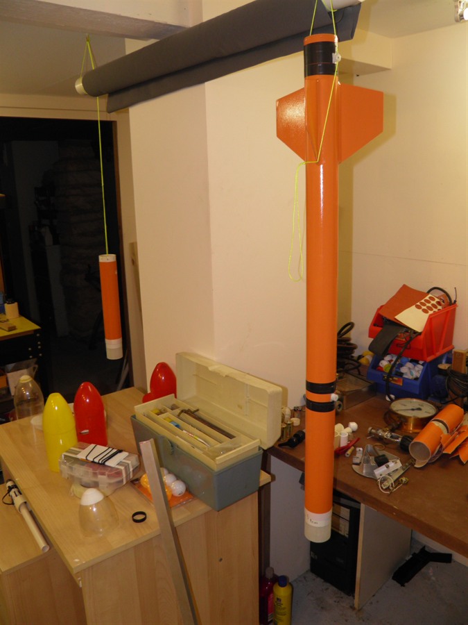
13th May 2013
- Glued the forward bulkhead section to the
new tube. We used 3 angle brackets attached
with rubber bands to keep the sections
aligned. We stood it upright to let the glue
flow back over the joint.
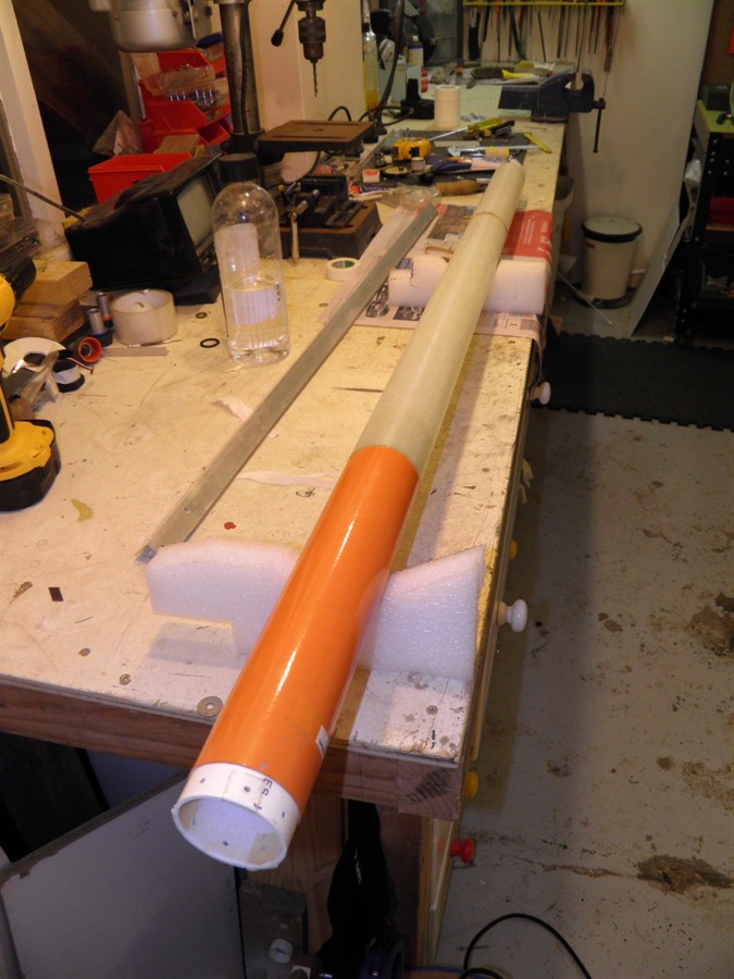
14th May 2013
- Glued the top section of the rocket to the
fin section. We again attached the angle
brackets to keep things aligned and stood it
on its end.
15th May 2013
- Spray painted the rocket body with putty.
This helps fill in some of the gaps and also
gives the paint a good surface to adhere to.
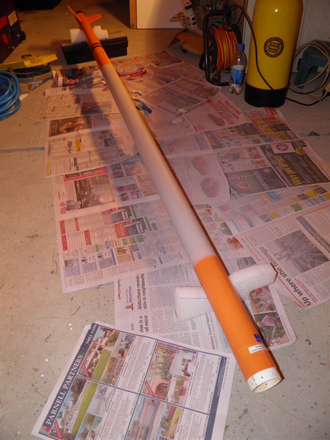
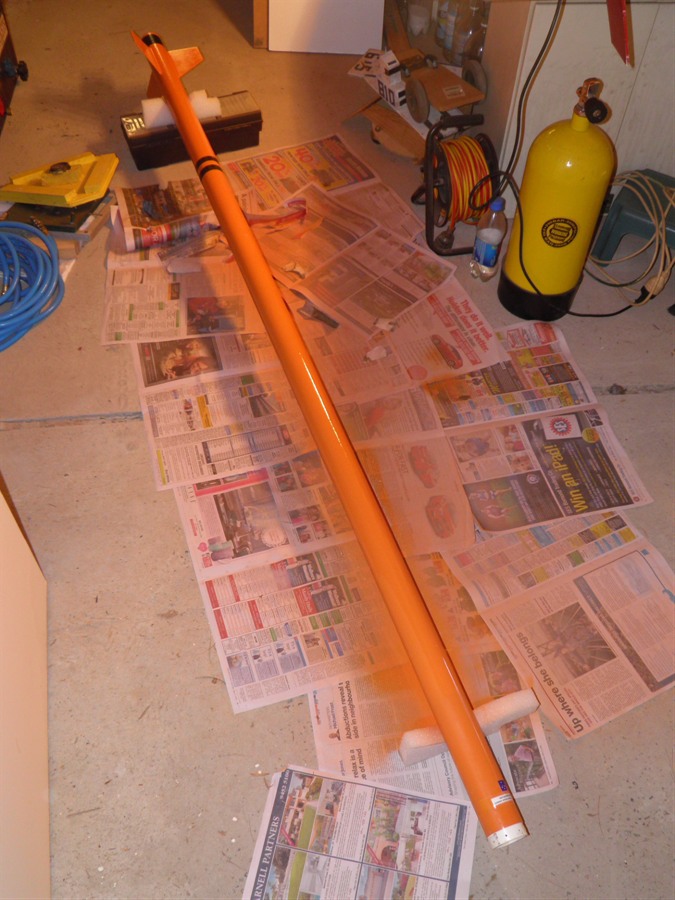
16th May 2013
- Sanded the putty with 400 grit sandpaper
and then finished with 1000 grit sandpaper.
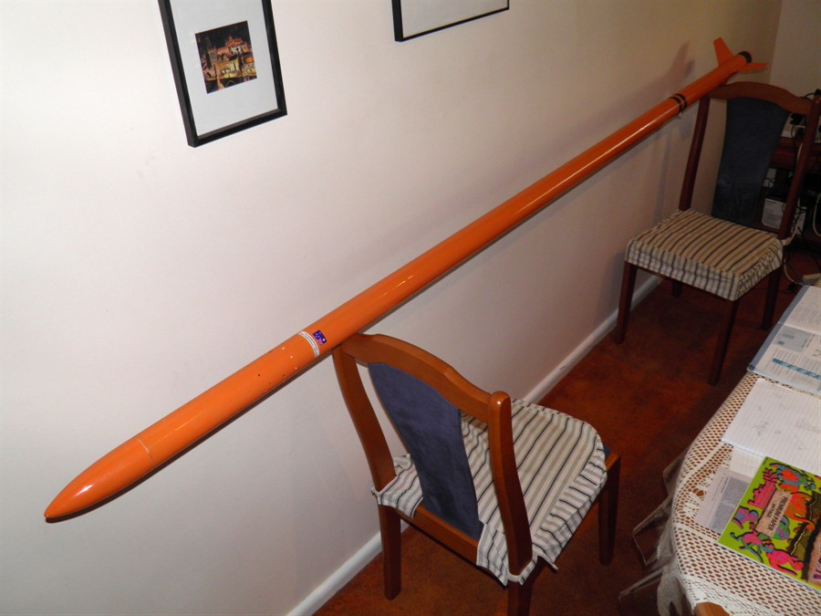
We then spray painted the rocket with the
bright orange paint. We applied about 4
coats and left it to dry.
19th December tested
shadow II standing up to 350psi
Feb 25 - S2 attach camera
- S2 attach altimeter with plastic pocket -
altimeterone - find S2 screws