This is the build log of our next rocket
project called "The Shadow". This water
rocket doesn't use PET bottles or FTC tubes
as the basis for a pressure chamber. Many of
the construction techniques are borrowed
from the model rocketry world. Rather than
scattering the development details of this
rocket all over the flight log updates, we
have decided to keep a dedicated page for
this rocket's development. The flights of
this rocket will still be in the regular
flight log updates along with our regular
development.
We will try to keep this log updated more
frequently to reflect the current status of
the build. You can click on the images to
get a more detailed view.
The log is in chronological order so to
see the most recent post you need to Jump To The Bottom. You may need to refresh this
page to see any latest updates.
CAUTION: If you are going to
attempt to build rockets such as these,
please exercise extreme care when testing
and flying them. This rocket uses high
pressures that can potentially cause severe
injury to yourself and those around you.
Always double check your equipment and
review safety procedures before every test
and flight. See more information on
Safety Guidelines.
Build Log
13 July 2011 - Started serious
design. After searching on and off for a few
weeks for sources of lightweight tubing, we
finally decided to make our own as we could
directly control the properties. There is a
good description on the Australian rocketry
forum
http://ausrocketry.com/forum/viewtopic.php?f=11&t=1966 describing the
process so we thought we would give it a go.
Sealing the end of the tube will need to be
worked out. Either a floating end cap and
nozzle with o-rings and screwed down or
permanently
glued into position.
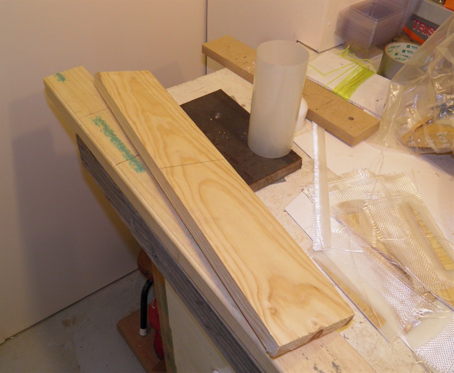
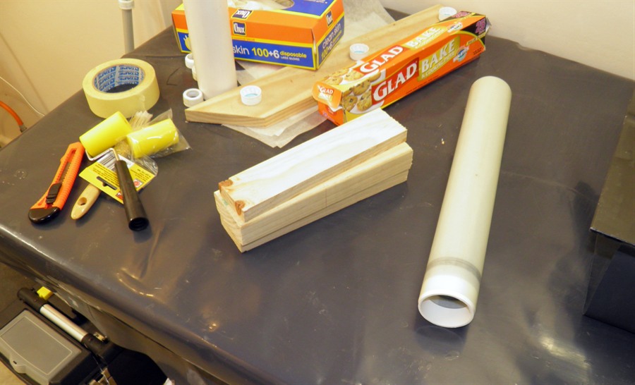
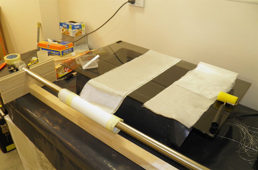
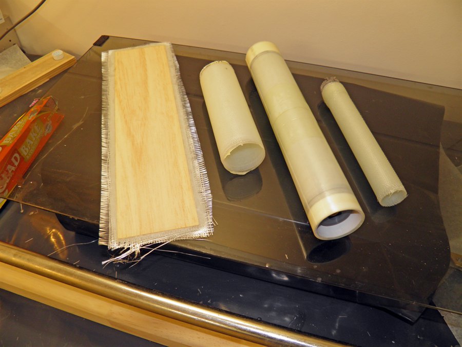
14 July 2011 - We found a 60mm section of PVC
pipe
about 30cm long under the house. We sanded it with 1000 grit sand paper and
removed any scratches and bumps. We then
applied a couple of coats of mold release,
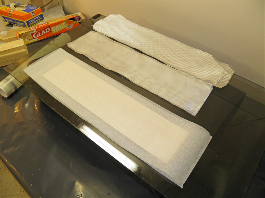
and polished it. We then cut a sheet of glad
bake baking paper in half and wrapped
it around the tube and attached the ends with masking tape. We wrapped 85gsm glass cloth
about 20cm wide over the tube 5
times and used West Systems as the epoxy.
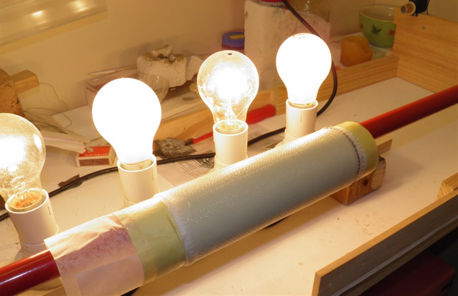
This was to test the whole manufacture process and
see how easily the tube could be removed from the PVC pipe.
We also wanted to see if we could make the
tube
non-porous without an internal bladder, and see what it's general strength
would be. We set the tube on the rotisserie
to cure.
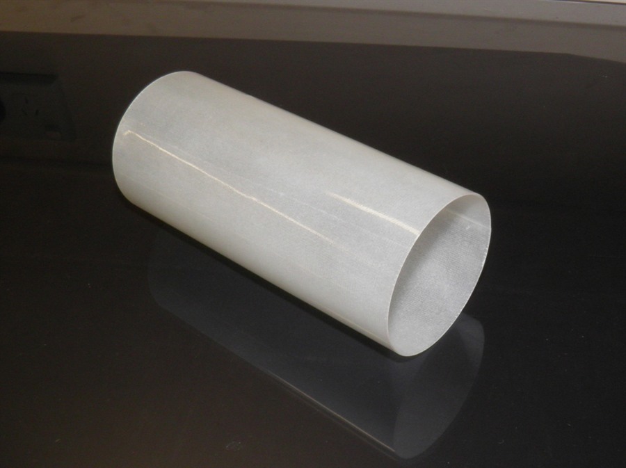
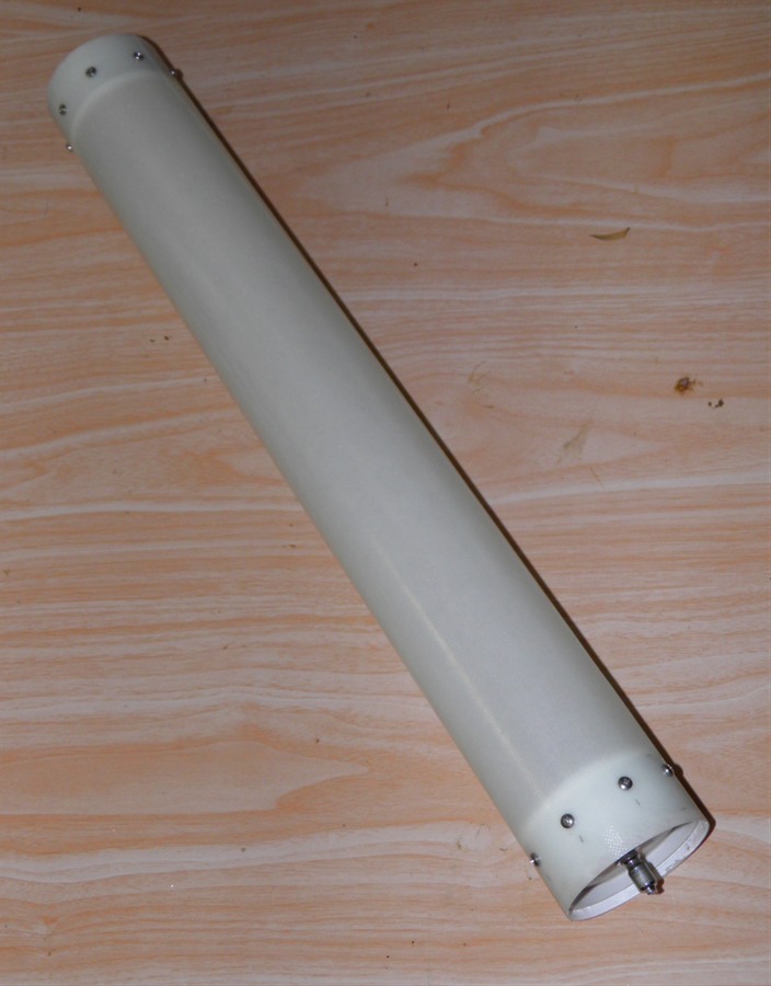
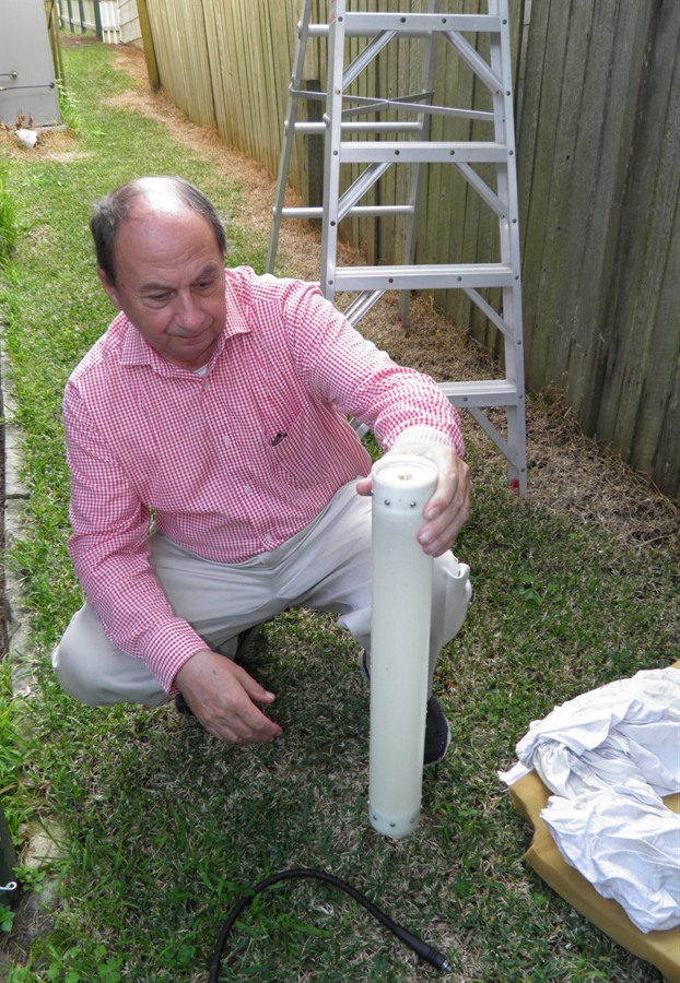
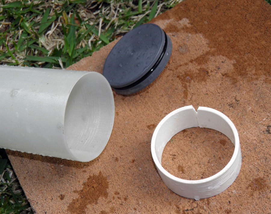
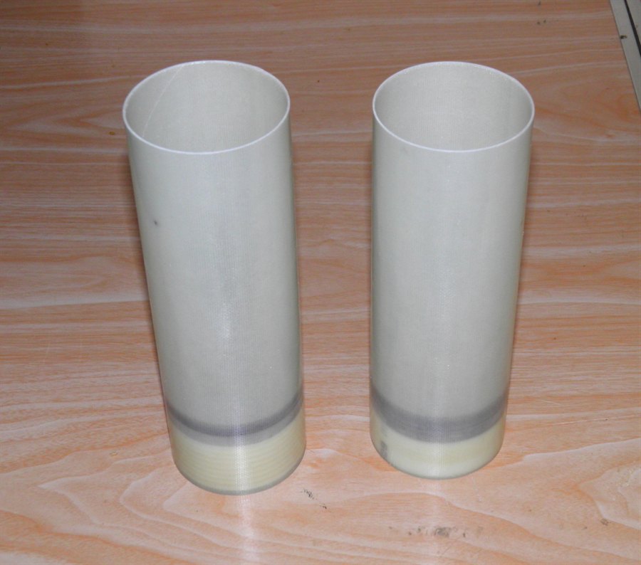
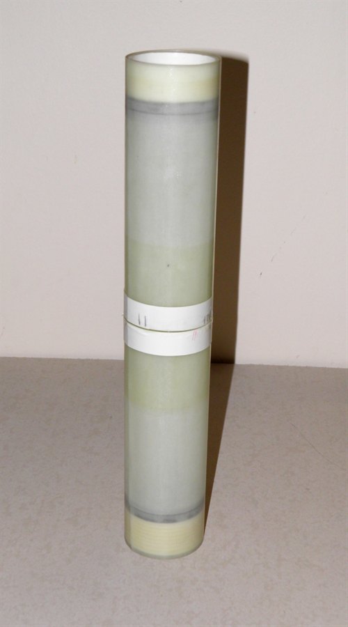
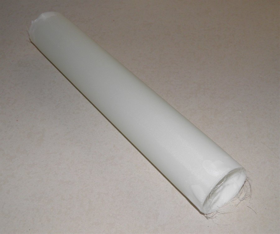
15 July 2011 - We removed the test tube from
the PVC pipe the next day. It came off very easily.
The surface finish looks
good and it also looks like it may be non porous,
but won't know until it's tested. We bought
60mm PVC end caps and 1m x 60mm PVC pipe
at the local hardware store.
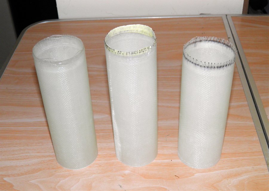
First tube - with ends trimmed
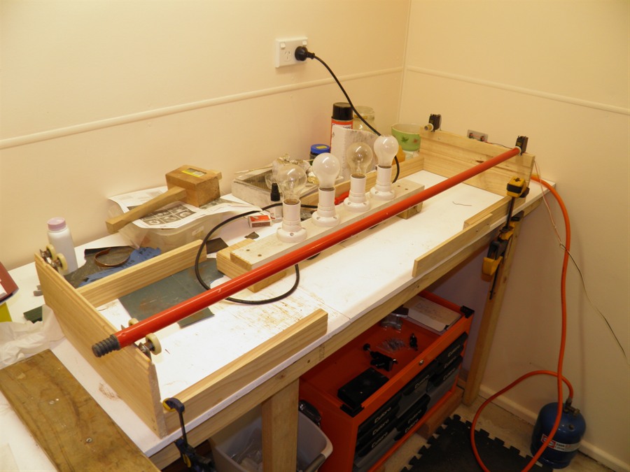
16 July 2011 - We sanded the PVC pipe with 1000
grit sand paper, applied a coat of mold release and
polished the pipe. We also made a new stand to hold
the
tube for rolling it. We also bought
foam roller brushes from the local hardware
store as doing long tubes was going to be
too slow with a brush.
New 1m PVC mandrel with extended
stand.
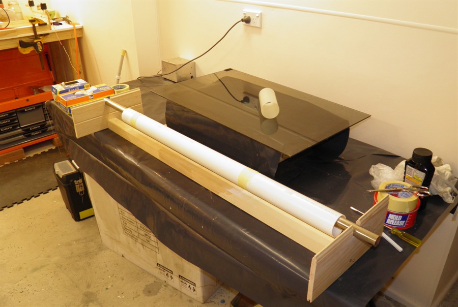
17 July 2011 -
We extended the rotisserie to fit the new
long PVC pipe and made a new axel to hold
the PVC mandrel. We then laminated the
first test sample to be pressure tested.
This one was more than double the length of
the first one. It uses 2 wraps of 85gsm
followed by 3 wraps of 200gsm and finished
with almost 3 wraps of 85gsm. This
combination used up 3 pumps of epoxy. The
roller made for quick and even spread of the
epoxy although it looks like there are more
surface bubbles. The epoxy was just poured
on from the mixing container. The Glad bake
paper was cut in half lengthways and spiral
wound this time with about 2cm overlap and
secured with masking tape to the pipe so it
would not unravel.
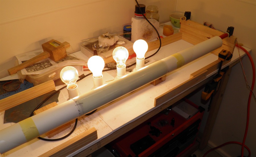
Extended rotisserie
Letting the second tube cure
near some heat lamps.
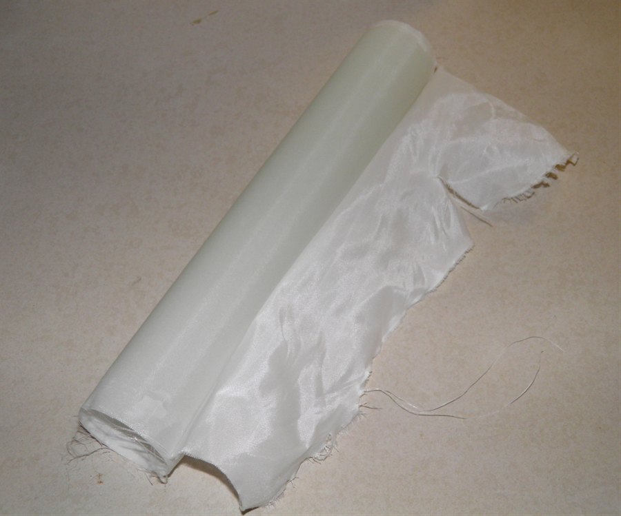
18 July 2011
- We removed the test sample from the PVC
pipe. It just came off without any effort at
all, I expect doing a full length tube
should not be an issue. The sample looks
very good and very strong. The surface
bubbles seen during curing were almost all
gone.
Weight of sample is 122 grams for 345mm
with an average wall thickness of 1.1mm. We trimmed
the end sections of the sample with a
hacksaw.
I spent some time Investigating the
differences between s-glass and e-glass -
S-glass is apparently up to 30% stronger and
15% stiffer than e-glass. Cool, though I
don't have the cost differences yet.
Second tube as it came off the
mandrel.
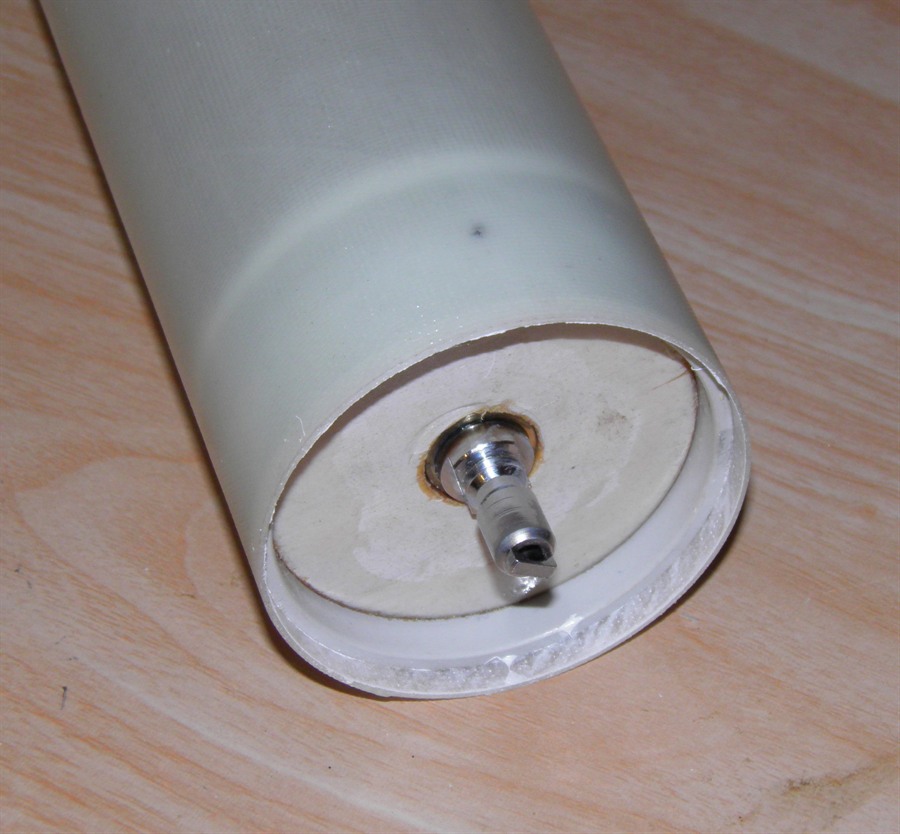
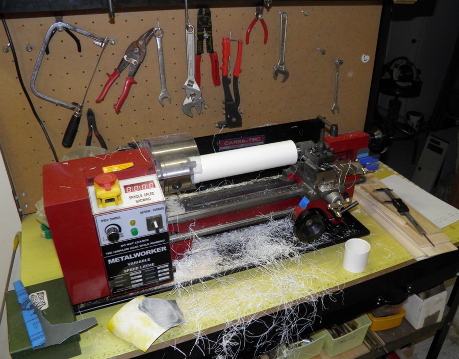
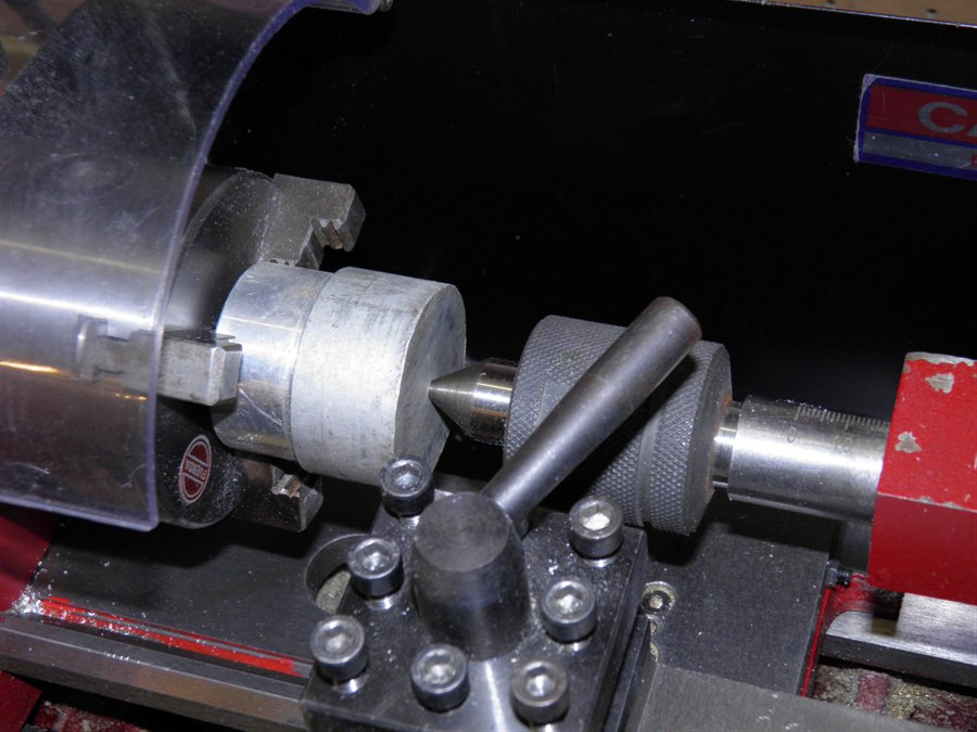
19 July 2011 - We machined down an end cap to fit
inside the tube. It's a little distorted because
of how the lathe chuck grips it. We need to
find a better way of doing this.
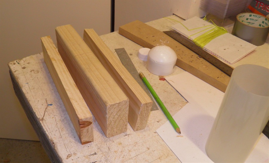
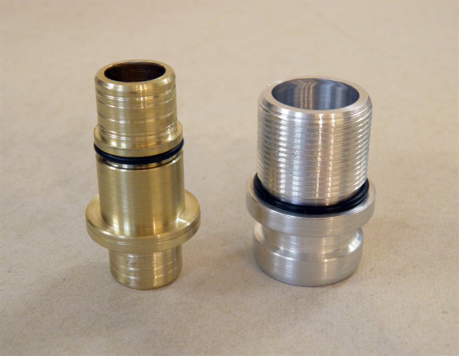
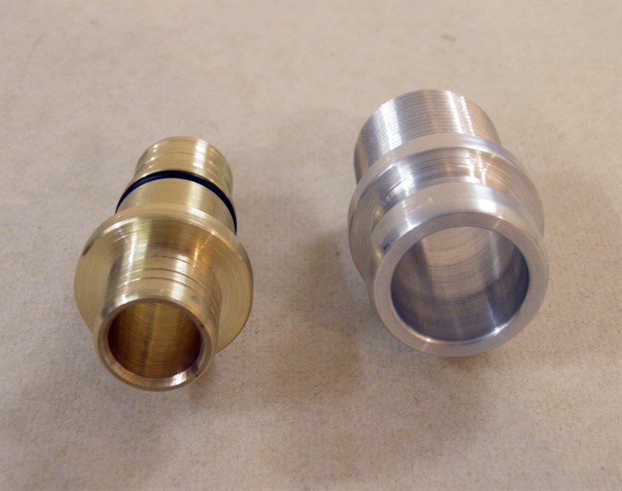
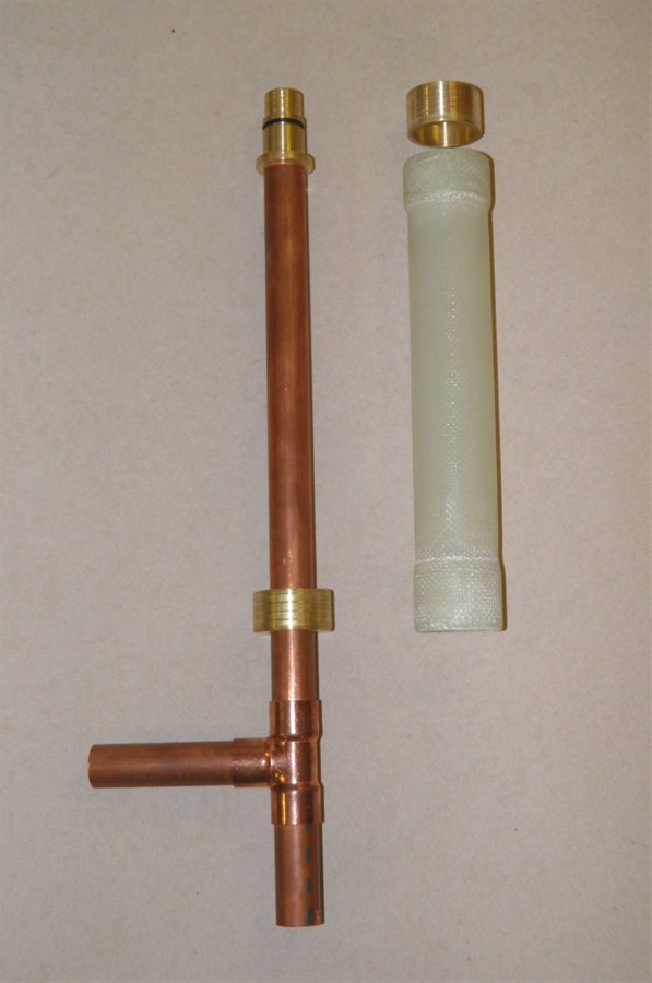
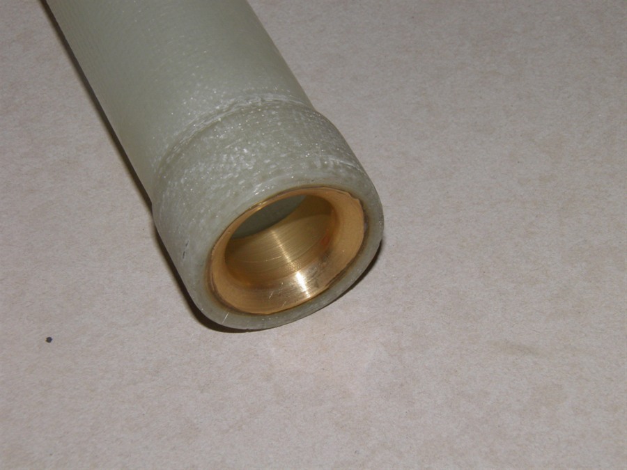
23 July 2011 -We machined down another two end
caps. We also machined two wooden blocks to be used
for reinforcing the end caps. We used one of
these blocks wedged inside the end cap to
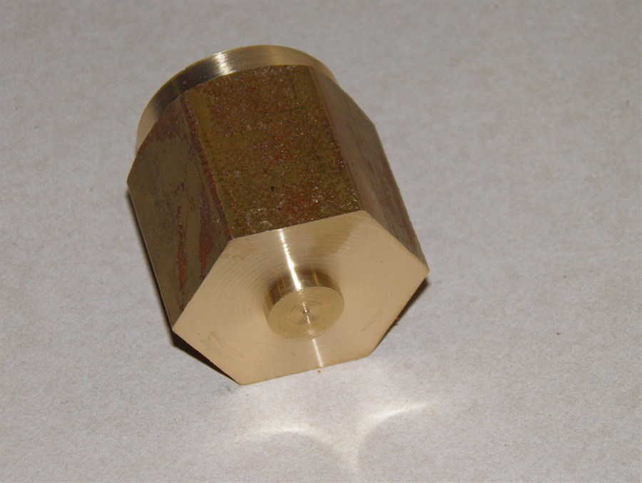
get a good grip without distortion. Dad also machined a
brass
hose adapter to fit into the end cap for
pressure testing.
Components for pressure testing
the tube.
Hose adapter for pressure
testing the tube
The hose adapter fits on the
inside
Reverse view of the adaptor.
Wooden blocks are fitted inside
the
end caps to reinforce them.
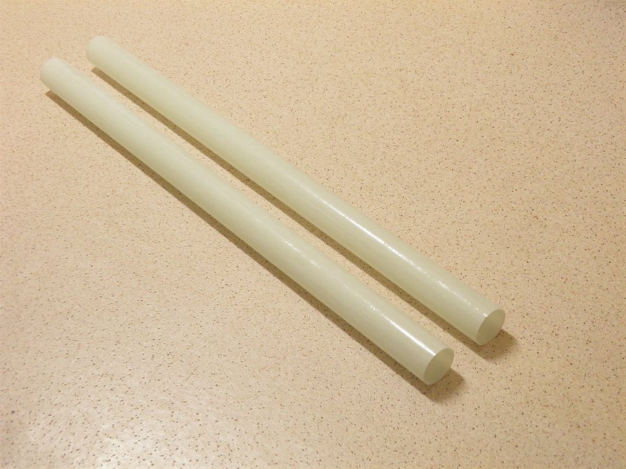
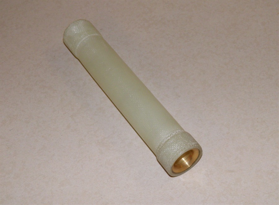
3 August 2011 -
We made up a new fiberglass tube 50cm long.
136 grams. This one used the 85gsm cloth
only with 2 x 800mm long sections. The
standard cloth width was just cut in two.
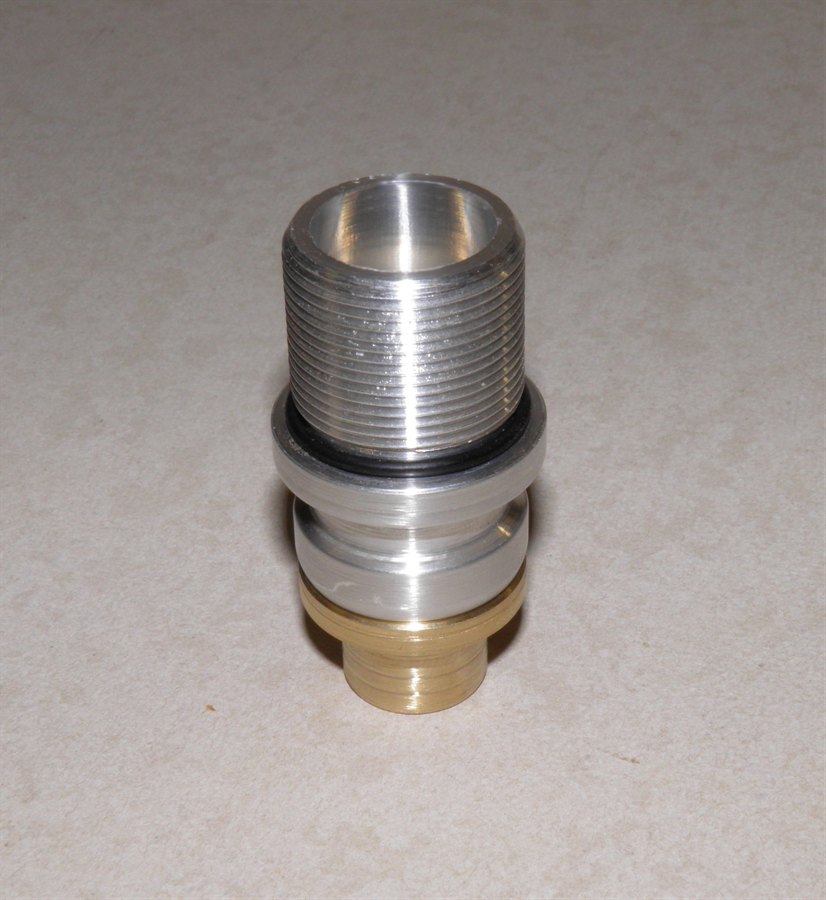
We also glued the wooden
reinforcements into the ends of the caps, and
glued in the hose adaptor.
The hose adaptor is glued into
the cap with
epoxy to seal it.
The wooden blocks are also glued
in place
with the epoxy
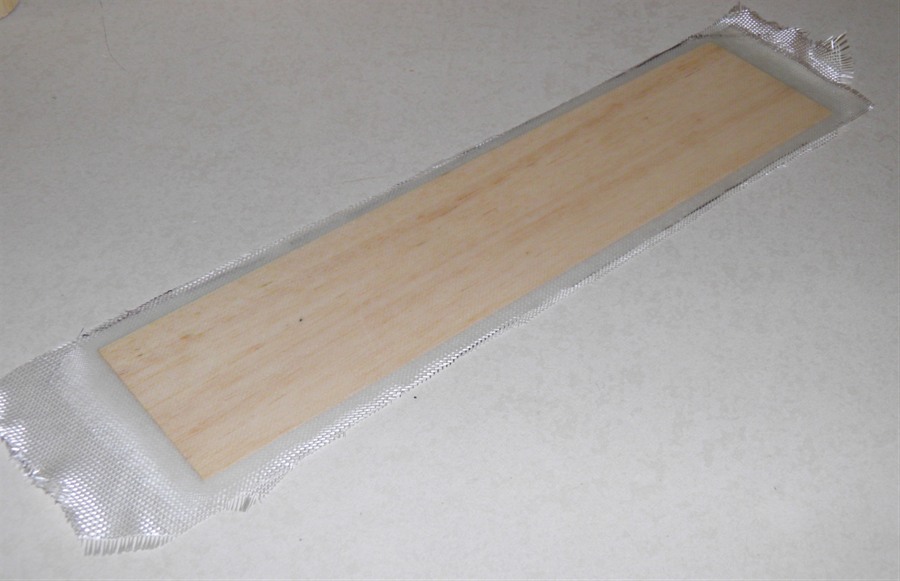
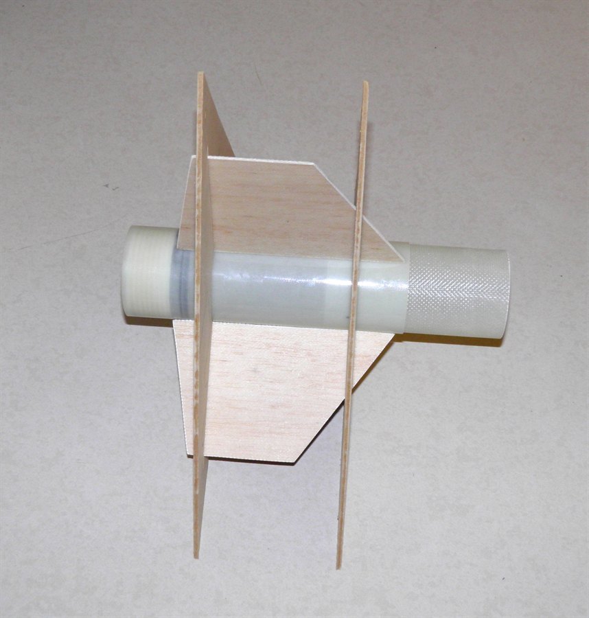
We made up two fin
prototypes. One used a 1mm balsa core with a
first layer of 200gsm cloth with another
layer of 85gsm cloth on top. This was done
to both sides. A second fin was made with a
2mm balsa core with the same 200gsm and
85gsm sandwich.. This was then placed
between two sheets of baking paper and onto
a sheet of glass with a flat board on top.
The whole thing was then weighed down with a
couple of bricks. The 1mm balsa sheet had a
slight bend in it when putting together.
Fin fiberglass/balsa sandwiches
ready to be cut out.
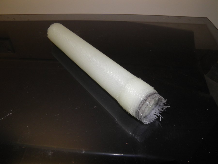
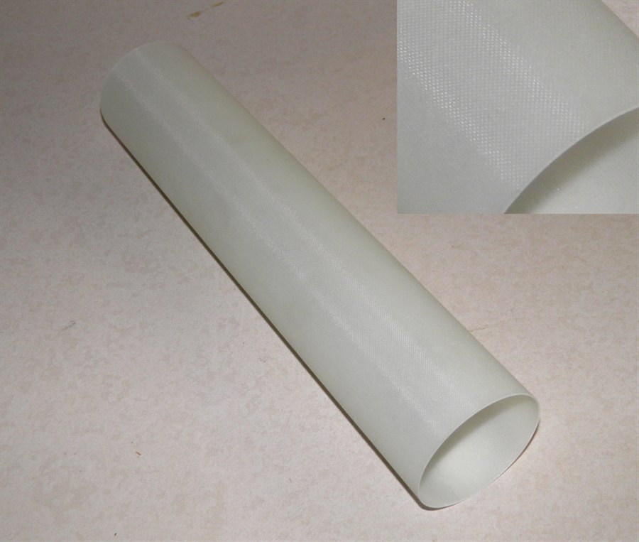
4 August 2011 -
Removed the tube off the mandrel and again
it was very easy to pull off. Full length
tubes should not be an issue. To remove the
baking paper from inside the tube is easily
done by inserting a broomstick and turning
it to unwind the paper from the inside wall
of the tube. The tube was trimmed and the
475mm length weighed 132 grams. This would
make a 2m tube weigh 555 grams + coupling
weight.
The new tube just after being
pulled off the mandrel.
The fin prototypes
looked reasonable and both were nice and
flat with a good surface finish. After
cutting them out, both the 1mm and 2mm balsa
versions weighed in at 25 grams. While they
were quite stiff when trying to bend along
the fibers, they were relatively easy to
twist which would unlikely to be suitable
for high speed. The fin thicknesses were
2.5mm
and 3.4mm. One way to stop the twisting may
be to rotate one of the glass layers 45
degrees. Though it still looks like we may
need to go with 1mm carbon fiber fins
because of it's stiffness and weight.
Test fins made from two
different thicknesses of balsa.
17 August 2011 - Today
we glued in the end caps with Sikaflex 11FC
into the long tube. The idea is that the
Sikaflex will seal the join rather than
necessarily hold it together. The bulk of
the strength will come from a set of screws
that will hold the end caps in. The one
concern we have with just using epoxy to
seal the end caps is that as the tube
pressurises it will swell and try to lift
away from the edges of the cap breaking the
seal. We may also consider just gluing with
epoxy a small ring of fiberglass behind the
end cap to the inside wall of the tube,
perhaps even 5mm wide. This would be far
easier and lighter and have less drag than
the screws.
End cap glued into the tube with
Sikaflex 11FC
Hose adapter end plug glued into
the
other end of the tube.
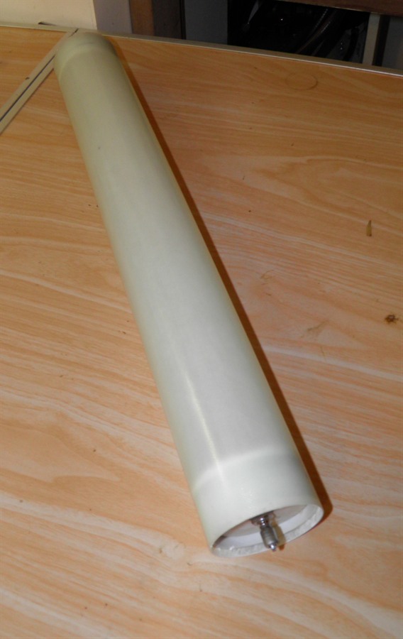
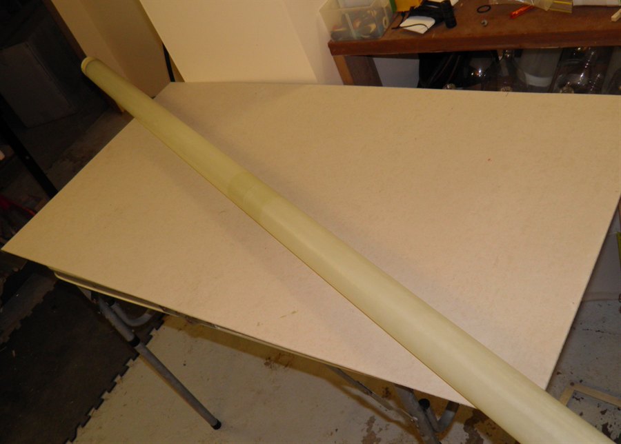
The whole tube
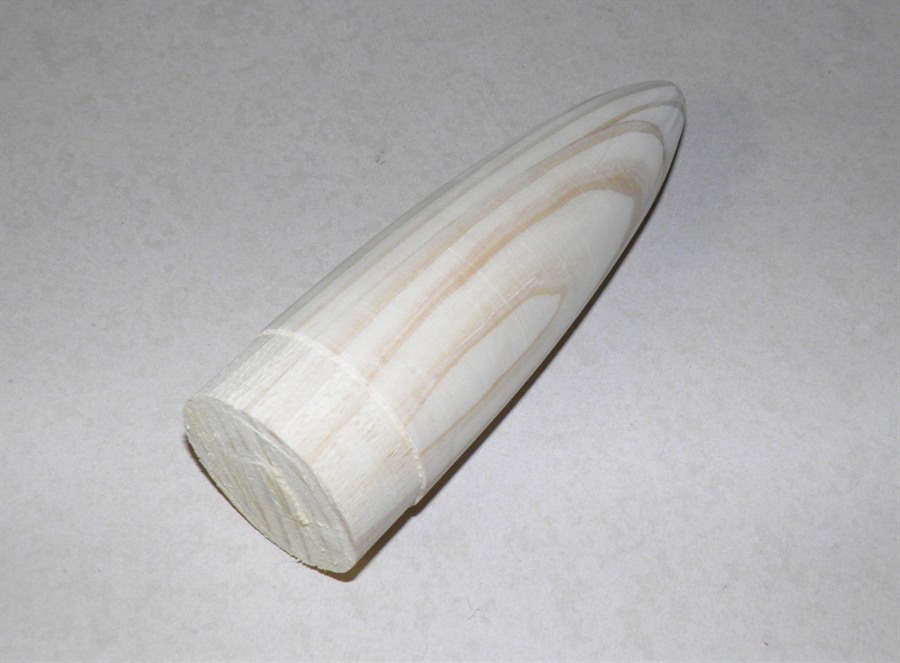
Some wood of cuts to be made
into the
nosecone plug
Cut to size and ready for
gluing.
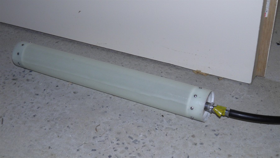
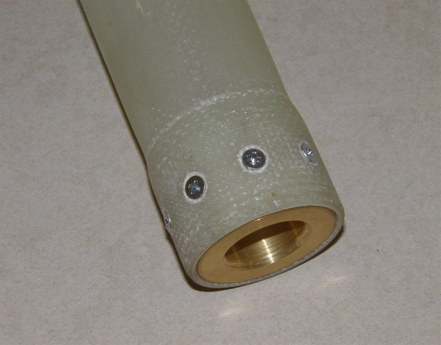
21 August 2011 - We drilled 8
evenly-spaced holes and tapped them at
either end of the test tube. We screwed the
end caps down with 3mm SS screws. The line
of screws is about 7mm back from the inner
edge of the end cap. We then screwed in the
quick release adaptor and pressure tested it
to 50psi to check for leaks. We only used
air for this test and will need to do a
hydro test when testing to higher pressures.
The tube was sealed well and we're glad that
the tube was non-porous which was an initial
concern we had when making our own tubes.
Drilling the holes for the
screws.
Drilled holes.
Tapping the holes for the screws
8 stainless steel screws
Tube ready for testing
Quick seal check at 50 psi.
27 August 2011 - Today we bought a
3m long 60mm PVC pipe from Bunnings to make
the longer mandrel so we can make tubes the
full width of the glass cloth. We also
bought a 1.5m long copper pipe that will
be used as a launch tube for the rocket.
This also determines the minimum nozzle
diameter. The copper tube was chosen so that
it can be soldered for mounting or
extending.
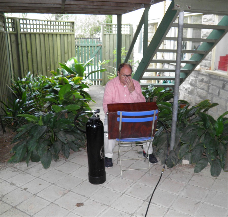
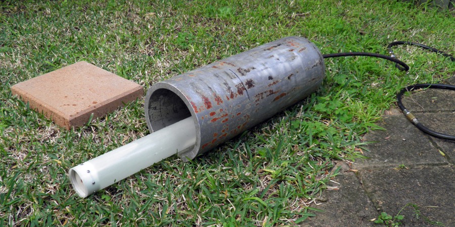
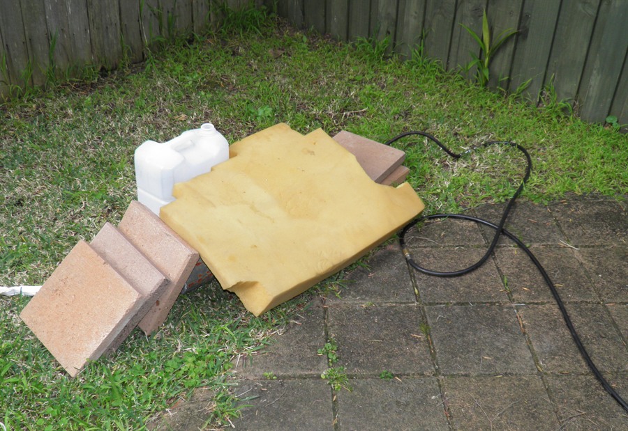
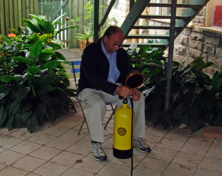
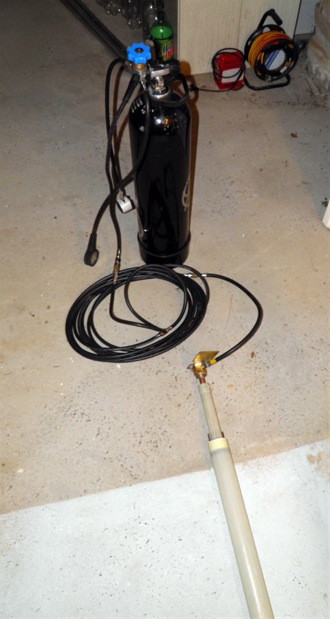
28 August 2011 -
Pressure testing time. Today we
hydrostatically tested the tube to see how
well the end caps would hold and how strong
the tube is. We placed the tube inside the
scuba tank again to protect against flying
debris. We used our high pressure panel to
get the tube up to 300psi as that is the
maximum it will go up to.
Setting up for a high pressure
test
The tube is completely filled
with water
Tube being placed inside the
scuba
tank to reduce noise and
potential debris.
The end is stuffed full of
rags and concrete pavers
pilled up
against it. Extra foam
placed over the to reduce
noise.
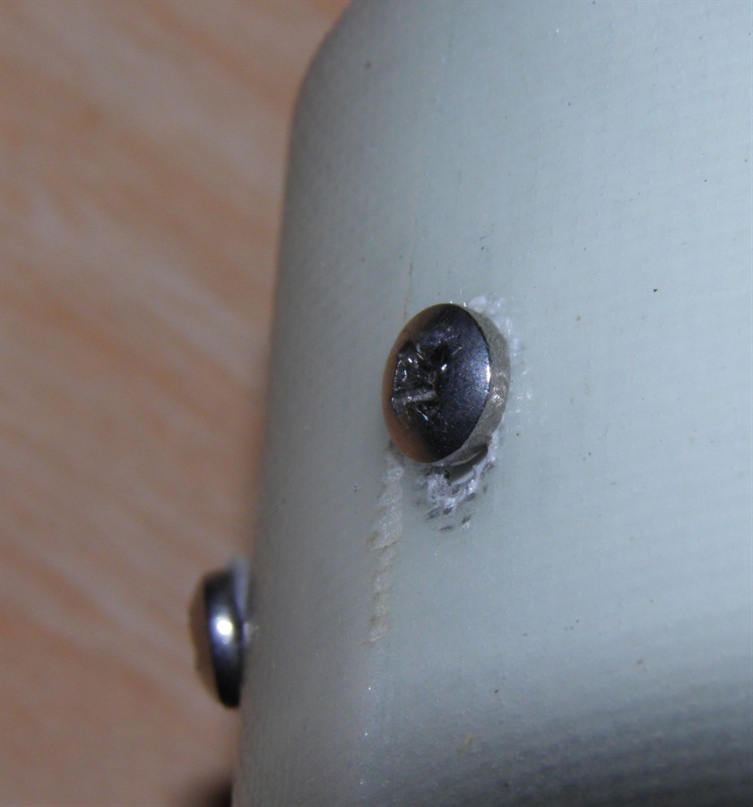
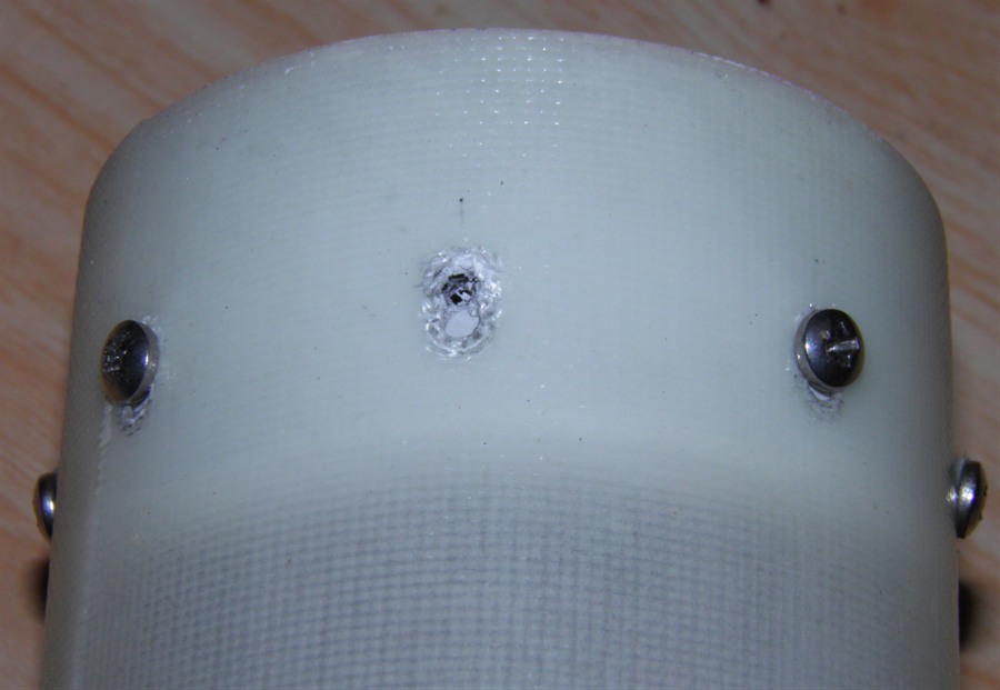
When we shut off the
air supply we could see that the line
pressure was slowly dropping which meant
there was a leak. We let the pressure drop
to around 100psi before looking into the
scuba tank. On inspection we could see the
tube was leaking from both ends. As more or
less expected the screws had ripped through
the fiberglass walls and allowed the cap to
move about 5mm at one end and about 2-3mm at
the other end. This movement broke the glue
seal and allowed the water to flow past the
cap. At 300psi there was about 600Kg pushing
on the end caps!
Showing how much the screw moved
under pressure
Screw removed. The amount of
movement was
about 5mm.
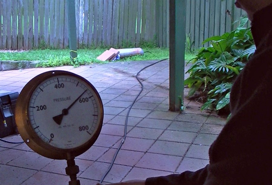
Although disappointing we learned one
way not to seal the end caps. We also know
that the tube held at least 300psi which is
a good result. Next time we will use our
direct HP tank adaptor with a gauge that
goes up to 800psi to measure the higher
pressures.
We're going to remove
the end caps and trim the tube and use it
again for the next test. We now have to
redesign how the end caps will be sealed.
Most likely we are going to machine them out
of plastic and use an o-ring to seal them.
We are also going to try gluing in the
fiberglass support ring to stop the end cap
from moving.
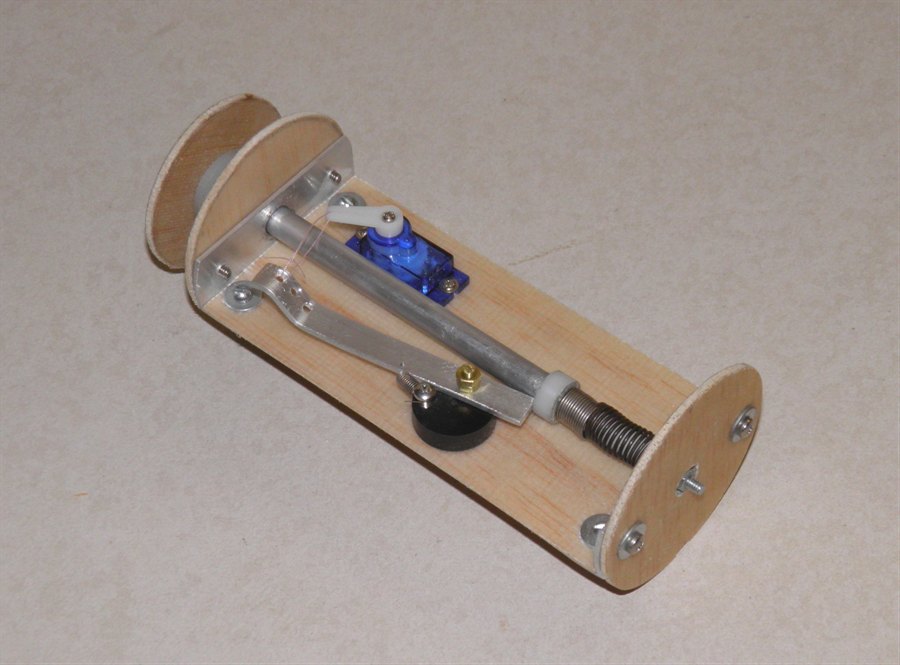
30 August 2011 - Today
we started designing the parachute
deployment mechanism. Due to expected speeds
and acceleration we are going with an inline
deployment mechanism as opposed to a side
deploy that we normally use. Having first
considered just using BP like normal rockets
do we decided to do a piston ejection method
like a lot of people use in FTC rockets.
Examples of piston
eject methods:
Robert Youens VDTT and Bernard
Willaert's remote controlled deployment
mechanism
#68.
The
main reason is that we can test it as much
as we need without the need to obtain BP. It
also results in cleaner system although it
is heavier.
4 September 2011 - Today
we machined down two pieces of PVC plastic
so that we can machine the end plugs out of
them. We had to attach an adaptor so that we
could grip it in the lathe's chuck. Because
the other end plug has the hose adaptor, we
could just drill a hole through it and hold
it with a bolt.
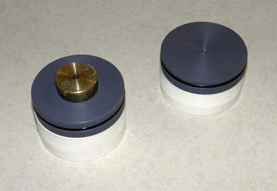
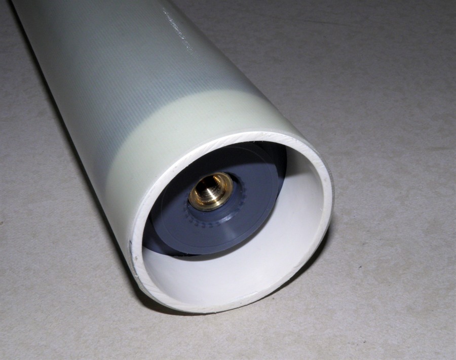
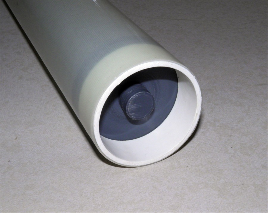
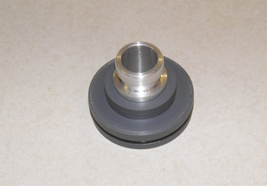
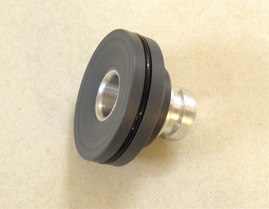
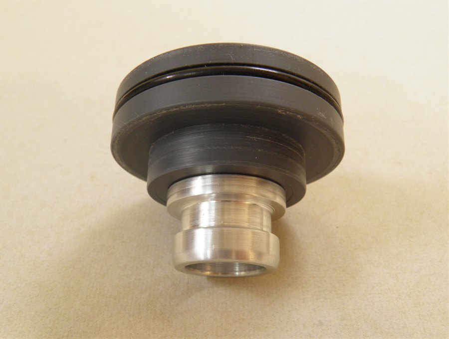
10 September 2011 - Today
dad machined down the two end plugs to
accurately fit inside the tubes. The hope is
that we will be able to re-use these ends on
the actual rocket as they are not being
glued into the tubes. The nozzle plug has
been made with a thread so that we can screw
in the hose adaptor that has had a matching
thread cut into it. We added an o-ring to
this so we didn't have to glue it in place
Once the testing is finished we will cut a
much bigger thread into this plug that will
be used to screw in the nozzle. The end
plugs are a little on the heavy side, but
not too bad. It should be possible to
lighten them in the future,
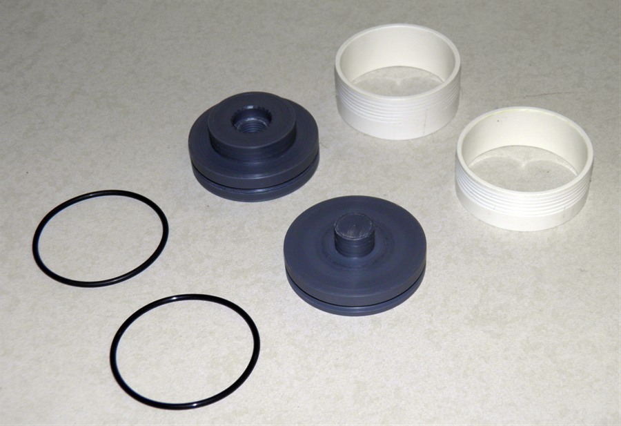
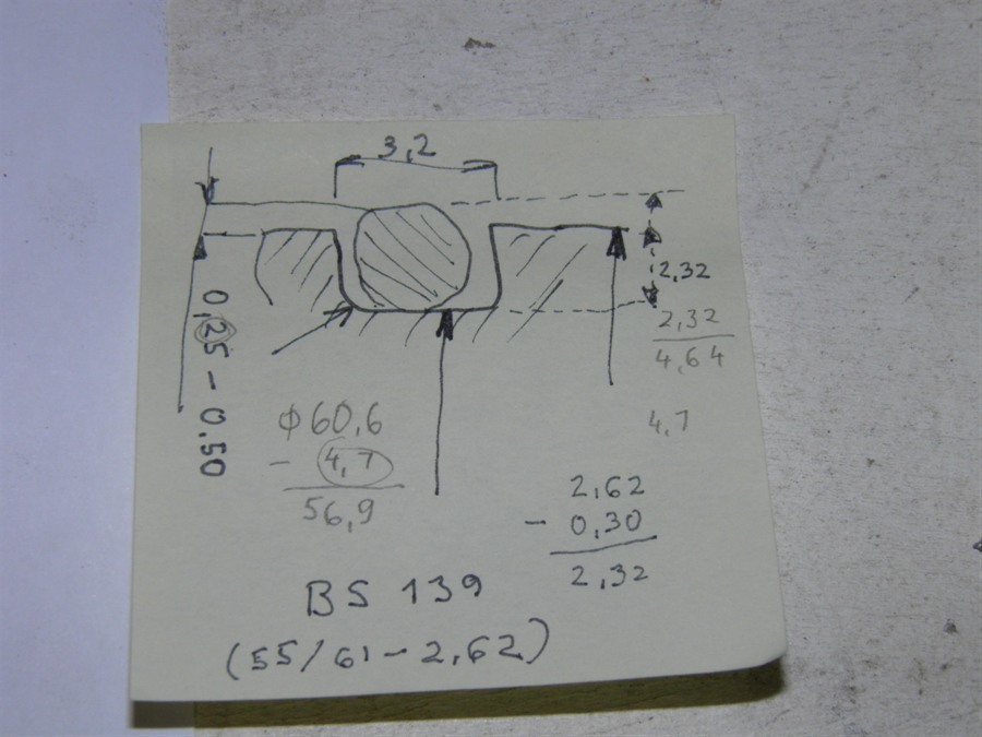
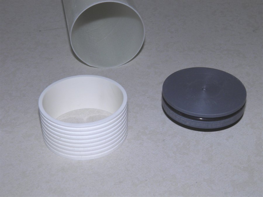
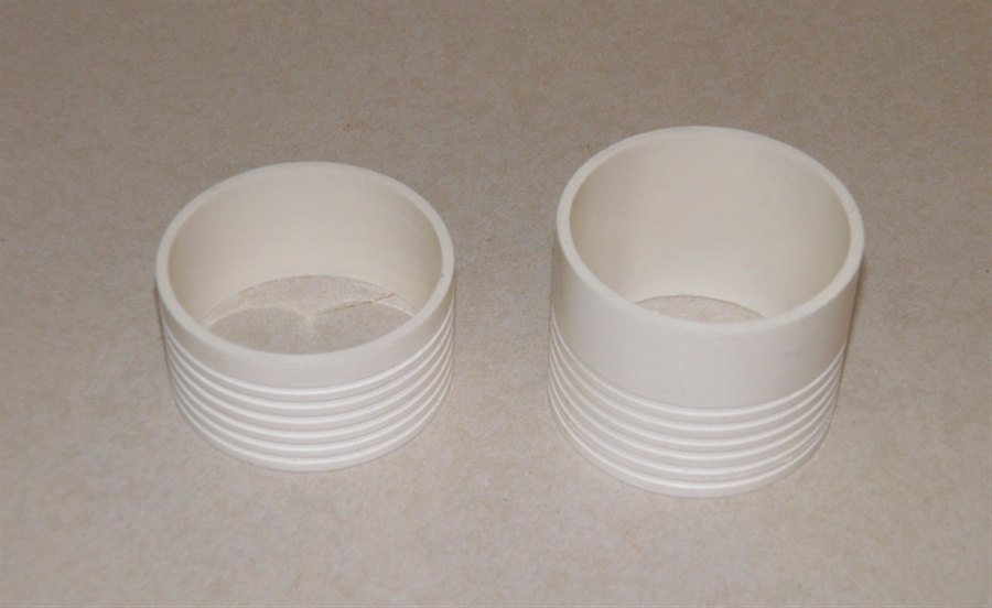
We also machined up a
couple of PVC rings that will be glued
behind the end plugs that will hold them in
place. Dad also bought the right o-rings
(BS-139) during the week so all that is left to do is
glue in the rings and we can do another
pressure test.
O-rings, plugs and support ring
The hose adaptor is now screwed
into the plug and sealed with
it's own o-ring.
Test fit inside the tube.
Test fitting the other end plug.
We also built the new
stand to allow us to make the longer tubes
that are the width of the fiberglass cloth.
O-ring groove diagram and
dimensions.
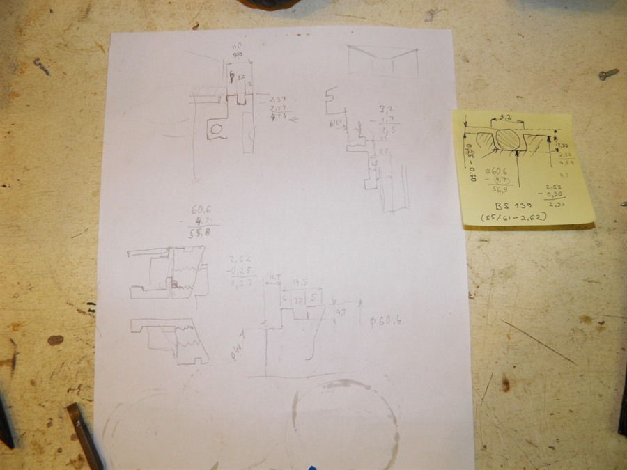
Designing the plugs.
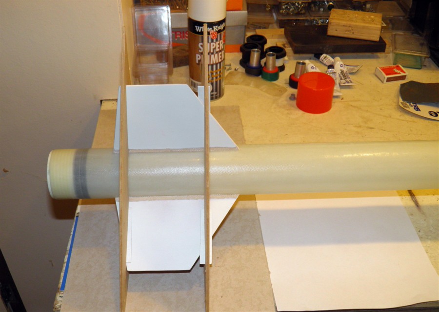
12 September 2011 - Today
we layed up a new balsa/fiberglass sandwich
to be used for the fin set. The 200gsm cloth
was bias cut to try to prevent the twist we
saw with the previous test. The 85gsm cloth
was just straight cut. Again the whole thing
was put on a sheet of glass and pressed
together with a board and pavers on top. We
also glued the three bits of wood together
that will be made into the nosecone plug.
Lastly we also glued in one of the end caps
in the tube to be pressure tested. It was
difficult to get the end cap back down after
the ring was inserted because we didn't
grease the o-ring. We didn't want to apply
grease anywhere inside the tube as this may
have an adverse effect when gluing the ring
in.
The deployment
mechanism components are also coming
together. We cut up the test fins we made
previously and are using the reinforced
balsa wood to make up the bulkheads,
Getting ready to make the balsa
sandwich.
Gluing the end plug as well as
the nosecone plug.
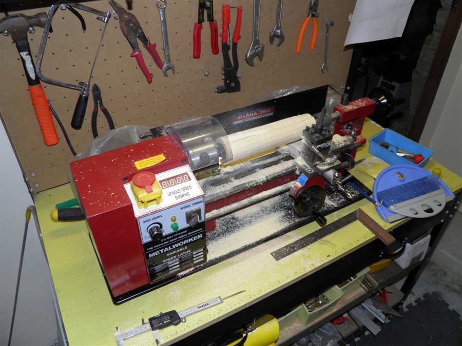
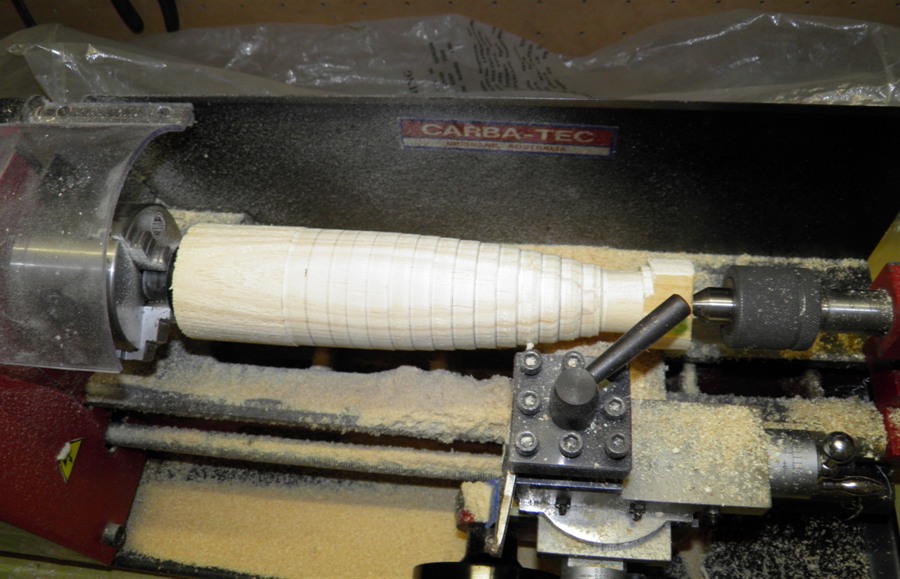
13 September 2011
- We started machining the nosecone plug
today. We turned it down to a cylinder of
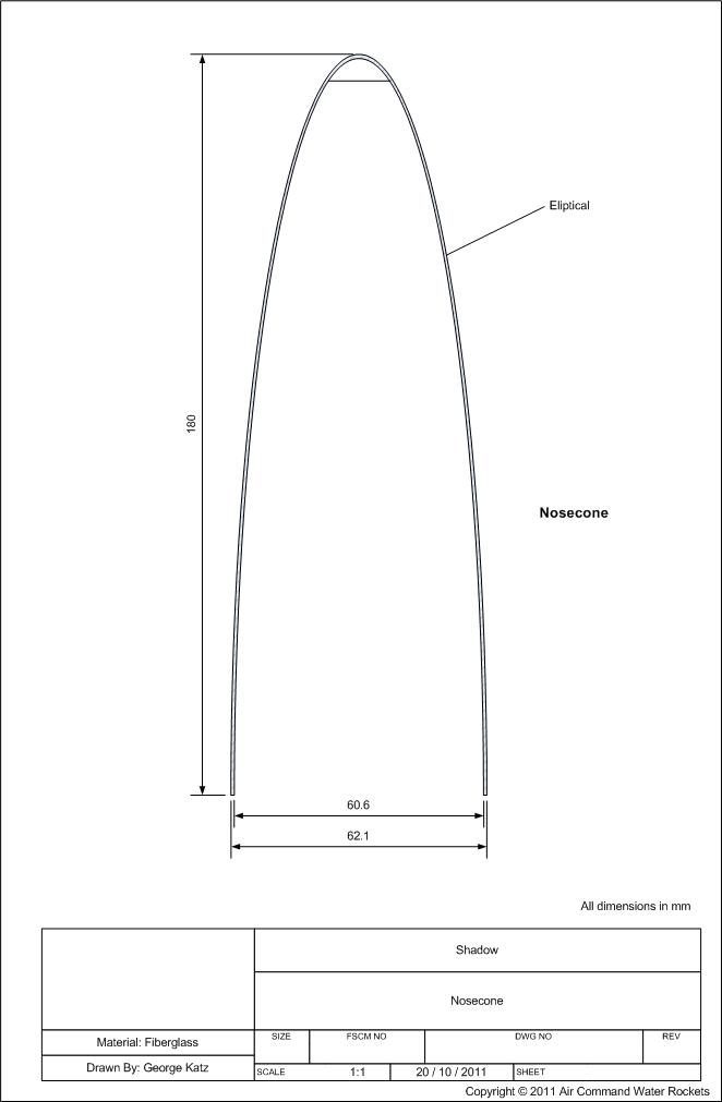
about 62mm. The correct elliptical nosecone
shape will now be cut into in the next day
or so.
Turning down the nosecone plug
block of wood into a cylinder.
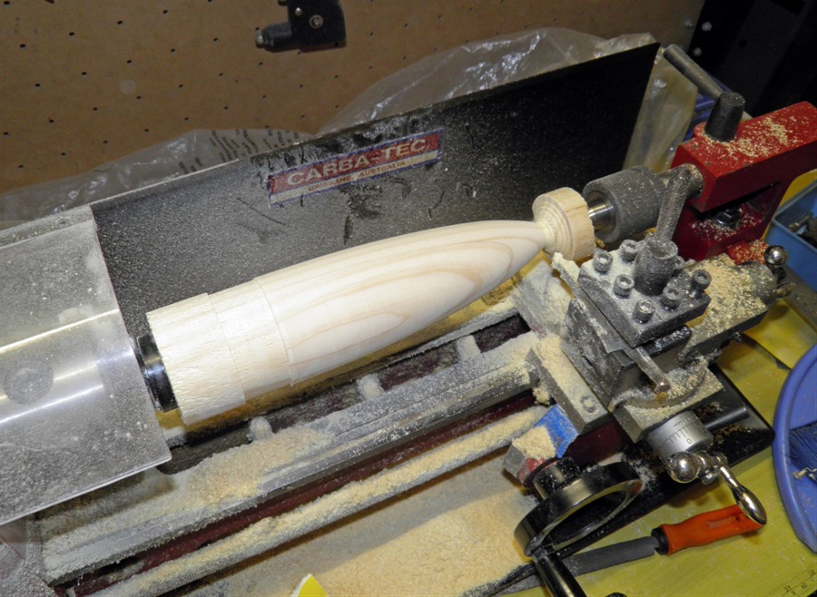
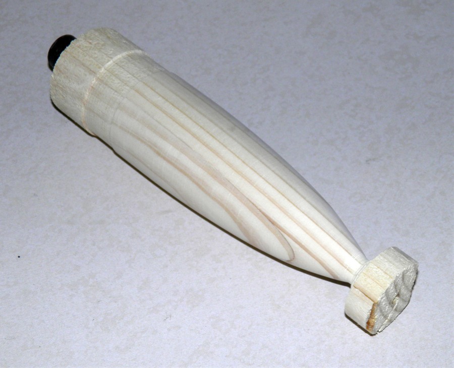
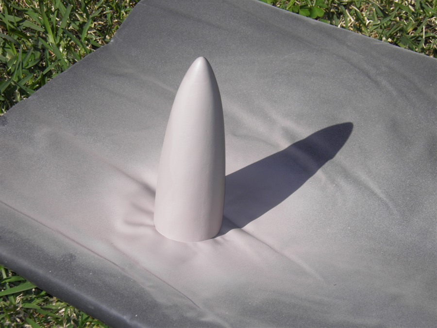
14 September 2011 - Spent
about an hour and a half machining the
nosecone plug down to the right shape. The
tip will be made separately because it is
difficult to lay the fiberglass over the
tip.
Rough cut to correct dimensions
Sanded and almost finished.
Ready for trimming
Trimmed base and tip. The tip of
the nosecone will be made
separately
We also glued in the
other plug but with regular Araldite. We used a little water
and bubble bath mixture and coated the
inside of the tube and the o-ring so that it
would slide in easier.
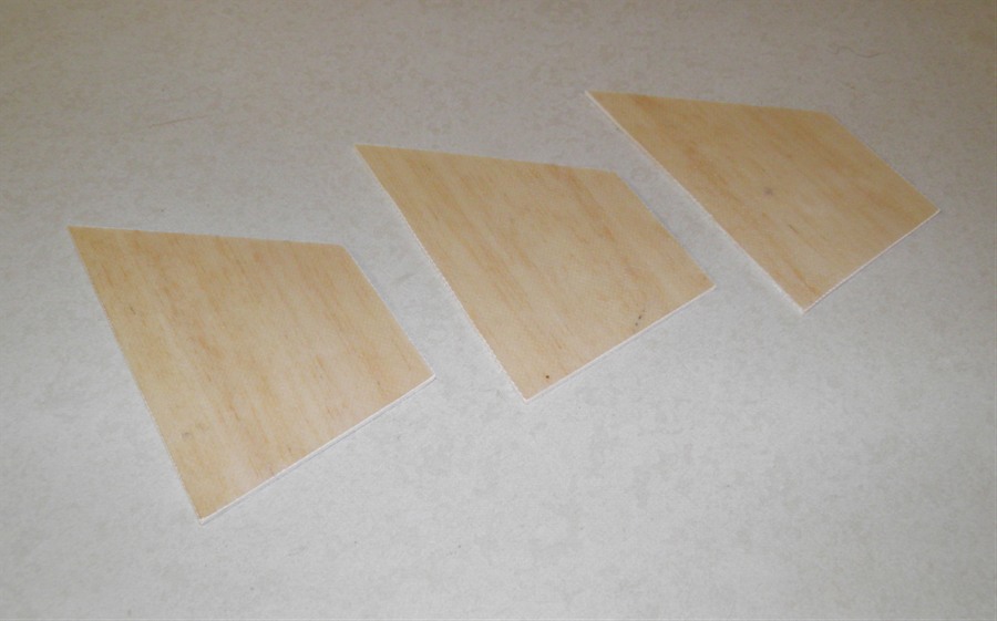
The fins were cut out
of the balsa sandwich and seem reasonably
strong. They may break when the rocket lands
though. Each fin weighs 14 grams.
Balsa sandwich cured....
.... and cut up into fins
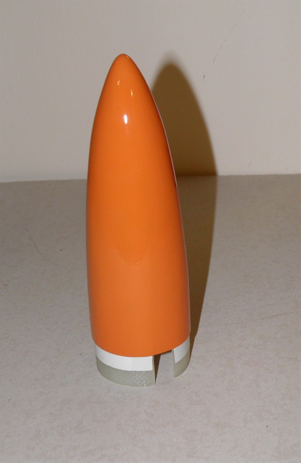
15 September 2011 -
We painted the nosecone plug with the first
coat of the clear 2 pack paint (Wattyl
Estapol 7008). This is a hard
wearing paint we are using to protect
the plug.
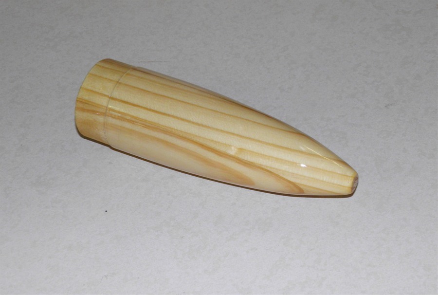
16 September 2011 -
We sanded the
first coat with a 1000 grit sandpaper and
applied a second coat of 2 pack
paint on the nosecone plug. It's all
nice and shiny and smooth now.
Second coat cured on the
nosecone plug.
We also have decided on
a different approach to the parachute
deployment today. There were a number of
issues with the piston spring mechanism
that would have made things a little
more complicated, and it relied on a
couple of elements that needed to be
precision made. Depending on how this
alternative works out, we may still come
back to the piston ejection design.
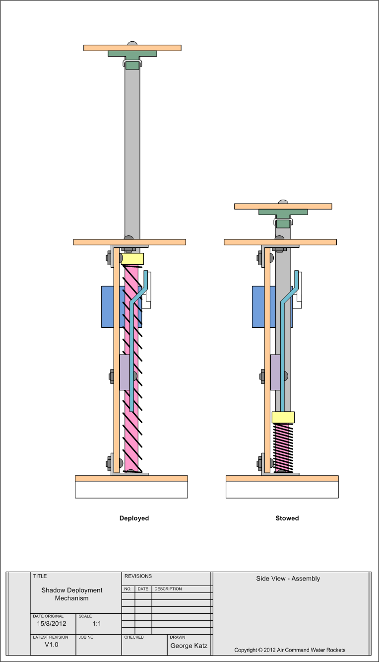
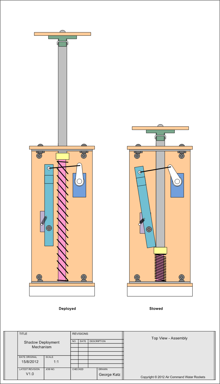
Due to the size of the
air frame we have decided to build what
we are calling the 'Pivot' deployment
mechanism. The design is
intended to be clean aerodynamically and
be able to withstand the high
acceleration forces. The design also
allows the parachute shock cord to be
attached solidly to the air frame in a
convenient place (something that is a
bit of an issue with piston ejection).
The rest of the shock cord will be
located in the empty nosecone. The
design also lends it self to larger
parachutes.
17 September 2011 - Finished the
nosecone plug, and polished it with
carnauba wax mold release. Then
applied a layer of silicone grease and
stretched a normal party balloon over the
plug. Then applied another layer of
silicone grease and stretched another
balloon over that. Then repeated with a
third balloon, but did not cover the
outside of the last one with silicone. I
drilled a hole
in the bottom of the plug so I could
mount it on a bar which made it easier
to rotate while laying up the fiberglass.
We applied about 4 strips of 200gsm
cloth around the plug and then covered
it with a further 9 strips of 85gsm
cloth for a smooth outside finish. The
whole plug was then stood on its end and
let cure for about 6 hours at a temp of
around 20C. I then put it in the car for
another 2 hours as it was around 35C in
there. By the evening it was hard enough
to work on. We had to cut off the base
of the fiberglass with a sharp knife as
there is a small recess on the plug and it wouldn't
have come off.
Second balloon placed over the
plug
Third balloon stretched over the
plug.
Fiberglass strips ready to be
applied on the plug.
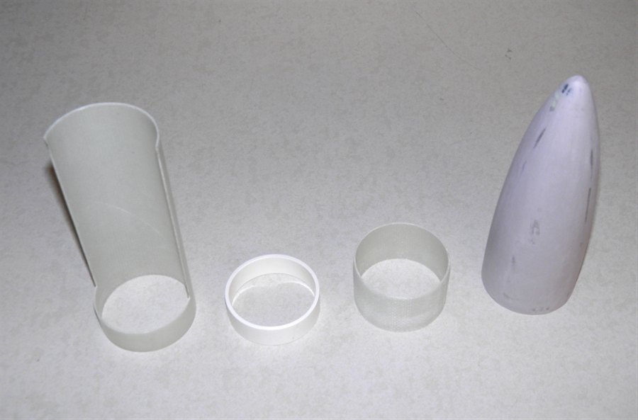
After curing, the tip and base
have been trimmed.
The nosecone slid off
very easily. :) The
base and tip were then neatly trimmed.
We machined the tip from a piece of
plastic and epoxied it in place. We
roughly sanded the outside of the
nosecone, but it will need further work
before it is finished.
Removed from the plug. Leopard
spot design
on the 1st balloon.
Wouldn't be a bad nosecone paint
job. :)
Base of the nosecone sanded.
Tip machined from plastic
fitted,
with nosecone roughly sanded.
We also pressure tested
the tube today now that it has had at
least 3 days to cure. We took the tube
up to 300psi (20.7 bar) and paused to see if there
were any leaks and all was good. We then
took it up to 380psi ( 26.2 bar ) and the top end cap
blew out. The only damage done was to
the PVC support ring that was split on
one side. The plug and tube were
undamaged. You could clearly see that
all the glue stayed attached to the
tube, and almost none of it stayed
attached to the PVC ring. This end cap was
glued in with the West Systems epoxy,
but I also put on a fairly thin coat on
both the surfaces. The grooves in the
PVC were also quite shallow compared to
the other end. The other end was glued
with the normal
super strength
epoxy.
The test also showed that the
tube withstood at least 380psi. By far
the highest to date. We also used the
big gauge and direct connection to the
scuba tank for these tests as the panel
can only go to 300psi.
High pressure connection to
tube under test.
Tube full of water ready to be
inserted into
the scuba tank for testing.
At 380psi the PVC ring came out
and cracked.
The tube and end cap were not
damaged.
18 September 2011
- We spray painted the nosecone with 3 coats
of spray putty and then sanded it back to a
smooth finish again.
20 September 2011
- We machined up a new PVC support ring
and this time cut much deeper grooves in
it for the epoxy. The end of the
fiberglass tube was cut off to remove
the section where the glue remained
inside the tube. We then glued the new
ring in place with the super strength
epoxy. We'll give it a full 3 days to
fully cure before hydro testing it
again.
New PVC support ring with deep
grooves
Glued into place
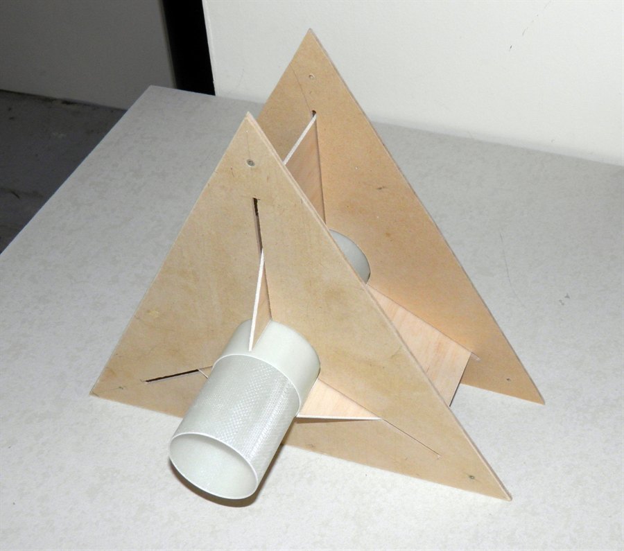
We also started
prototyping the pivot deployment
mechanism tonight. This was basically a
test to see how it would go together and
how it holds up structurally. So far it
looks fairly good so we'll continue with
the next step and try to get the
prototype to work. The one thing we are
always mindful of are the acceleration
forces as well as any wind sheer forces
after we've had a few high speed
failures with other designs. The
nosecone is attached to half the payload
bay, and the other half the payload bay
contains the electronics and release
mechanism. The pivot point will be at
the bottom of the payload bay with the
release point at the top of the bay. A
spring behind the parachute will force
the nosecone and payload bay to fall to
one side once released, pivoting around
the lowest point. The pivot is not shown
in these photos.
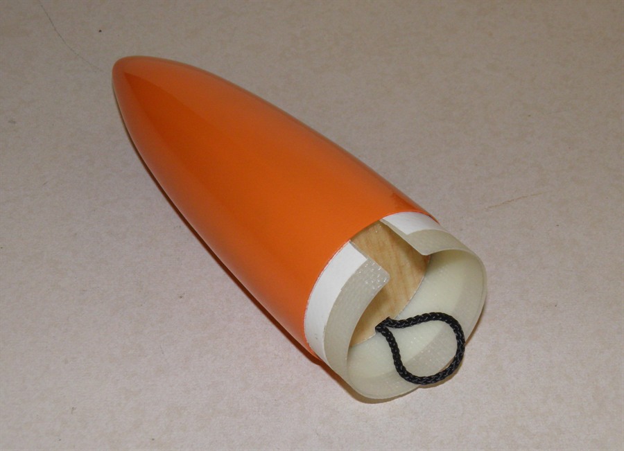
The hollow nosecone is
most likely to store the shock cord for
the parachute.
Prototyping pivot deployment
mechanism
The parachute is stored
vertically.
The top section including the
nosecone will
separate from the rest of the
rocket.
24 September 2011 - Now that the
epoxy has had at least 3 days to fully cure,
we did a hydrostatic pressure test. We
pushed it up to 560psi (38.6 bar)
without leaks and without bursting the tube.
The end caps held up really well too. This was a lot higher than we were
expecting. We stopped the test because the
hoses aren't rated to very high pressures
and so rather than risk bursting a hose
we stopped. We are quite happy with the
results, and this will allow us to continue
development.
Prior to hydro test
Direct connection to the scuba
tank for
higher pressure tests.
Tube and end caps still
holding at 560psi.
27 September
2011 - Machined a smaller mandrel from
the 60mm PVC pipe to allow us to make
fiberglass couplers. We had to machine a
wooden plug first for the tube so that we
could support one end in the lathe. The
mandrel was sanded smooth. We then wrapped
~140cm of the 200gsm cloth on the mandrel.
We used minimal epoxy (1 pump) for this in
order to leave a coarse surface texture
which will be used to hold glue when we glue
it in place. The exact dimensions are not
yet known. We'll have to wait until the
morning to test it inside the body tubes.
Machining the smaller mandrel
for couplers
Laying up a coupler.
The surface texture is made
coarse
to enable easier gluing in the
body tubes.
28 September
2011 - Removed the coupler from the
mandrel and trimmed the ends. The coupler
was just a little bit oversize, but with
sanding it was possible to insert it into
the tube a little. It would take a quite a
bit of sanding to get the whole coupler in
though. So we made another coupler tonight
that used 2 less wraps of the glass. This
should make it easier to insert into the
tube. The glass cloth was 100cm long and we
still used one pump of the epoxy. We'll wait
until tomorrow again to take it off the
mandrel and test it to see how well it fits.
29 September
2011 - After trimming the rough edges,
the coupler fit inside the tube, but seemed
just a little too loose. So we decided to
have another go and made a coupler with 6
wraps. The cloth length was 120cm this time. Back on
the rotisserie it went to cure.
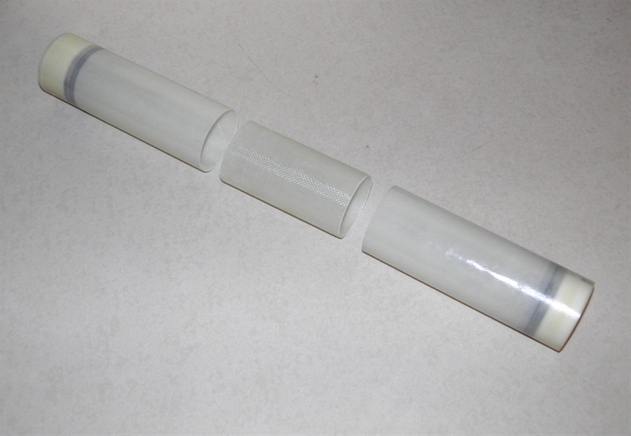
30 September
2011 - Finally this coupler was a good
snug fit into the body tube. We cut it to a
length of 12cm so that 6 cm would go into
either side. It probably does not need to be
this long to hold the tubes together, but
the longer length helps to align the two
tubes. It weighs 42 grams. The left over
piece of coupling will be used to join the
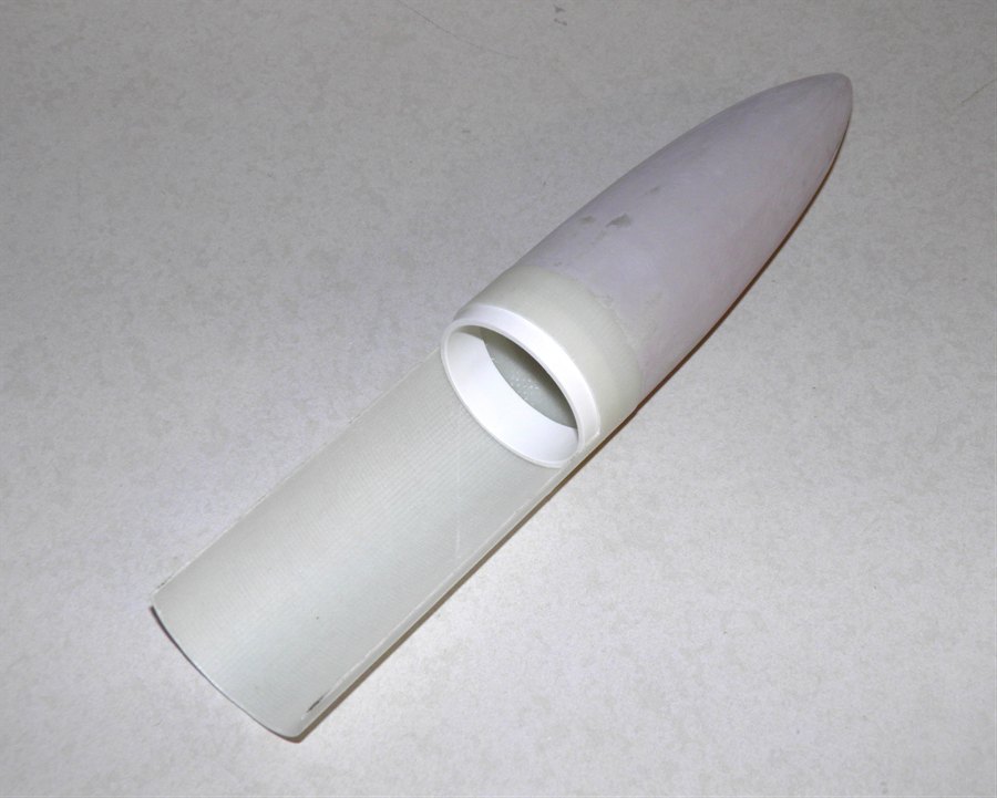
nosecone to the rest of the body tube.
5, 6 and 7 wrap couplers made
for test fitting.
Components going into the
nosecone
section of the deploy mechanism.
Small fiberglass coupler.
Nosecone components assembled.
Today we also bought more of the 85gsm
cloth, but the local supplier does not stock
it in the 965mm widths any more, but only
550mm widths. Dang! So we bought 10m of the
550mm width,
and will roll it length ways to get the
longer tubes. We also bought a couple of
meters of peel ply, so we'll give that a go
to see how well it works and how much
lighter we can make the tubes.
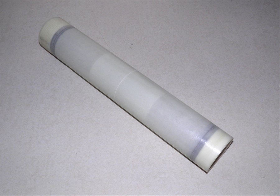
1 October 2011
- We cut the tube we used for the pressure
test in half and will now rejoin it with the
coupler. We'll then again hydro test it to
check for leaks and strength. Due to the
length of the rocket, we will be making it
from two long tubes, and these will be
joined with one coupler.
Test tube cut in half, ready for
gluing
back together again.
Two ends of the tube with
6 wrap coupler
in between.
Tube re-assembled, but not yet
glued.
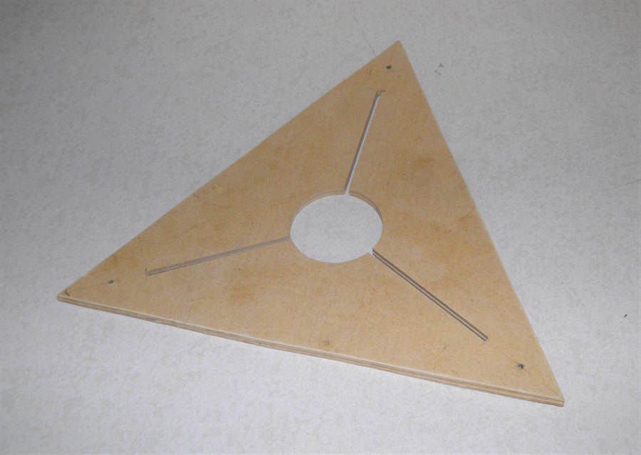
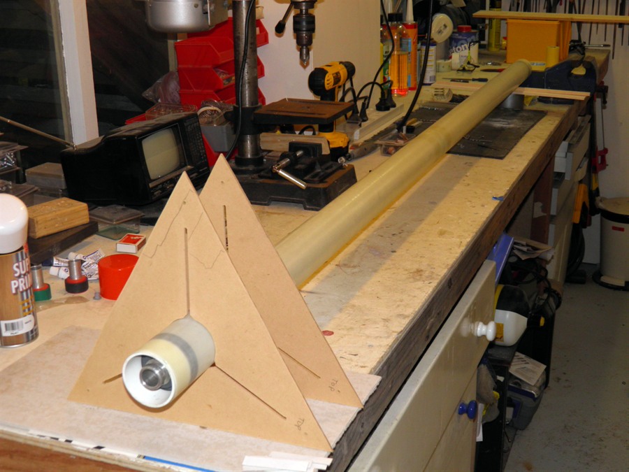
We also made a couple of
fin guides today using a Dremmel tool to
better align the fins on the rocket. We
haven't had a lot of luck usually getting
them aligned by eye so we are taking our
time to do it properly this time. We took a
couple of sheets of MDF and screwed them
together and then cut all the holes and
slots at the same time to make sure they
were exactly the same.
MDF Fin guides.
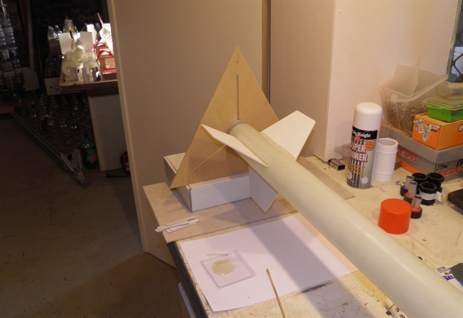
Test fitting fin guides with
fins.
Another view of the fin guides.
2 October 2011
- We glued in the first end of the
coupler today with the high strength epoxy.
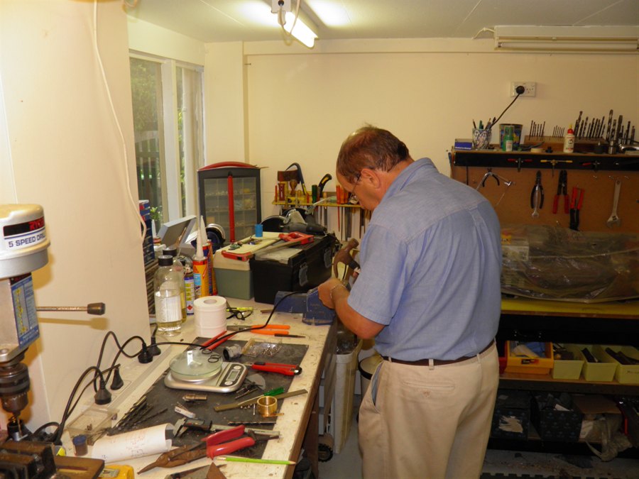
3 October 2011
- We took advantage of the long weekend, and
spent a few hours in the workshop to machine
the nozzle and parts of the launcher. This
rocket requires us to build a completely new
launcher capable of holding the higher
pressures and exactly fitting the new
nozzle. The nozzle thread here is a little
longer than what it will end up. After we do
the pressure test on the tube, we will
machine the hole for the nozzle in the end
plug, and
then cut the nozzle thread to length.
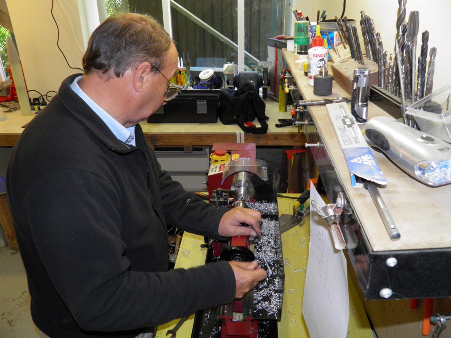
Machining the nozzle from
aluminium.
Dad hard at work.
The nozzle seat is made from brass as it
will be soldered to the copper launch tube,
while the nozzle is made from aluminium to
reduce weight. As is the nozzle weighs 24
grams, but will most likely loose 3 grams.
The nozzle seat on the left and
the
nozzle on the right.
End view of the seat and nozzle.
Nozzle sitting on the seat.
We also glued the other section of the
coupler to the other half of the tube. We will leave it for 3 days
before pressure testing again.
Gluing the two parts of the test
tube back together using the
coupler.
4 October 2011 - We have been looking at
the deployment mechanism again in detail,
and with the expected acceleration profile,
we were getting less confident that the
nosecone would stay in place. So we�re going
back to the piston ejection method
originally considered. This evening we spent
a couple of hours building a prototype to
see how much force and travel we can get
from the piston. The results were promising,
so we�ll build a proper version in the
coming days.
We also bought more copper tube for the
launcher, as well as a 34mm PVC pipe that
will be used as a mandrel for making one of
the launcher components.
5 October 2011 - Fiberglassing
components. Tonight we rolled a thick
fiberglass tube that will form a part of the
release mechanism on the launcher. We also
rolled another coupler that will be used for
the flight hardware. We added a couple of
wraps of the 85gsm cloth to the outside of
the join on the test tube. And lastly we
made up another balsa sandwich with two
200gsm cloths either side. This will be used
to build the main support frame for the
ejection mechanism.
Balsa sandwich, coupler,
reinforced test tube join and
launcher release tube.
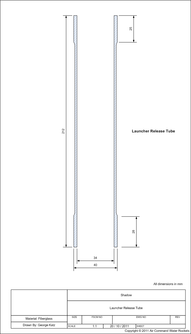
Launcher release tube after it's
come off the mandrel.
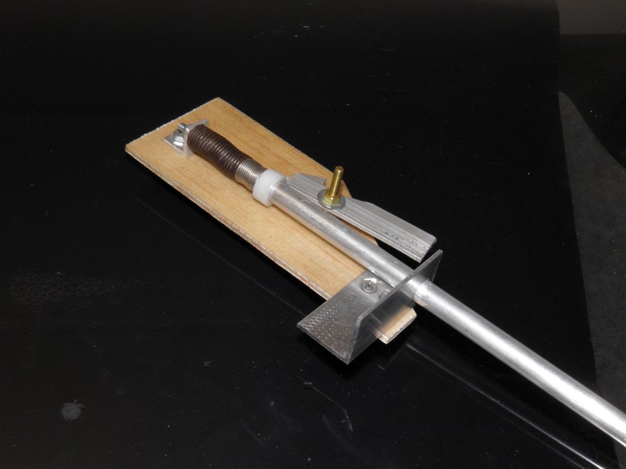
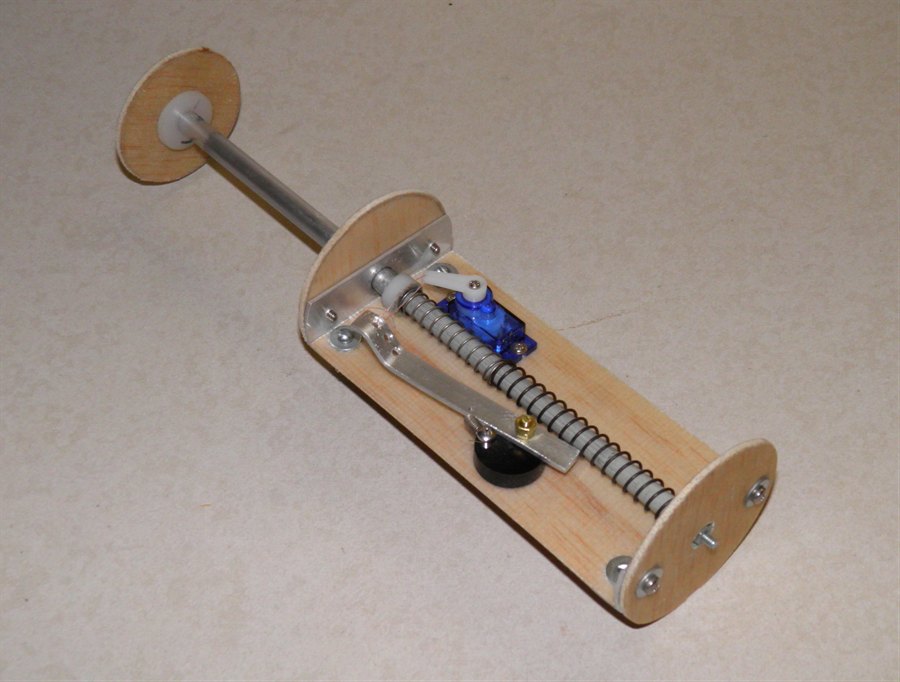
6 October 2011
- Continued to prototype the ejection
mechanism today. The piston shaft is made
from a thin walled aluminium tube. The
piston shaft guide is also made from an
aluminium tube that snugly telescopes into
the piston shaft. The spring is just
threaded onto the piston guide. The guide
extends the full length of the piston shaft
to keep it aligned through the entire stroke
of the piston.
Prototyping piston ejection
mechanism from scraps.
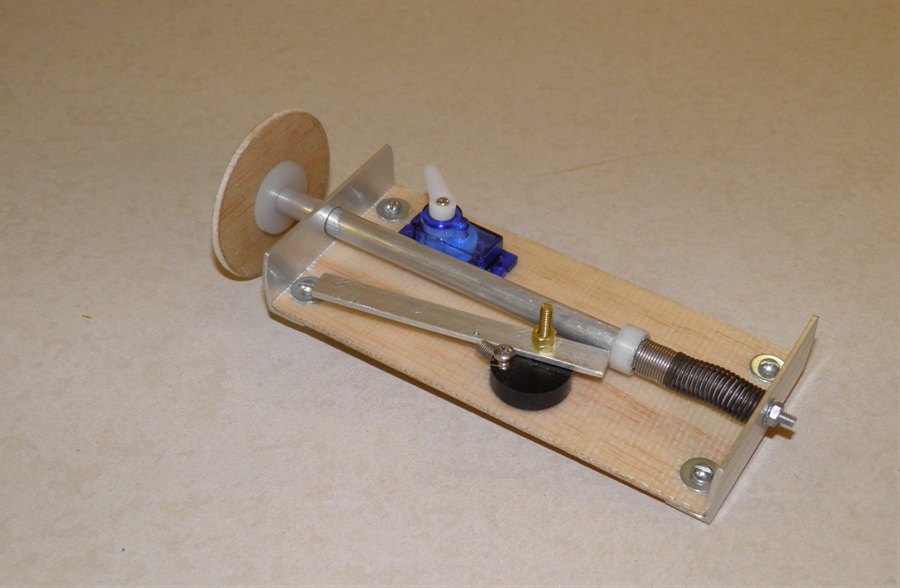
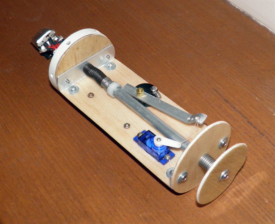
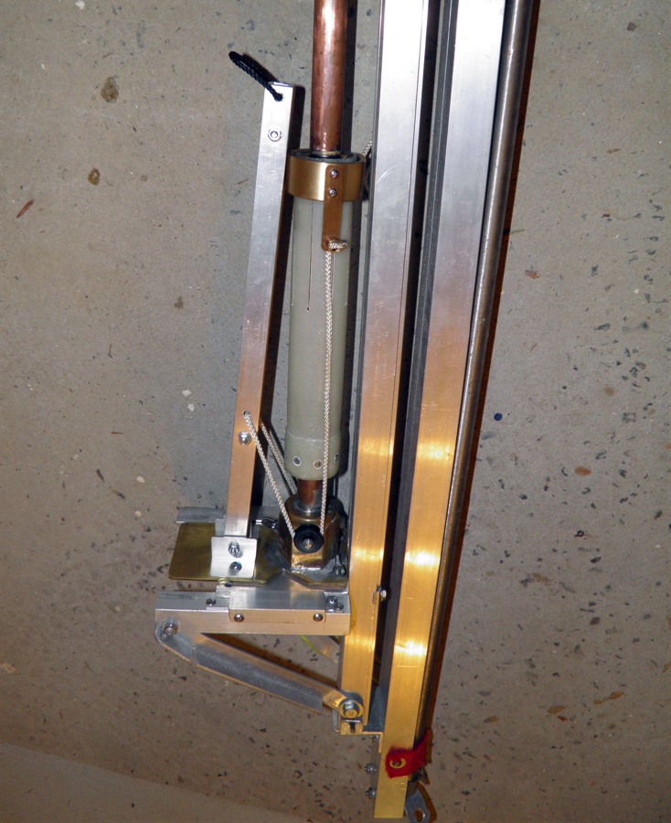
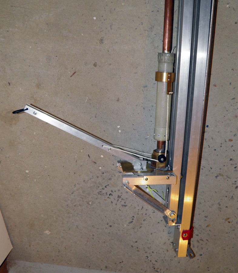
7 October 2011
- Spent a few hours making the flight
hardware for the ejection mechanism. The
system is working quite well with quite a
bit of force to eject the parachute. How it
will work when it's all finally assembled is
still to be tested. We will be triggering
this mechanism using a servo motor, the
Servo Timer II and the uMAD from
Whooshtronics to detect apogee. These will
be mounted on the back of the board. We are
using aluminium brackets here to withstand
the high g-loads during launch.
Ejection mechanism in the stowed
position.
In the extended position.
8 October 2011 -
We hydro tested the rejoined tube today to
500psi (34.5 bar) and the tube held without
bursting or leaking. This is a good result
which means we can now go ahead and build
the rocket pressure chamber. We need to cut
the test tube open so we can get at the end
caps so we can re-use them for the rocket.
Dad also machined two more components for
the launcher today. The release grip ring
and the The release grips will be attached
inside the small fiberglass tube with epoxy
and screwed down with 8 screws. When the
glue is cured we will cut the release grip
ring length ways into 8 sections along with
the fiberglass tube to give us a Clark
cable-tie like arrangement. The bottom of
the tube will be again be epoxied and
screwed down to the other launch tube
adaptor.
Testing the rejoined test tube.
Still holding at 500psi.
Launch Tube adaptor on the left
and
release grip ring on the right.
Surface grooves are for better
glue adhesion
9 October 2011
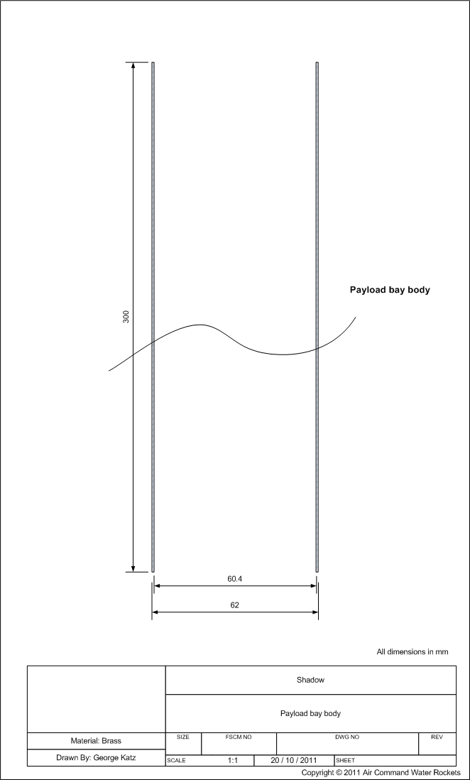
- We rolled the payload bay tube with 7
wraps of the 85gsm cloth. 330mm wide and 660
long x 2. Then used two wraps of peel ply.
The tube weighs 61g for the 300mm. The
surface finish was nice and even but the
texture is a little rough so it will need to
be sanded. The tube is fairly light weight
so the peel ply did it's job. The peel ply
was relatively easy to pull off.
Tube off the mandrel with the
peel ply.
Pulling off the peel ply.
Payload bay trimmed. The inset
shows the texture
We also wrapped
extra reinforcement fiberglass strips to the
launcher tube. We needed to build up the
wall thickness as it will have countersunk
screws in it.
10 October 2011
- We attached the deployment mechanism bulk
heads. These really don't provide any
support, they just keep the whole mechanism centered within the tube. They are also made
from the fiberglass sandwich. The payload
bay tube was trimmed square. We weighed the
entire nosecone assembly with all the
components including parachute and it came
in at approximately 300grams, which is about
the ball park figure we were expecting.
We also experimented with the nosecone
coupling so that it comes off easier. The
coupling itself will be fairly loose but
will have a small strip right near the
nosecone so that it is held firmly, but the
piston only needs to push the little section
before the nosecone is free to move.
11 October 2011
- We tested the deployment mechanism with
the servo controlling the release arm. The
servo is strong enough to activate the
release arm which was a good thing. We tried
to eject the parachute several times, and in
most cases it was getting ejected well, but
on a couple of occasions the nosecone didn't
come off because it was wedged in too tight
into the payload bay tube. We just used
electrical tape on the coupler to increase
the friction between the tube and nosecone
so that it would stay in place. We are quite
aware that the nose cone could drag separate
so we don't want to make it too loose. There
is a rule of thumb in the pyro rocket world that
you should be able to hold the rocket by its
nosecone and the rest of it should not
separate. That's kind of hard to test
without the rest of the rocket at the moment.
:)
Deployment mechanism extended
Deployment mechanism in it's
stowed position
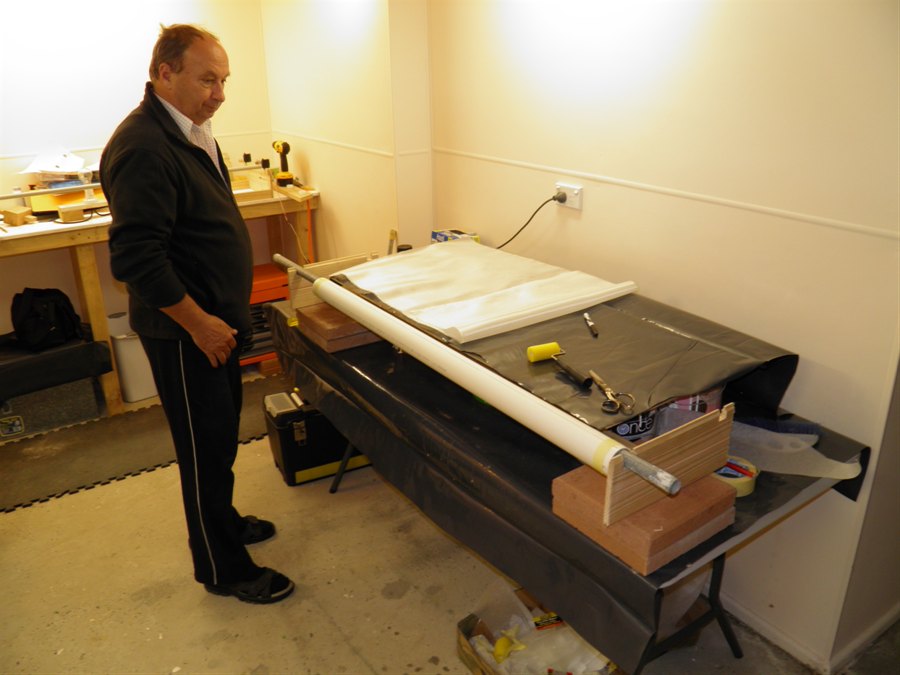
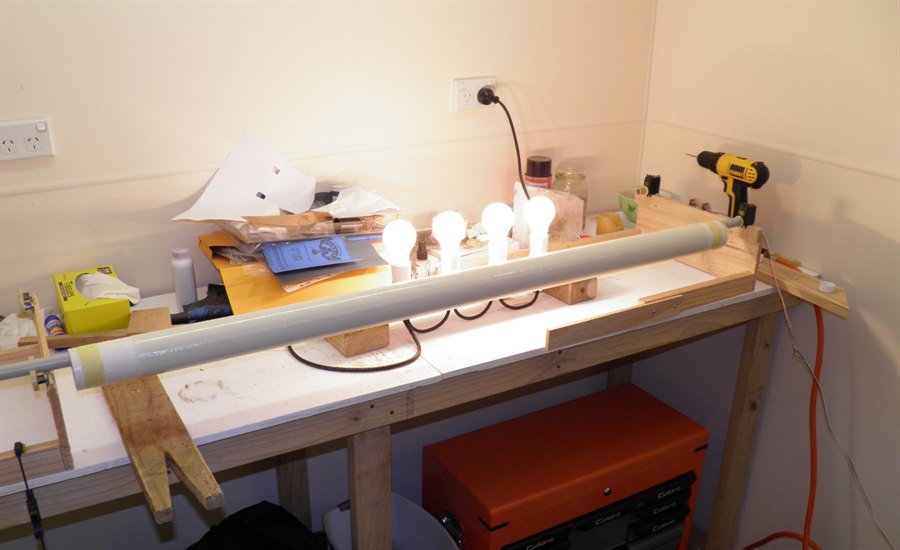
12 October 2011
- The day has finally arrived when we
rolled our first full length tube that will
be used on the rocket. It was made from 3
sheets of 550mm x 110mm 85 gsm cloth. We
used exactly 6 pumps of the West Systems
epoxy. This was enough to give the tube a
reasonable finish that will require some
sanding but not too much. We had to work
quickly to get it done before the glue
started to set. The whole thing then went
onto the rotisserie for a couple of hours
and then the mandrel was stood on it's end
to try to keep it straight while the epoxy
cures. We'll leave it for 24 hours on the
mandrel before attempting to remove it.
Because we only had the heat lamps set up
for short tubes, we had to move the lights
every 10 minutes so the whole tube was
evenly heated.
Getting ready to roll the first
full length tube.
Tube on the rotisserie.
We
also measured the ejection force of the
deployment mechanism. Just as it releases it
is pressing with about 3.2Kg onto the
nosecone. Which is probably not quite enough
force to be reliable. We stretched the
springs a little, but that didn't help much.
We are going to try to find a stronger
spring so that we can get up to around 5Kg
of force. Still the way the system is
working with the current springs is that it
shoots the nosecone about 1 meter from the
rocket.
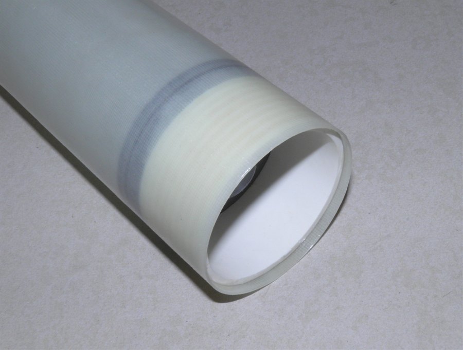
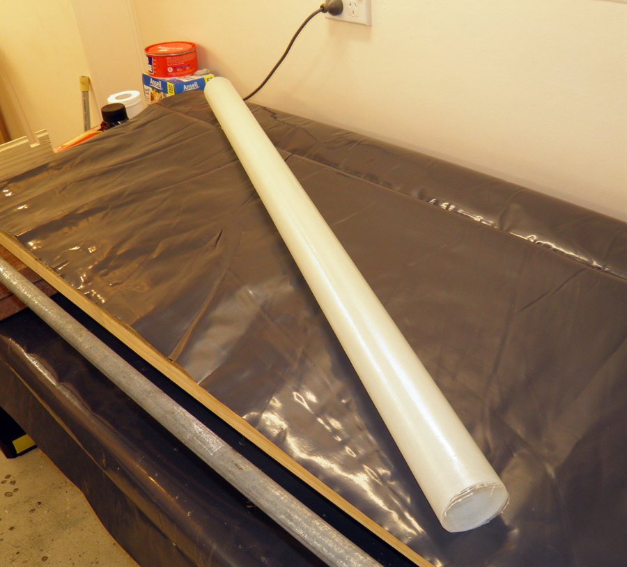
13 October 2011
- Took the long tube off the mandrel today
without any issues. At 1110mm it weighed in
at 325grans which is about 20 grams heavier
than originally thought, but there is a
little more glass on it - about 50mm more
and also a good amount of epoxy, but at
least it is stronger. We're quite happy with
the result because the tube is nice and
straight and is quite strong. One of the
biggest concerns was that it would be
flexible - a major issue with our previous
FTC experience. We'll give it a few more
days to cure and then we'll sand it trim and
sand it.
Tube off the mandrel with the
glad bake removed.
15 October 2011 -
A busy day today. We machined the fiberglass release tube
to make it nice and round at the ends. We
also
cut up pieces of the copper tube for the launcher
release mechanism. Although after looking at
the pipes we may change the layout a little
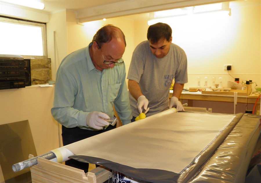
bit. We also rolled the second long tube.
Launcher components with
fiberglass
tube on the right.
Rolling the second tube. Dad
pours the
epoxy while I roll it out.
Definitely much
easier with two people.
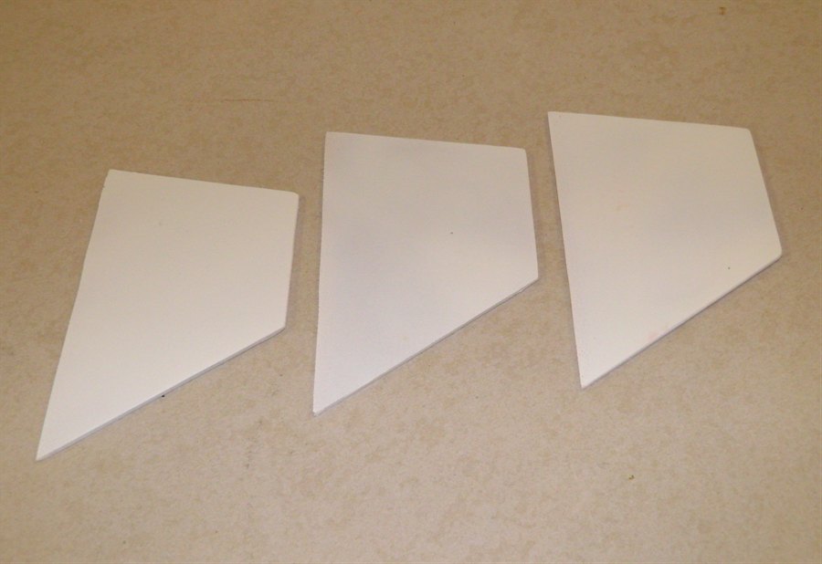
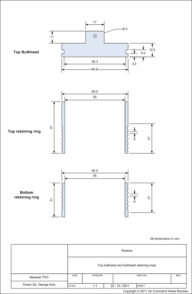
End plug retainer rings
Then dad took the test end plug and machined
the nozzle thread into it. We also tapered
the internal wall of the end plug towards
the nozzle opening to let the water and air
flow easier.
Aluminium nozzle screwed into
the
PVC end plug.
The inner edge of the nozzle is
rounded
for better flow efficiency.
Side view
16 October 2011
- We made another coupler as the one we
were going to use was a little tight and
would have needed a lot of sanding. It was
just easier to roll a second tube. This
coupler was made from
2 x 550mm pieces of 200gsm cloth and used 1 pump
of the epoxy. We sanded and trimmed the main
tubes. The two tubes weighed in at 308 and
297 grams.
Two sanded main pressure chamber
tubes.
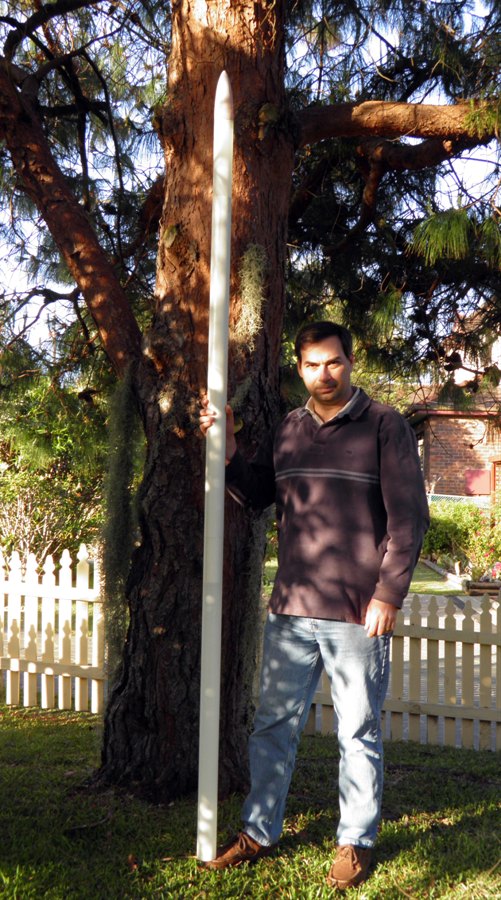
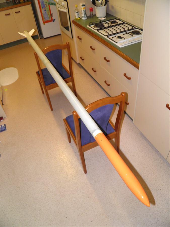
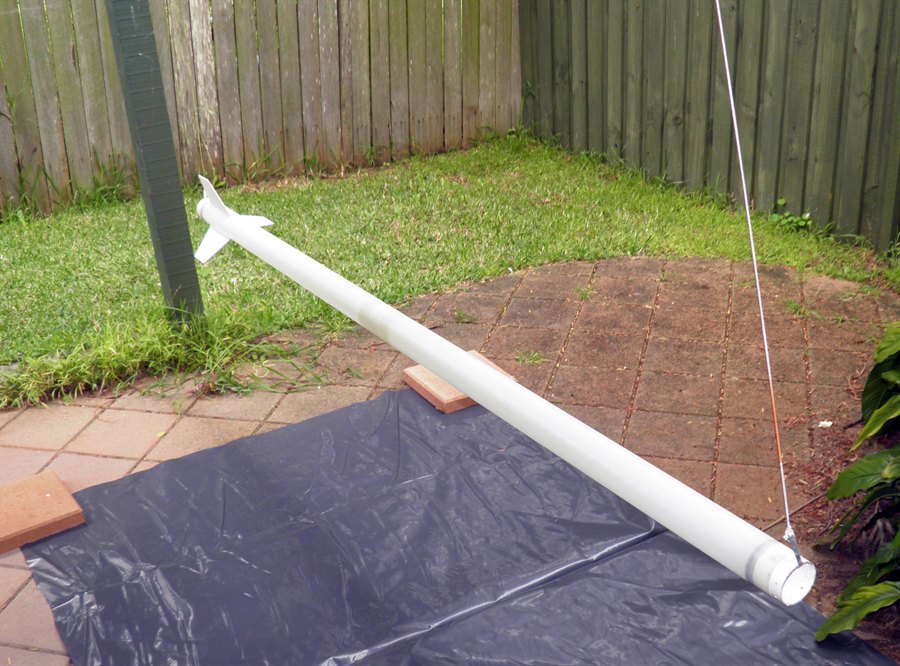
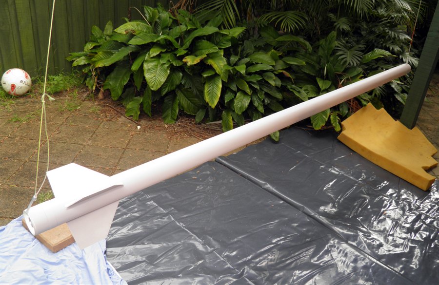
18 October 2011
- We sanded and trimmed the coupler. The
coupler weighs 42 grams. Putting together
the two tubes, the payload bay and nosecone
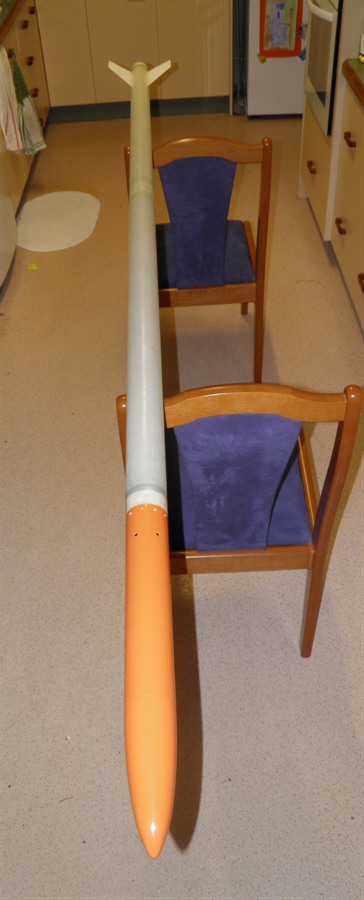
we get a rocket length of 2580mm or 8.5
feet.
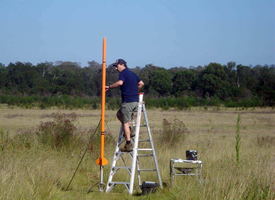
It doesn't look that big here,
but it looks big in real life.
19 October 2011
- Before gluing all the components together
I spent some time doing up the tech drawings
of all the components. Even though we had
the original tech drawings from which we
made the components, decisions are made
during manufacture that will deviate from
the original drawings. This way we have the
exact dimensions of the final components
should we need to make them again.
20 October 2011
- We wanted to get the ends of the tubes
nice and square so that the whole rocket
goes together straight when assembled.
Because the tubes were too long to fit on
our lathe, we set them up on the rotisserie
and had them turn slowly, and then we
solidly mounted the dremmel with a sanding
wheel and let the dremmel grind the end of
the tube as it rotated. This gave very good
results. We trimmed both ends of the tubes
as well as the payload bay tube.
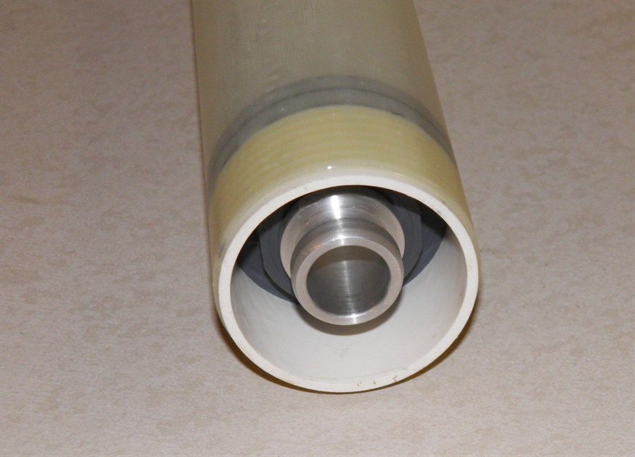
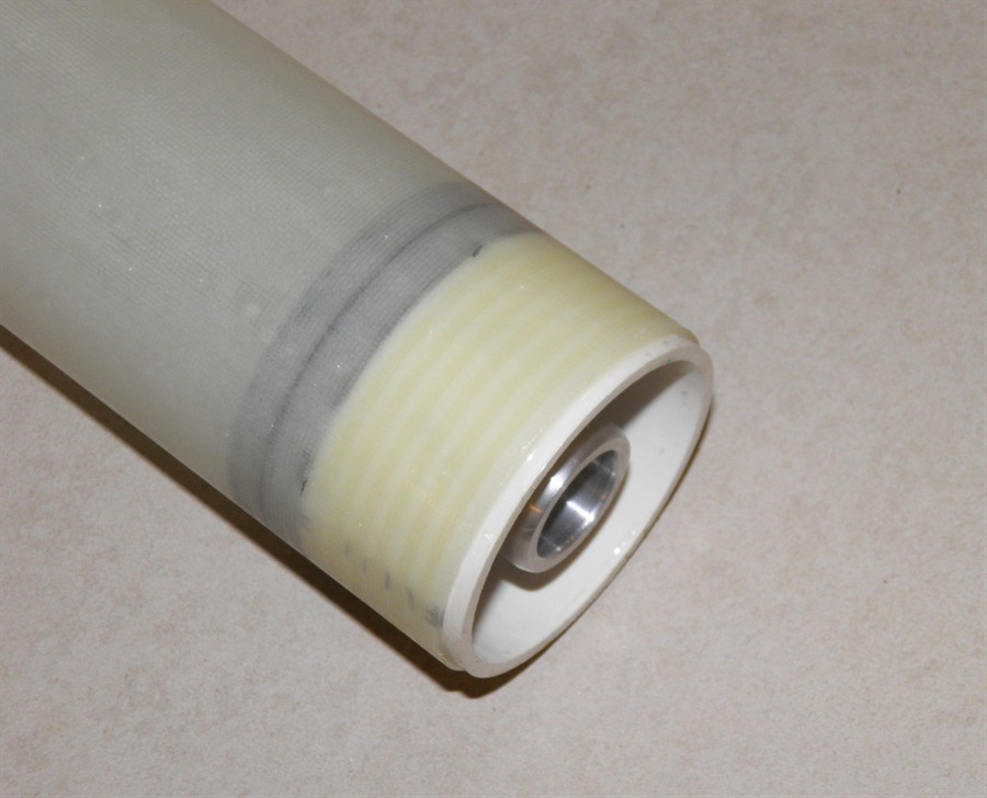
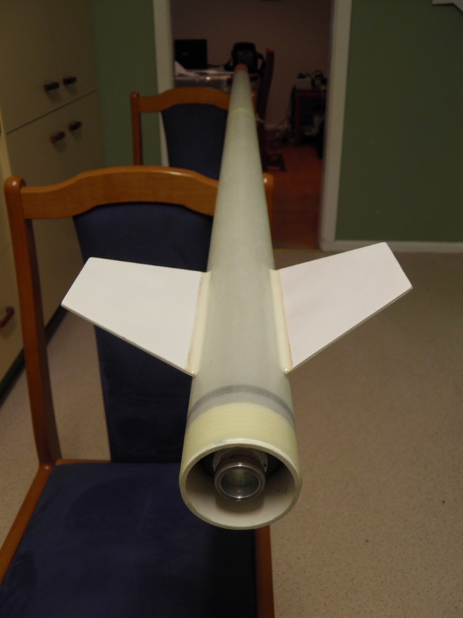
21 October 2011
- We glued the endcaps into the tubes in
much the same way as we did for the test
tube with the super strength epoxy. The
nozzle is recessed into the tube so that it
will be protected when the rocket lands tail
first. The top retaining ring extends past
the top of the tube to allow the payload bay
to be mounted. This will most likely be
attached with a set of screws.
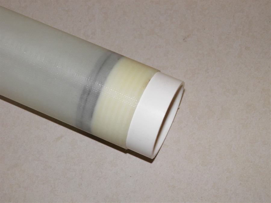
Nozzle glued into place
The retainer ring extends past
the bottom
of the nozzle to protect it
during landing
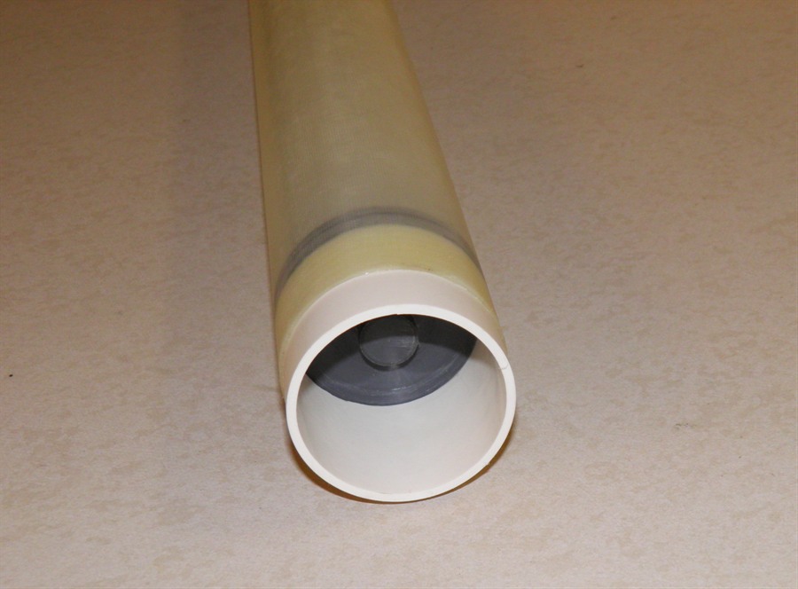
Top endcap glued into place. It
extends
above to allow the payload bay
to be
attached.
End view of end cap.
22 October 2011
- We sanded down the new coupler for a nice
snug fit, and trimmed the edges nice and
square. We also glued the retaining ring
into the fiberglass release tube with the
super strength epoxy.
Retaining ring glued into
position
Fiberglass launcher release
tube.
23 October 2011
- Dad came over to work on the launcher base
and release ring.
We are using our old Medium launcher as the
base for this launcher, but it will be
fitted with the new release head.
Launcher base components
The solid base will be attached
to the bottom
of the launch tube.
The two components will be
soldered together.
The release ring is made out of a 4mm
thick brass ring. This should be strong
enough to hold the pressure. It will be
interesting to see how easy it is going to
be to pull back under pressure. We will
again have a lever to make the job a little
easier.
Launcher release ring.
6 November 2011
- We glued the coupler into one of the
pressure chamber tubes with the super
strength epoxy. We also cut the 16 1/8"
threads into the release head and counter
sunk them. Along with that we cut the screws
to their correct length. These will be
epoxied in place. They are there to serve as
a backup to make sure the segments of the
retainer ring don't come off under pressure.
Each of the segments needs to hold about
12Kg. We then cut the retainer ring into
segments and the top portion of the
fiberglass tube into strips. We were happy
that the retainer ring fit well over the
nozzle as we haven't been able to test it
until now that it was cut up. The release
ring also fits well over the release head
and seems to be releasing just fine. We'll
see how well that works under pressure.
Tapping 16 holes in the retainer
ring.
Screws cut to length
Slots cut into the fiberglass
...
... and retaining ring. Each
segment
can now flex back to release the
nozzle.
We also worked on the launcher base and
soldered together the riser tube, the base
plate and the air manifold. We also made a
pair of pulleys for the release rope. The
release ring also now has a pair of brackets
to attach the release rope to. We had to do
this as the release ring slides almost
entirely inside the rocket.
We are going to have to pressure test the
rocket at the same time as the launcher as
they are both needed by each other to make a
seal.
Launcher base and air manifold
soldered together.
Release ring with brackets.
8 November 2011
- We glued the pressure chamber together
with more super strength epoxy. We used 3
right angle 1m long aluminium brackets to
keep the whole joint straight while the glue
cured. The whole pressure chamber was kept
vertical during the curing process to keep
any internal runs of glue evenly spread.
We also glued in the screws for the
release head to make sure it is as strong as
possible.
Gluing the pressure chamber
into one piece.
We used Aluminium right angles
to
keep the joint nice and
straight.
Screws glued in place.
9 November 2011
- We drilled and cut threads for the release
tube spacer. This spacer will be soldered to
the launcher tube first and then when
everything is aligned we will epoxy the
fiberglass tube to the spacer, and also
screw it down with 8 screws. Hopefully that
will be enough.
We weighed the pressure chamber and it
has come in at 833 grams. This is about 90
grams more that initially predicted, but
some of it is likely the result of the tubes
being a little longer. We still need to
measure the capacity of the rocket. Paint will
also add a little more weight.
Test fitting all the components
Pressure chamber almost
ready for testing.
Bottom of the fiberglass tube is
screwed down. Eventually it will
also be glued down with epoxy.
Someone is going to have to
clean
up the mess. ... busy day in the
workshop.
10 November 2011
- We soldered the launch tube and nozzle
seat to the rest of the launcher along withe
fiberglass tube spacer. We also decided that
we would use the quick launcher as the base
for the rocket rather than the medium
launcher, as it meant that we could complete
it sooner and it has certain advantages. At
first I didn't want to use the rail buttons
on the rocket to keep it clean
aerodynamically, but decided that was going
to make other things more difficult. We are
going to attach the rail buttons only
temporarily for the first few flights.
We made an adaptor plate for the quick
launcher and mounted the new launcher to it.
That completes the bulk of the launcher
construction. We still have to add the
release lever to the launcher, but it should
be ready for pressure testing soon.
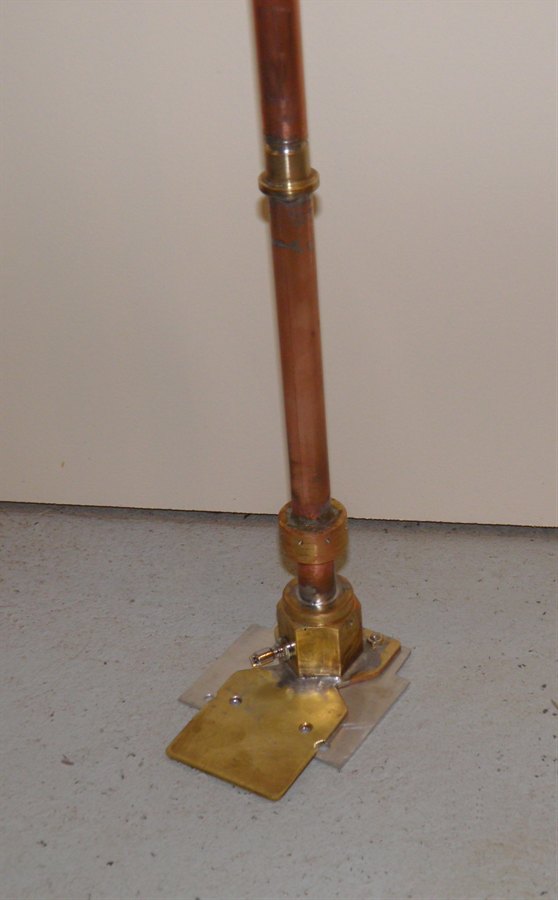
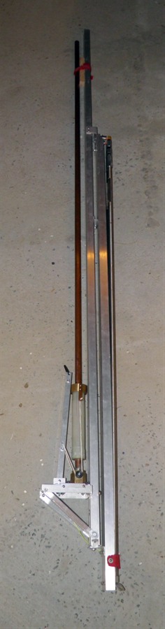
Finished soldering all the major
sections together.
The launcher has a 1.5m long
launch tube.
17 November 2011 - We glued a whole range
of things today. We reinforced the join the
the pressure chamber tube with a couple of
wraps of the 85gsm glass. We glued the shock
cord loop to the nosecone, the shock cord tube to
the payload section. We also glued the
support ring to the ejection mechanism, and
the bulkhead to the nosecone. We also mixed
the epoxy with the micro balloons to make a
paste and filled the holes in on the fins.
In an effort to try to create a stronger
force for deployment, I added a second
spring under the ejection plate as there was
still room. This will help the nosecone
separate, while the existing spring will
push the parachute out.
Loop on nosecone attaches to
shock cord
Carbon fiber
shock cord tube attaches the
entire rocket to the parachute.
A knot at the end
of the shock cord prevents it
from coming loose.
The shock cord tube glued to the inside
wall of the payload bay is intended to hold
the end of the shock cord clear of the
ejection piston. If the shock cord was
attached further down then parachute opening
may pull the cord against the piston and
bend it. This presented a problem of how to
fit the nosecone coupler into the payload
bay tube, and so a slot needs to be cut in
it. The slot produces a little weakness, but
because of the thickness of the coupler and
that it is supported by the bulkhead it is
strong enough.
18 November 2011 -
We attached the sled to
payload bay with 6 x 1/8"counter sunk screws.
These should be enough to support the weight
of the entire sled and parachute during max
acceleration. The parachute and sled will
weigh around 5Kg during peak acceleration.
We attached the servo timer II and uMAD to
the back of the sled and wired them up to a
temporary power supply for testing. I have
some 100mA LiPo batteries on order so we
will use those to power, the uMAD, servo
timer and the zLog altimeter. The altimeter,
HD camera and power supply will all be
located in the lower payload bay.
Servo Timer II and uMAD
attached to the sled
reverse view
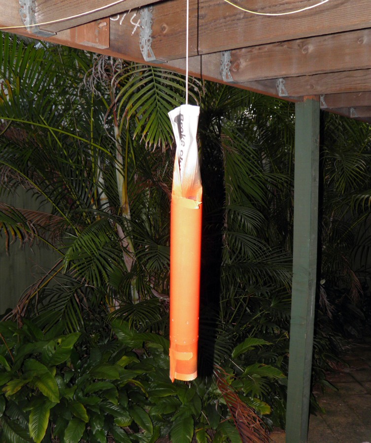
19 November 2011 -
We've put together a video to show how the
deployment mechanism works. It will be
interesting to see how well it actually
works in flight and under high-G conditions.
We do not have a back up parachute
deployment mechanism on this rocket so it's
all or nothing. The springs provide about
50N of force to separate the nosecone. We
have to find a good balance on the friction
fit of the nosecone as too little friction
poses the risk of the nosecone separating
after burnout. (We are expecting around -2G)
Too much friction means that the spring may
not be strong enough with the added air
pressure to push the nosecone off.
20 November 2011 -
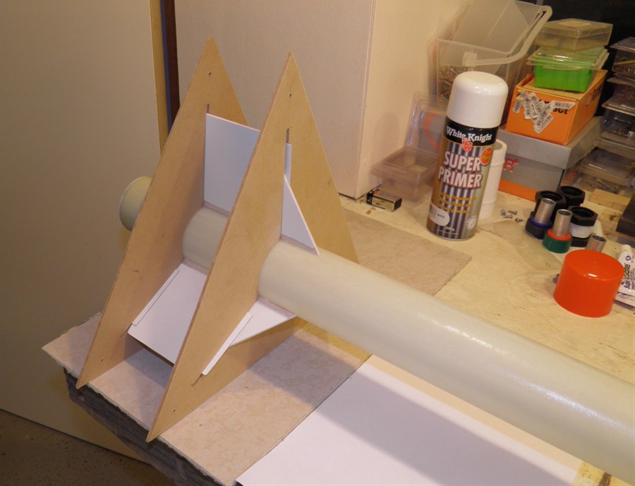
We sanded and painted the fins with primer
today. We also performed the first dry low pressure test of
the launcher and
pressure chamber together. This test was
intended to do a basic leak check on all the
components and seals. We held the 30psi for
about a minute with no leaks. We will need
to do a full pressure test next to see if
the components will withstand the launch
pressure.
Fins painted with primer
Low pressure leak test of
launcher and rocket
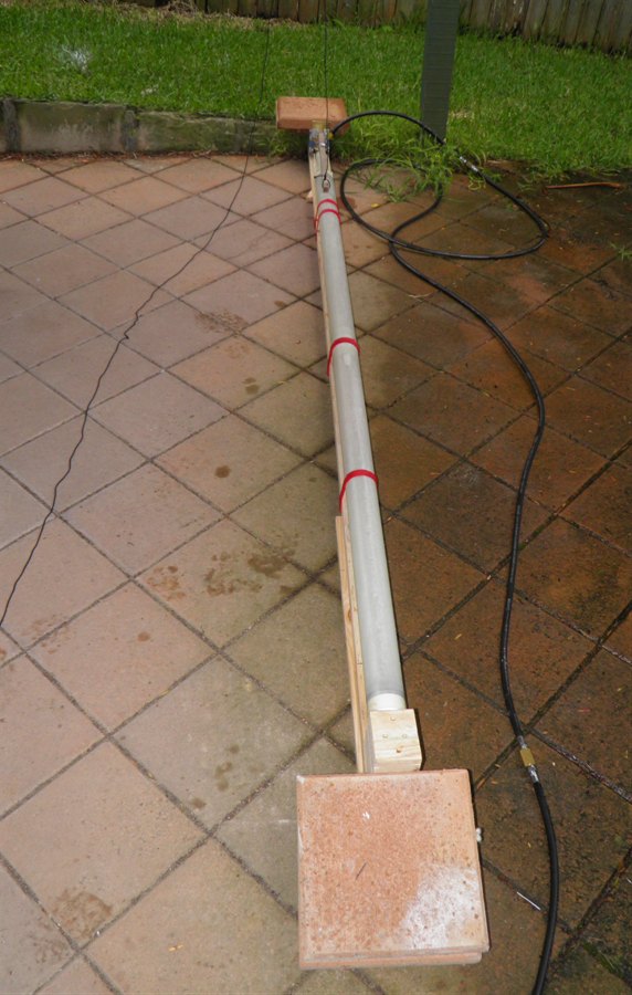
23 November 2011
- Today we made a test stand for pressure
testing the rocket, launcher and release
mechanism. One of the major unknowns is how
easy it will be to release the rocket at the
high pressure. The test stand consists of a
long piece of wood with a stop at either
end. The rocket will be filled with water
and placed on the launcher. This will then
be placed into the test stand and
pressurised. There is just enough room for
the launcher to move about 1.5cm so that
upon release the o-ring on the launcher will
clear the nozzle and allow the water to
escape around the launch tube. At full
pressure the the launcher would be pushed
out with a force of around 1000N.
Rocket and launcher on
the test stand
24 November 2011
- We made a temporary wooden release lever
to pull down the locking ring. We wanted to
get an idea of how hard it will be to pull
back the ring at full pressure. We hydro
tested the launcher and pressure chamber to
335psi and held it there for a while to make
sure it sealed well. We were happy that all
the seals worked as they were supposed to
and the tube did not blow up. This was the
first time we've had a tube this long
pressure tested. The lever was very easy to
pull back and it released the rocket without
a problem. The rocket moved just enough for
the o-ring to come free of the nozzle and
the water slowly drained from around the
launch tube. This was a relief as we
couldn't attach the payload bay or fins
until the pressure test was complete.
We also made a pair of small lightweight
rail buttons that will be attached to the
outside of the rocket.
Temporary release lever set up
for
pressure and release test.
Launch rail buttons to be
attached to
the outside of the pressure
chamber.
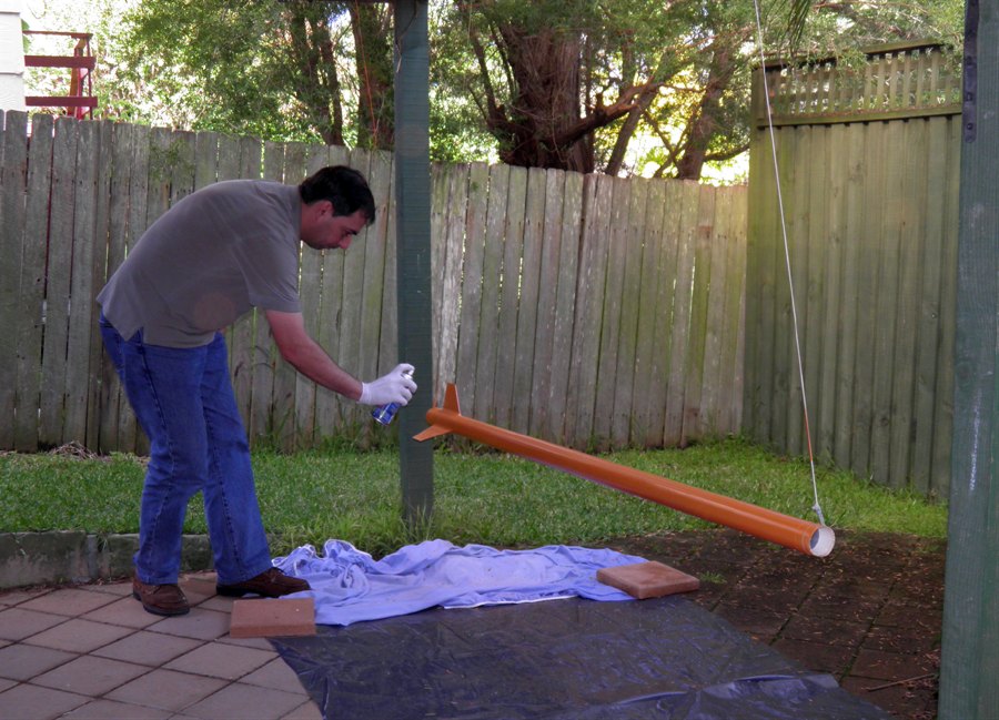
6 December 2011
- We spray painted the nosecone with bright
orange. If it becomes separated from the
rest of the rocket it should be easier to
find. We just used regular Dulux gloss
enamel spray paint.
We also attached the payload bay to the
pressure chamber. This is accomplished with
10 x 1/8" counter-sunk screws. We cut the
screws to length so they are about 5mm long.
We tapped the holes in the PVC ring sticking
out of the top of the pressure chamber.
During the week we also received our
100mAh LiPo batteries that we'll use on the
rocket. The 70mAh ones probably would have
been sufficient, but this way we have a
little more capacity margin without too much
extra weight. Together they weigh only an
extra 4 grams.
Payload bay attachment holes
Prepping fins for gluing. Here
they
are painted with primer.
Painted nosecone
The black loop attaches to the
shock cord
10 December 2011
- We measured the capacity of the
pressure chamber today by weighing the
amount of water that would fit in. The
rocket has a capacity of ~5.8L.
We also started gluing the fins on today. The
fin guides definitely made it easier to hold
everything in place and keep the fins
aligned. It also allowed us to attach all 3
fins at the same time. We put a small bead
of epoxy along the fin edge and then pressed
it into place. After the epoxy cured we
removed the fin guides and used the super
strength epoxy mixed with the micro balloons
to form the first set of fillets. We used
electrical tape as masking tape to keep the
fillets neat.
Setting up the fin guides.
Fins in place held with shims.
Side view
After the glue has cured we add
the fillets.
11 December 2011
- We spray painted the payload bay. The
first painting pass was a dismal failure as
the surface tension on the paint prevented
it
from filling tiny little holes left over by
the peel ply. After the first couple of
coats dried I thought I would just use some
auto putty to fill in those holes and
re-spray it. Turns out the putty is a great
paint stripper! Well after half an hour of
sanding to remove ALL the paint I was ready
to start again. This time I used the spray
on putty and several coats later and sand
with 400 grit sand paper it was ready for
the normal paint.
Painting the payload bay
The business end of the rocket
here you can see the fillets on
the fins
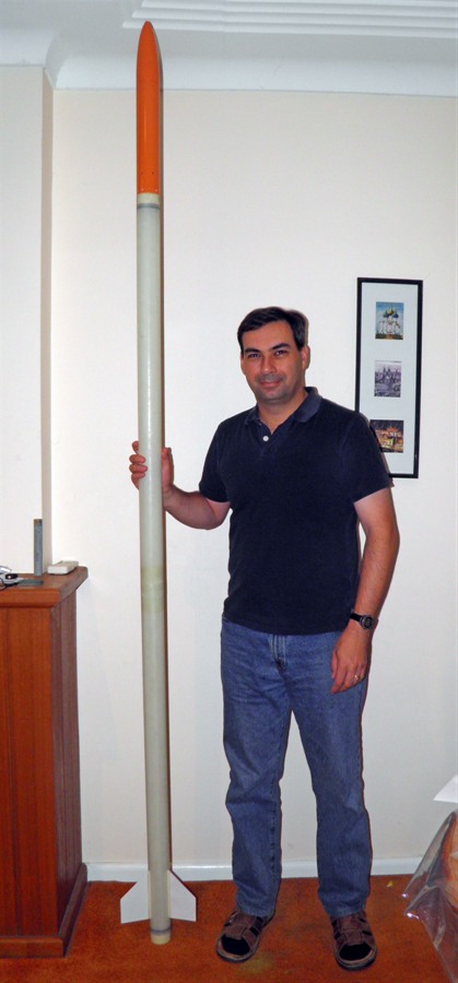
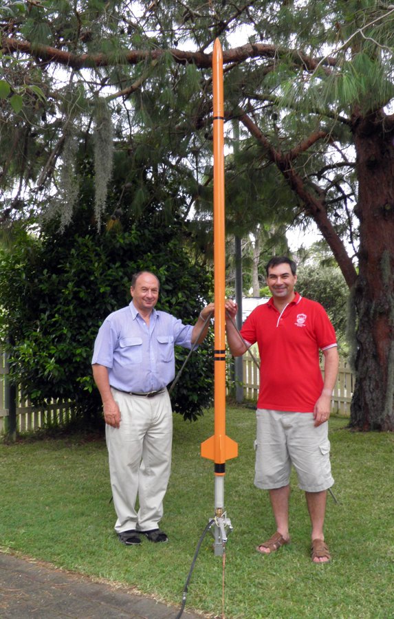
Assembled rocket.
The lower half of the rocket
is not painted yet.
Size comparison.
Another view
We also worked on the launcher to mount a
more permanent release handle. We used the
inside of a couple of electrical connectors
as rope stops so that we could easily adjust
the tension on the pull down string. This
was much easier than making knots in the
string. The launcher is just about finished
with one more little support to be added
that keeps the release ring up until the
rocket is pressurised.
Whole launcher.
Release mechanism in the
locked position.
Release position
17 December 2011
- We washed the rocket with warm water and
detergent to clean it ready for painting and
let it thoroughly dry. We suspended the
rocket on a pair of hooks so that we could
rotate the rocket while painting. After the
adventures of painting the payload bay we
went straight for the spray-on putty. I
think we gave it about 3 or 4 coats and then
let it dry.
Rocket washed with
warm water and detergent
Several coats of spray putty
later.
19 December 2011
- We first lightly sanded the spray on putty
with 400 grit sand paper to give us a nice
smooth finish. The dust was then just wiped
off with paper towels. We spray painted the
rocket body and fins with the same bright
orange gloss enamel as the payload bay. This
Dulux paint has pretty good coverage so only
2 coats were necessary for a good finish. We
also cut the 10 payload bay attachment
screws to size.
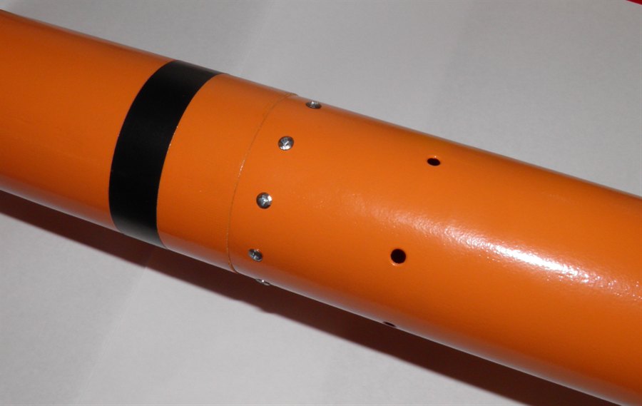
The black band on the rocket is black
tape. This was area was masked while
painting so that we can inspect the o-rings
through the wall of the rocket. This is done
at both ends of the rocket. The middle image
below shows the 10 screws used to attach the
payload bay to the rest of the rocket. The
empty holes are where we attach the deploy
mechanism.
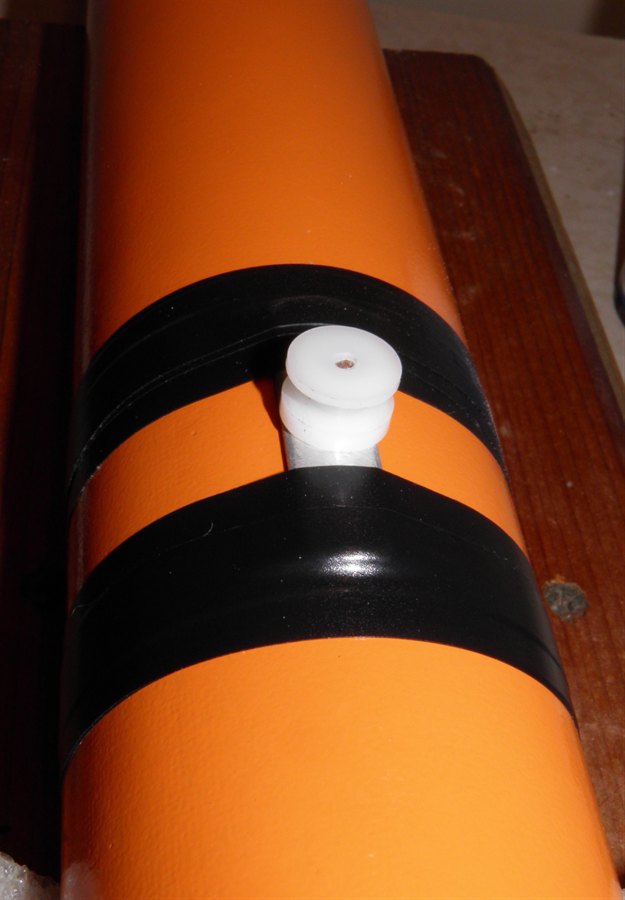
We are only taping the rail buttons on at
the moment to allow us to take them off on
later flights for less weight and drag, as
we will most likely only use the launch tube
to guide the rocket.
Applying the top coats in bright
orange
Attaching the payload bay by 10
countersunk screws.
Rail buttons are temporarily
taped on so later we can launch
the rocket using only the launch
tube
26 December 2011
- With Christmas celebrations mostly out of
the way, we made a short video that explains
how the launcher works and how the rocket is
loaded onto the launcher. The rocket still
needs a few more decals.
Shadow on it's launch pad
4 January 2012 - We reinforced the
shroud line attachment points today.
Previously each shroud line was tied through
a piece of folded over electrical tape, but
we decided to reinforce these because we are
expecting the parachute to open at a greater
speed. We used two layers of cloth tape with
very sticky glue. We are hoping the tape is
stronger than the electrical tape because of
the added fibers. We also put heat shrink
tubing over the loose ends of the shroud
line knots to stop them getting caught on
things.
Reinforced shroud line
attachment points
18 January 2012 - Worked on the
payload bay today. Initially we were going
to use Coriflute to make the payload bay
framework, but then decided to go with 2mm
thick cardboard as it meant we had more room
to fit everything in. The cardboard frame
will be sitting directly on the end cap of
the rocket. We still need to figure out how
we keep it from moving upwards during
deceleration. The camera has been angled
downward since that's where the most
interesting things are to see. We also
pointed the camera directly away from the
guide rail so you could see the launch
string being pulled. We enlarged the hole
around the status LED on the camera so it
was easier to see from an angle.
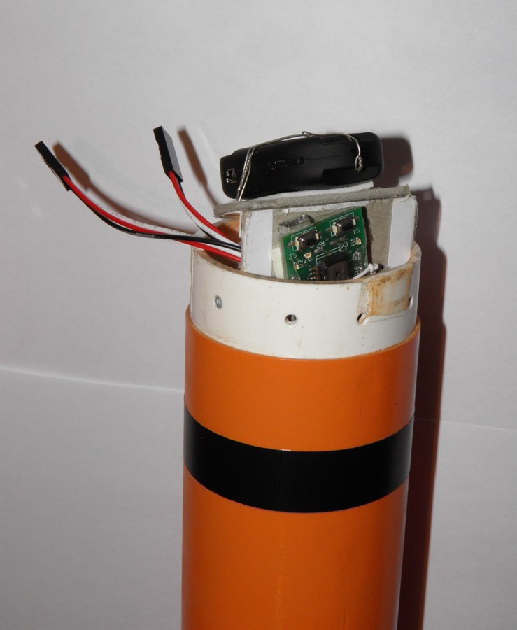
20 January 2012 - Continued to
work on the payload bay framework. We have
fitted the battery, altimeter and camera to
it now. It also has a single power switch
that turns on the servo timer, altimeter and
uMAD. The power source consists of two
100mAh 20C LiPo batteries. We also added a
charging connector to make it easier to
recharge the batteries in place. The uMAD is
powered by one of the cells, and the servo
timer and altimeter are powered by both
cells.
Payload bay with camera on top
secured
held down with double sided tape
and
secured with wire ties.
The z-log altimeter is mounted
at an angle to allow us to plug
in the USB cable. Power switch
is on the right.
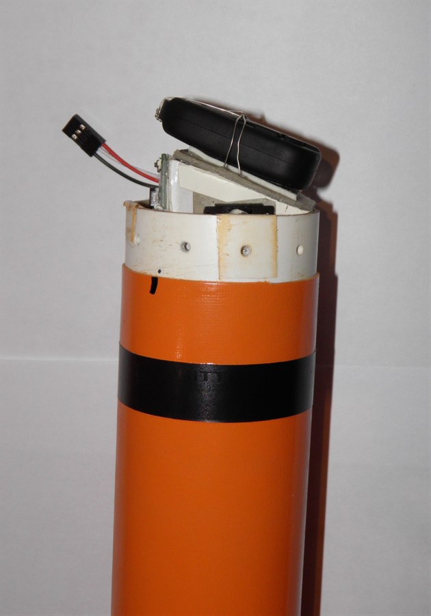
This side has the two LiPo
batteries
and deployment mechanism power
and
recharge connector.
22 January 2012 - After
discussions about how the uMAD is performing
in some directions, we decided that we
should have timer as a backup to deploy the
parachute. Since there really isn't enough
room for a fully redundant system, we
decided to do a firmware upgrade for the
Servo Timer II so that it could be triggered
by both the timer and the uMAD. Luckily it
was a simple change. We have also decided
that the timer should be triggered by the
break wire option rather than the internal
g-switch since we don't know what the rocket
is going to do while pressurising and we
would like to avoid any false triggers if
possible. We also don't know how the built
in G-switch will handle the very high
acceleration, The firmware was updated so
that if the timer fails to trigger due to
some problem with the break wire, the uMAD
should still be able to trigger the servo
timer to deploy the parachute. Having the
extra bit of redundancy should also help if
the high acceleration causes the uMAD to
malfunction.
If you have a uMAD and the STII and are
interested in the firmware update please let
us know and we will send it to you.
Not shown in the pictures below is the
safety line that goes from the top of the
bulkhead, through the payload bay and
connects to the main parachute line. This
line is a backup should the shock cord break
away from inside the tube, or the entire
payload bay gets ripped off the rocket
during a high speed deploy.
Payload bay sitting in the end
of the
body tube. The black band
represents the
location of the top bulkhead.
Here you can see the angle the
camera is mounted at.
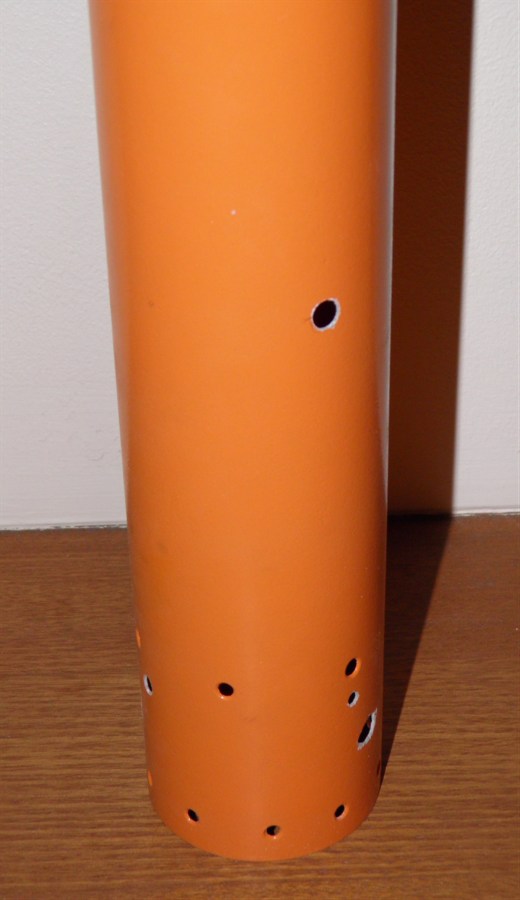
8 February 2012 - We cut all the
holes in the payload bay tube in order to
access all the buttons and switches to
operate the equipment. It's looking a little
like Swiss cheese.
Access holes for the altimeter.
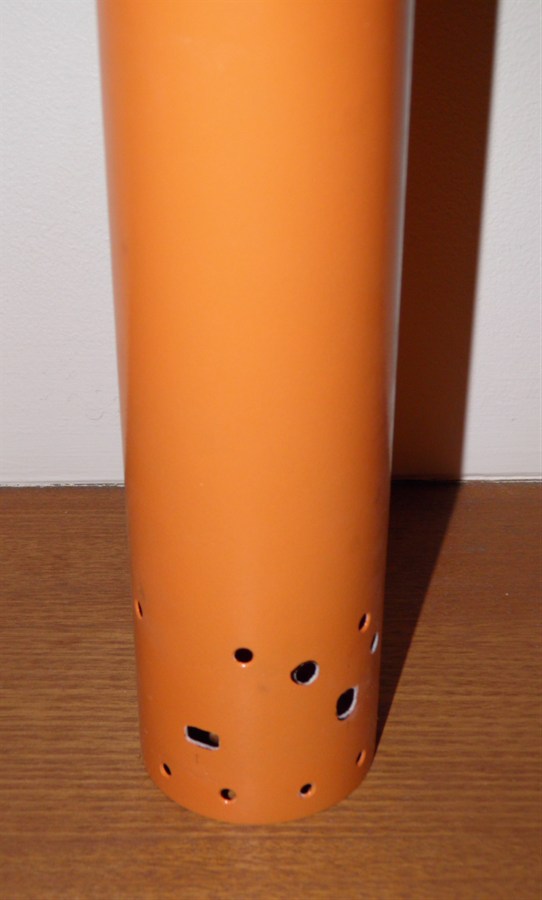
Access holes on the other side
for the power switch and camera.
9 February 2012
- Here are some technical drawings of the
various components used on the Shadow and
launcher.
Top Bulkhead and retaining rings
Nosecone
Payload bay body
Launcher Release Tube
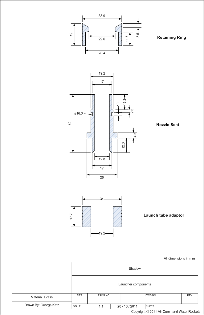
Launcher components
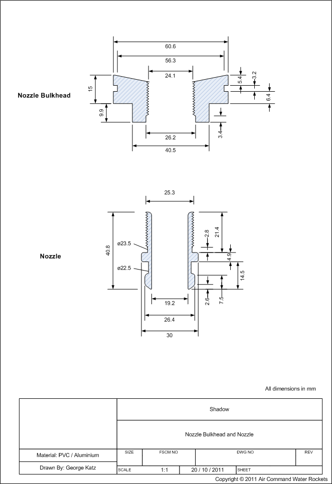
Nozzle Bulkhead and nozzle
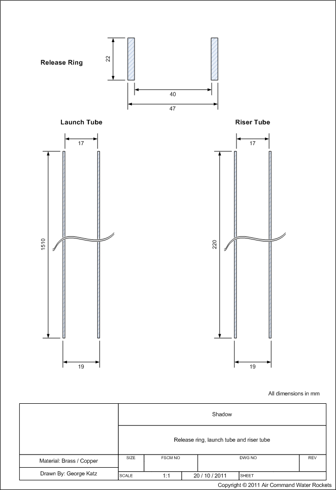
Launch tube, and release ring
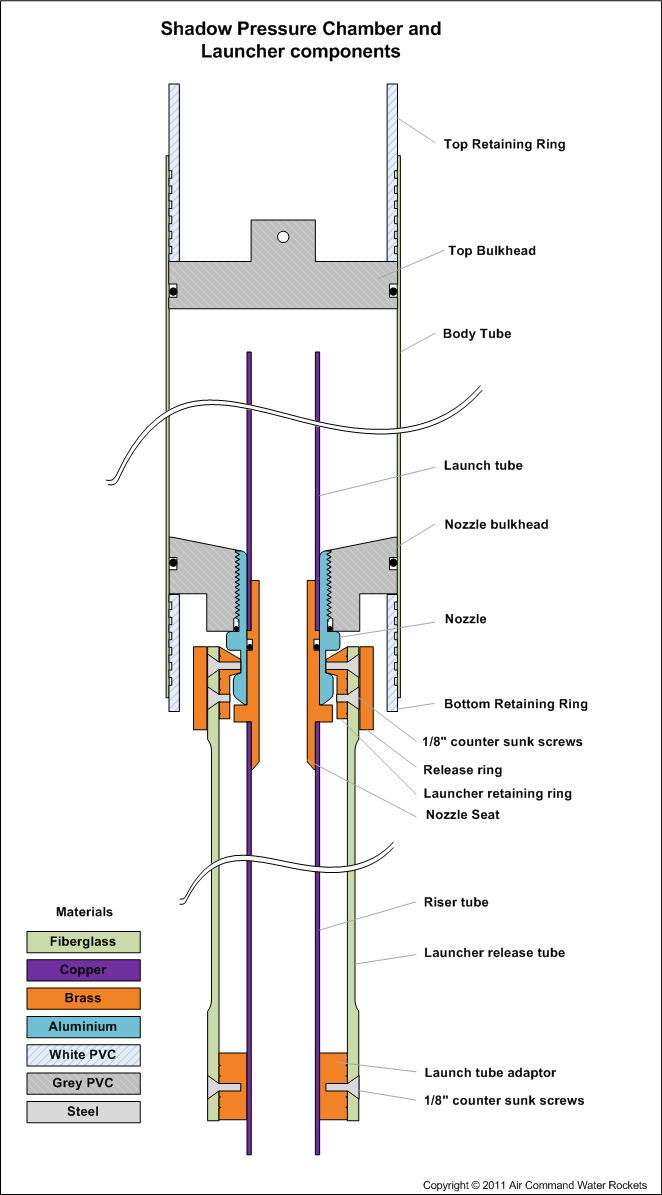
Assembly Drawing - how it all
fits together
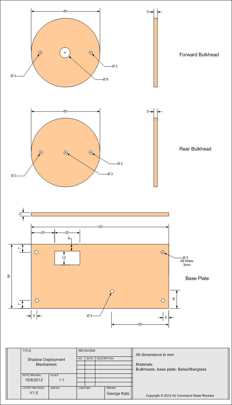
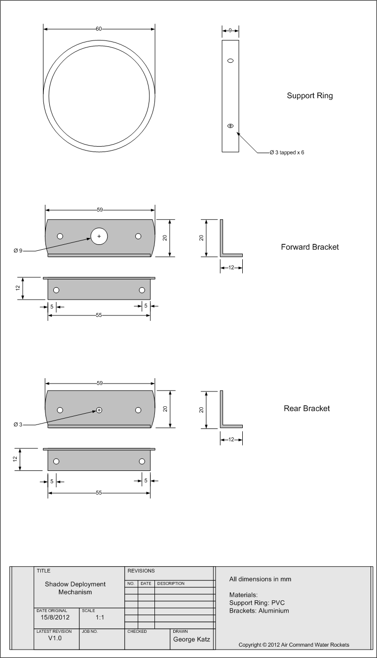
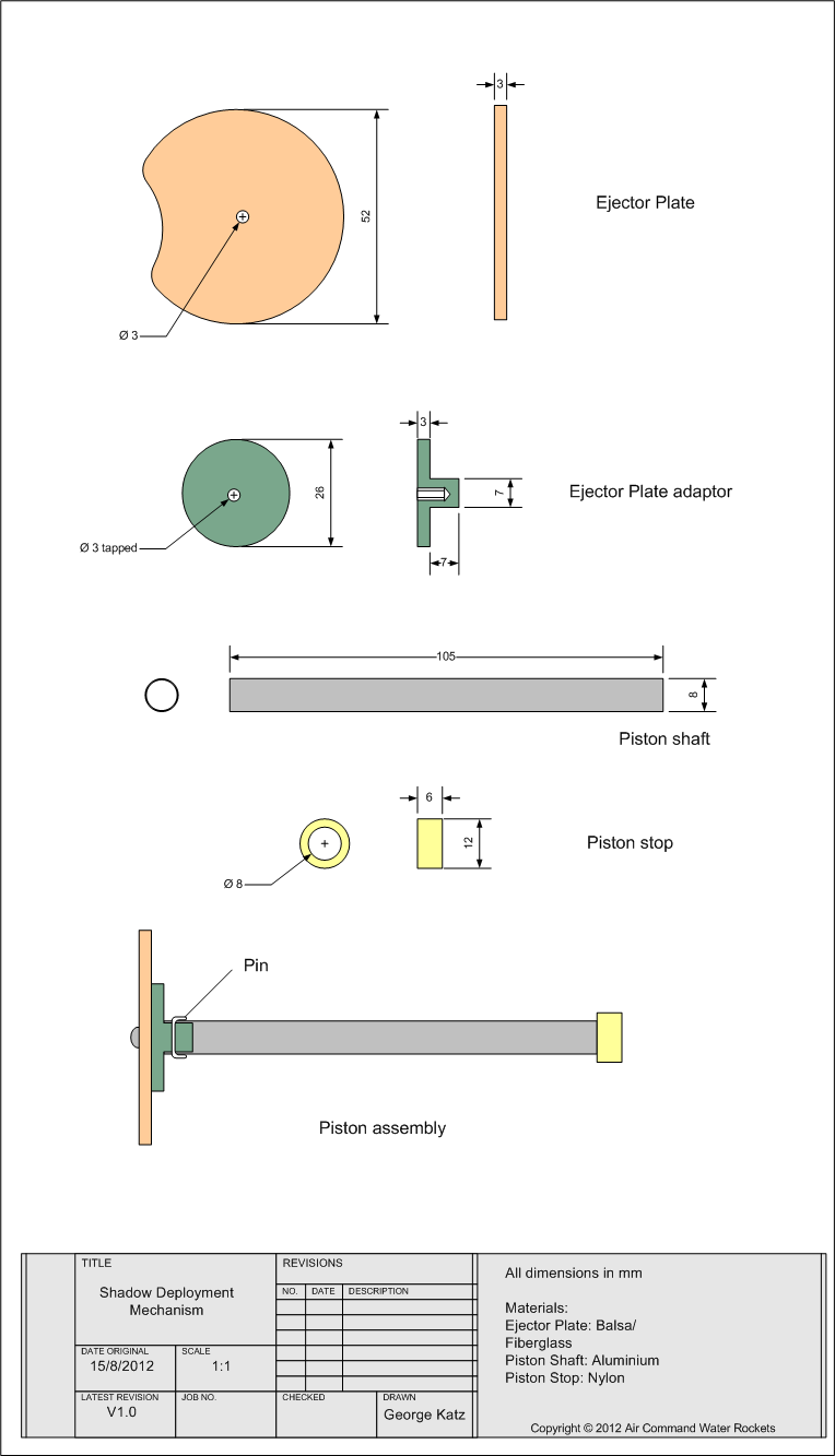
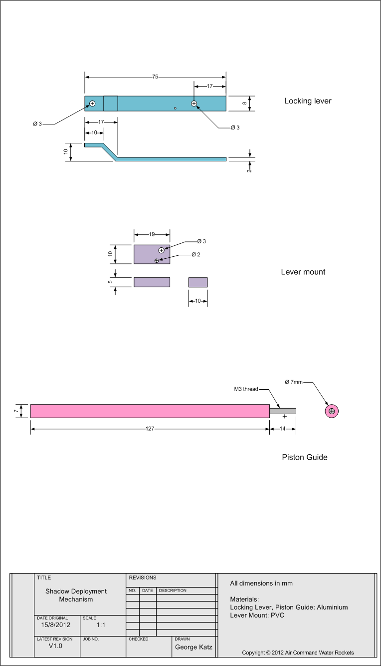
Bulkheads and base plate
Support
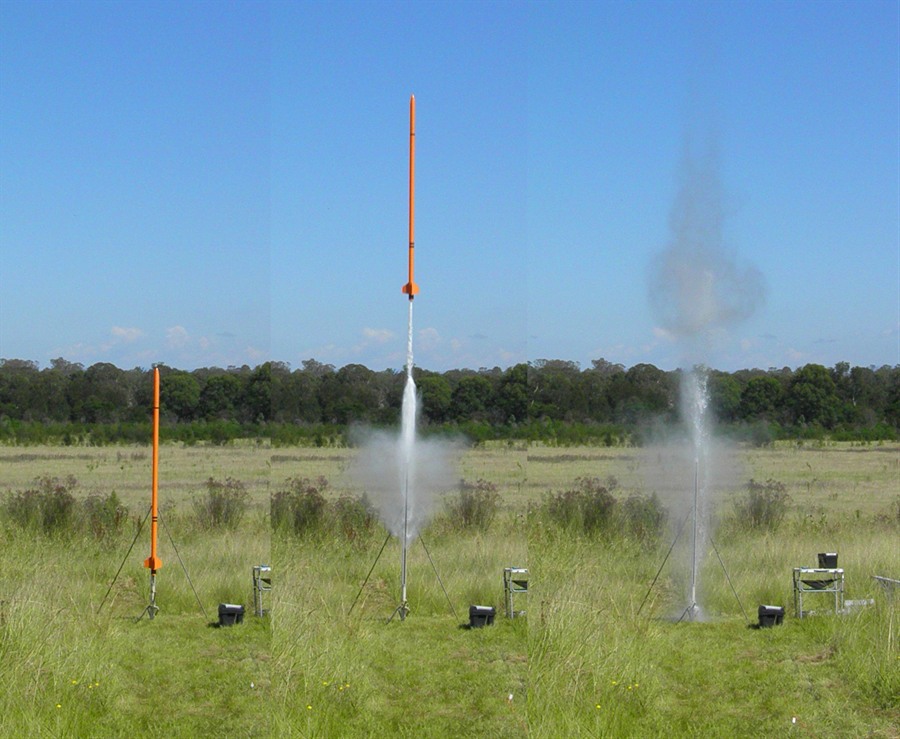
12 February 2012 - First Test
Flights! The full flight report is here:
Day 115
With repairs necessary to the rocket, we
have started a new build log page as this one
is getting too long. Here is the
Shadow II
build log