This build log is in chronological
order so to see the most recent post you
need to Jump To The Bottom.
You may need to refresh this page to see any
latest updates.
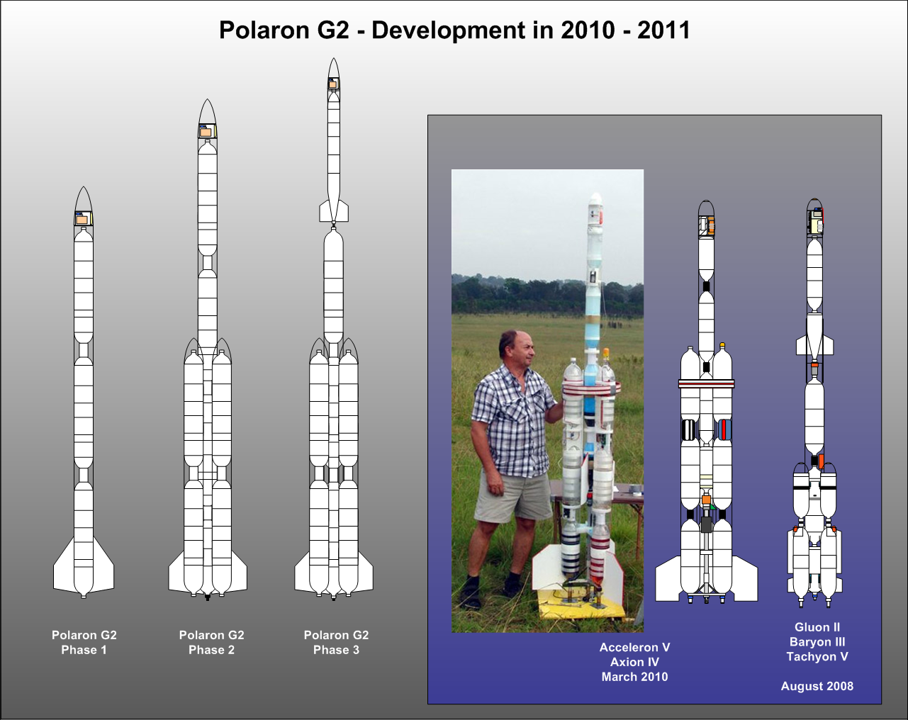
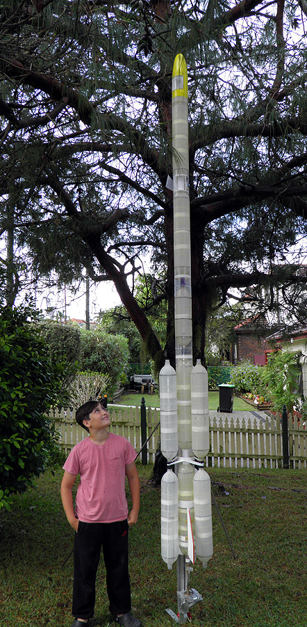
The Polaron G2
rocket will be developed in three
separate phases. We are targeting initial
launch pressures of 250psi (17 bar) and so
most of the equipment will need to be
re-tested/upgraded for these pressures.
Phase 1
The first phase will consist of a 15.9L
single stage rocket. This will use a bigger
nozzle most likely 15 or 16mm. Phase 1 will
test both the rocket systems and ground
equipment to the higher pressures and loads.
Phase 2
In the second phase we will add 3 x
10.6L drop away boosters and extend the
main stage by another 3.15L for a total of
~19L. The nozzle will be reduced for the
main stage to perhaps 9 or even 7mm for a
long sustained burn. Jet foaming will be
used to power the main stage while the
boosters will use larger nozzles and water
only.
This phase will include a set of static
ground thrust tests to measure the thrust
produced by the jet foaming main stage with
different nozzles, to determine which one
will be used in combination with the
boosters.
Together the three boosters will have
slightly more capacity than the Acceleron V
booster.
Phase 3
Phase 3 will be broken into two
sub-phases.
Phase 3a - A small
streamlined sustainer will be developed and
tested. The capacity and size of the
sustainer is still yet to be determined.
Phase 3b - The sustainer
will be fitted to the Polaron G2 main stage.
The main stage will be reduced in length and
capacity to accommodate the sustainer. The
main stage nozzle will be increased again
and the main stage will retain the 3 drop away
boosters.
CAUTION: If you are going to
attempt to build rockets such as these,
please exercise extreme care when testing
and flying them. This rocket uses high
pressures that can potentially cause severe
injury to yourself and those around you.
Always double check your equipment and
review safety procedures before every test
and flight. See more information on
Safety Guidelines.
Build Log
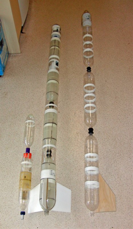
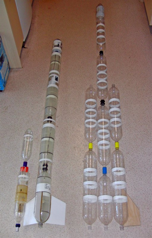
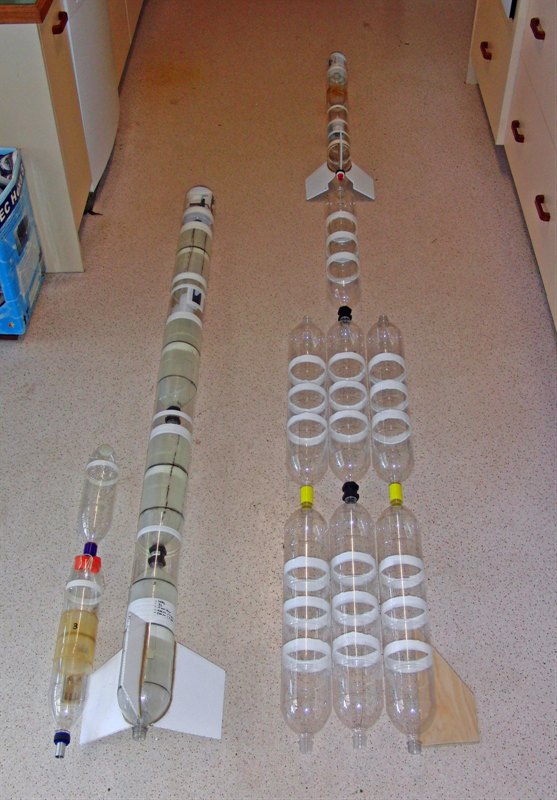
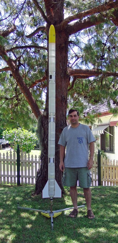
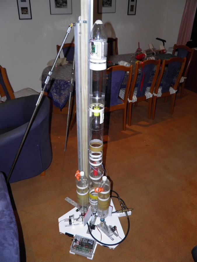
25 September 2010
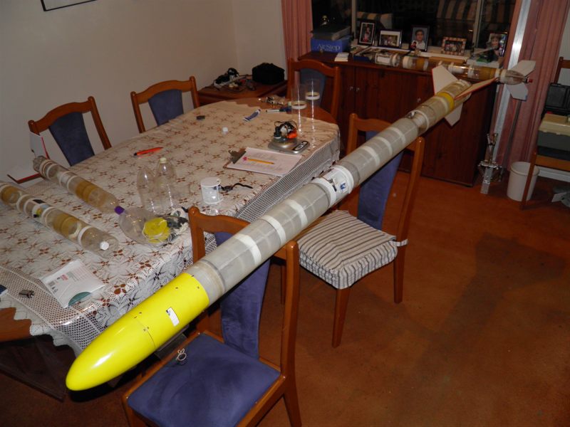
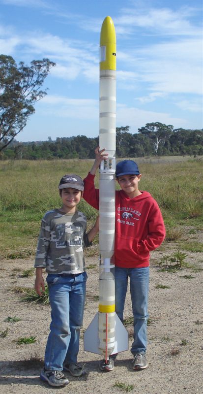
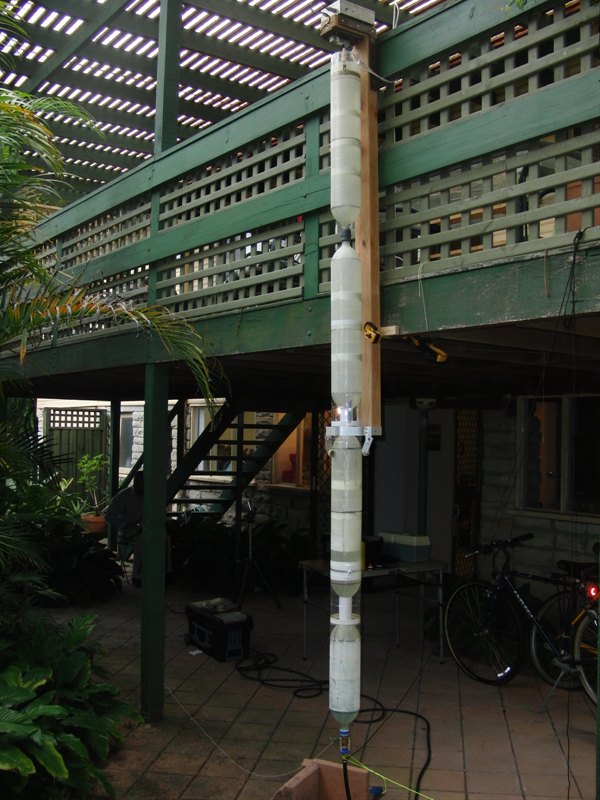
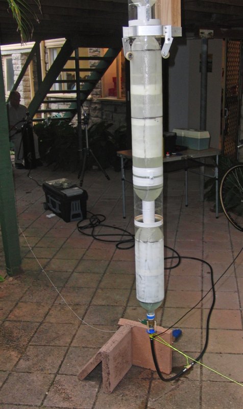
- Start of project - See
Day 96 for more details and photos. We
laid out the rocket on the floor to get an
idea of the size of the final rocket. It's
going to be fairly large and so we'll need
to consider how this will be assembled at
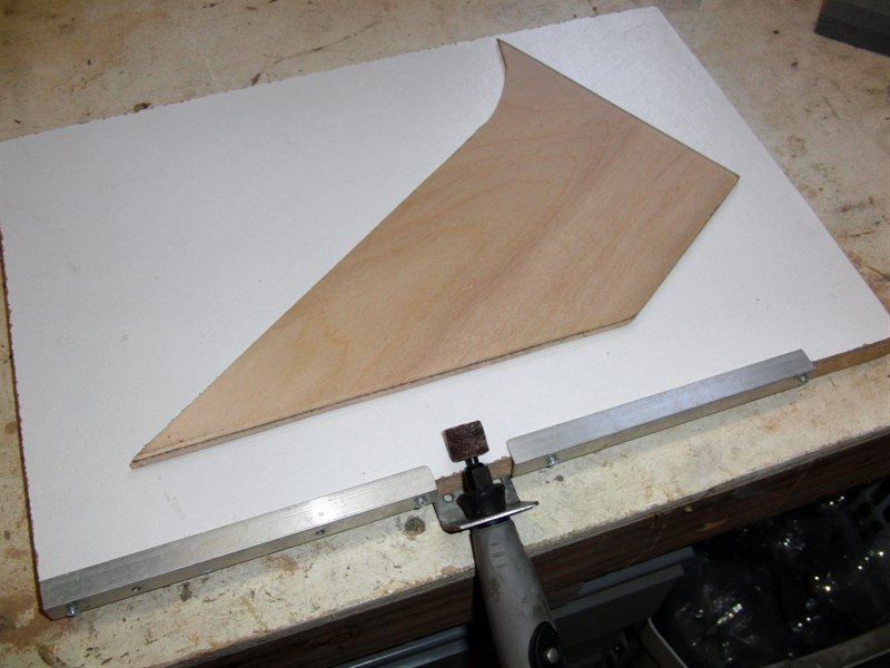
the launch site. We
also made a fin bevelling jig to give
plywood fins a nice even edge.
phase 1
phase 2
Phase 3
Bevelling the edge of a fin on
the bevelling
jig.
30 October 2010
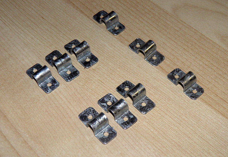
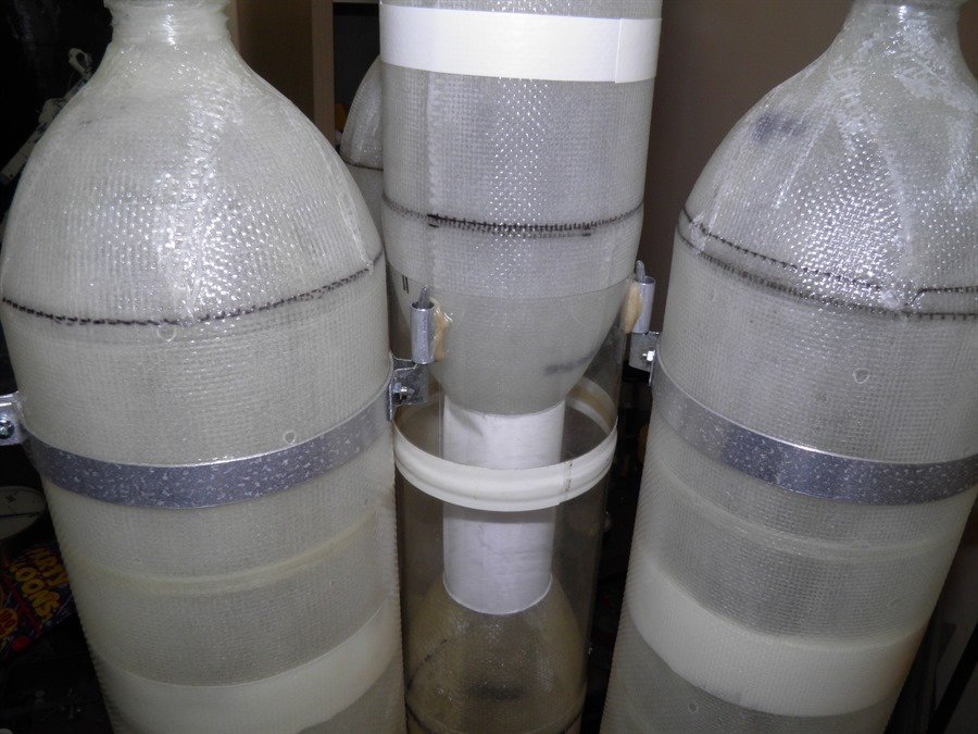
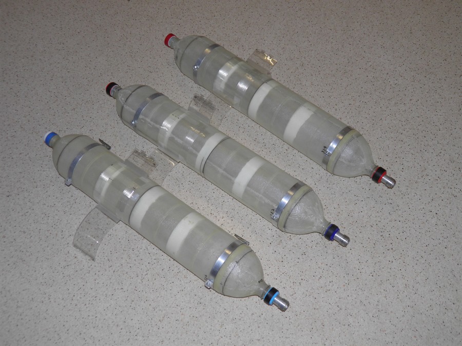
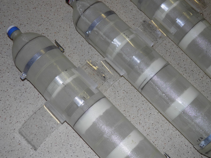
- We started creating the reinforced spliced quads.
These are reinforced with 200gsm glass
cloth. We also pressure tested them to
270psi. See Day
97 for details.
Wrapping glass fibers
into
grooves
We use West Systems
epoxy as the resin
Spliced quads
ready for
assembly.
Phase 3 main stage
assembled with a
representative sustainer on top.
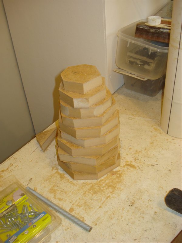
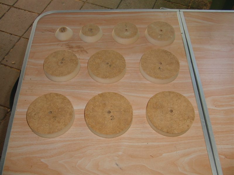
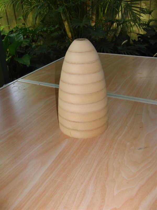
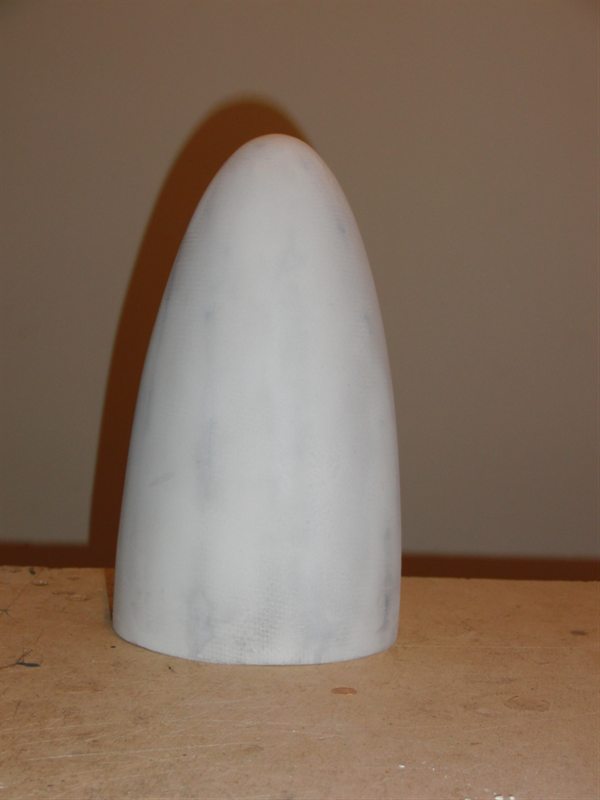
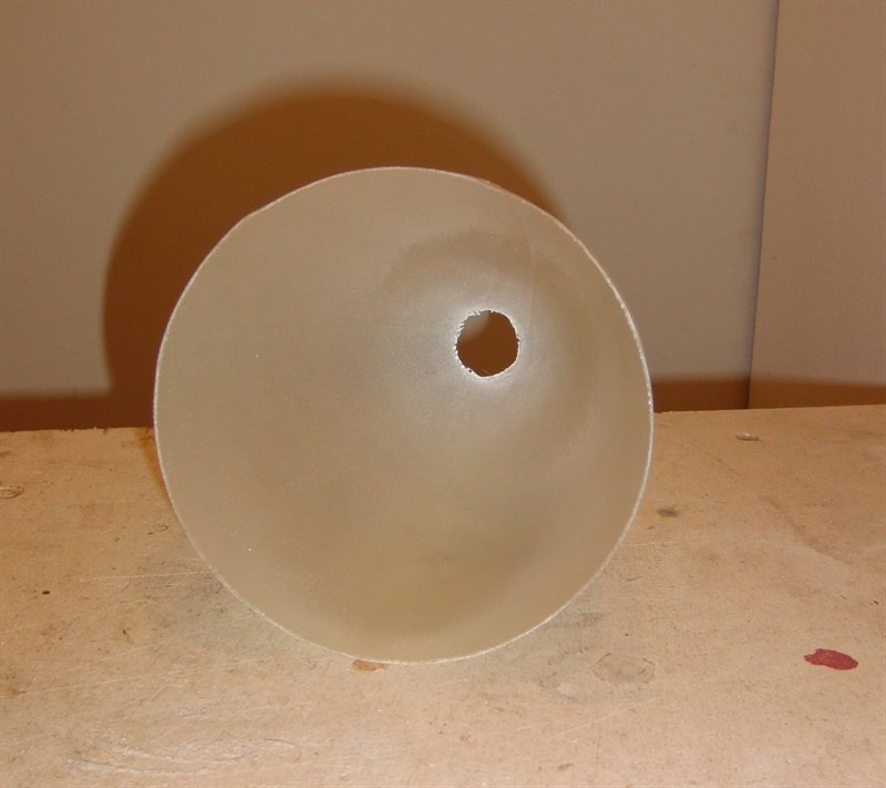
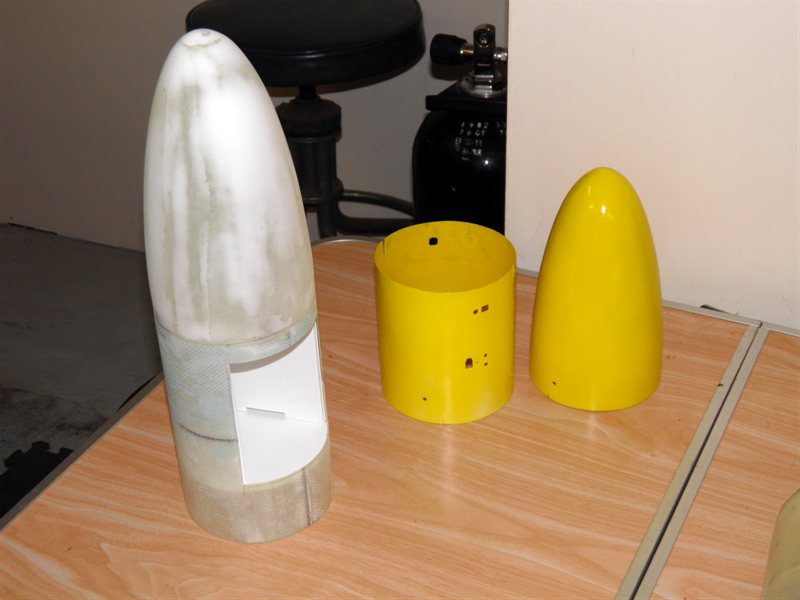
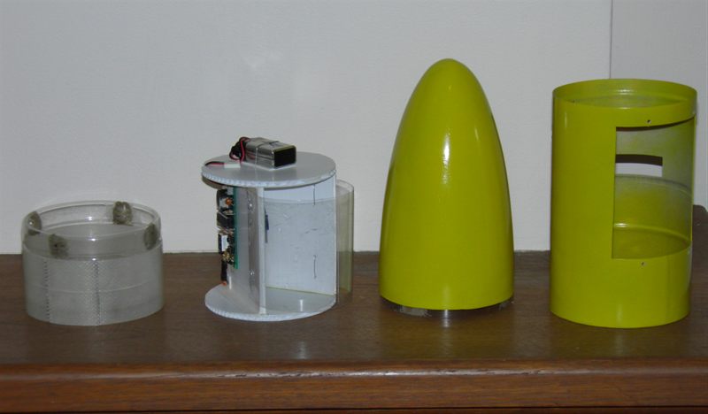
We also made the nosecone plug out of MDF rings
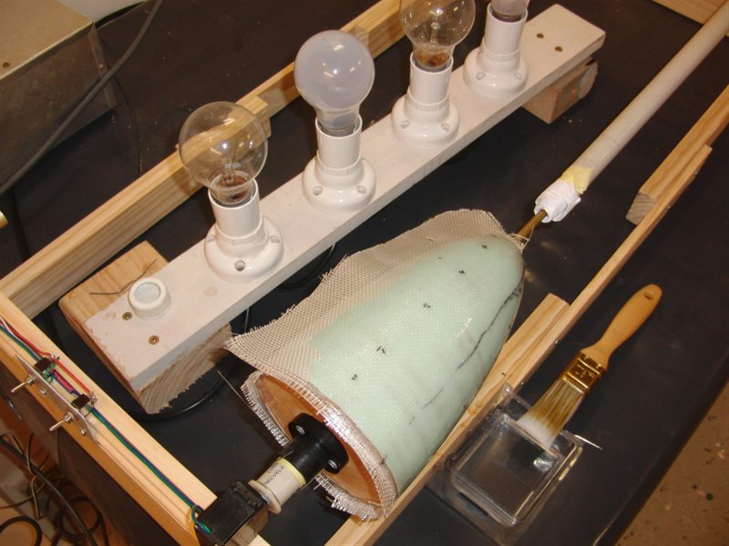
and glued it together. We had our
first go at fiberglassing using the plug
with mold release. This didn't work out too
well and we had to cut the nosecone away
from the mold.
Rough cut MDF
Machined to size
Assembled
First nosecone
layup
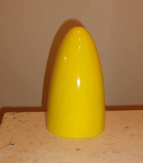
Filled and sanded
Final nosecone
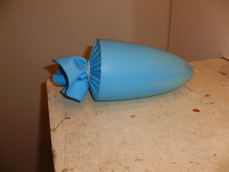
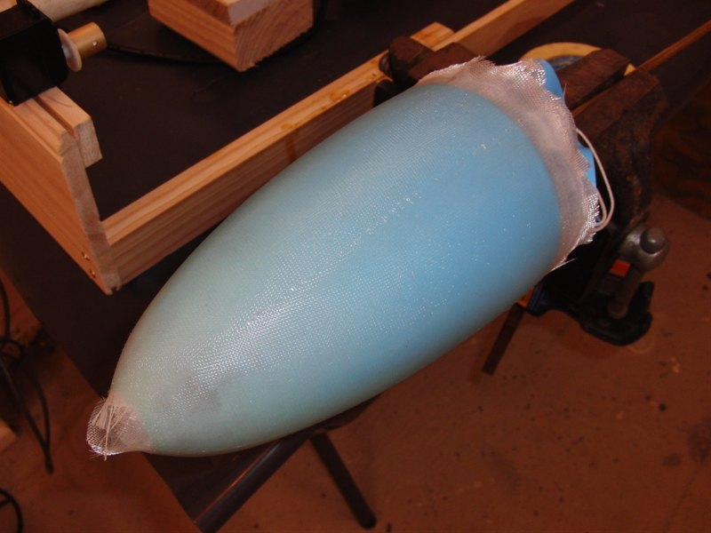
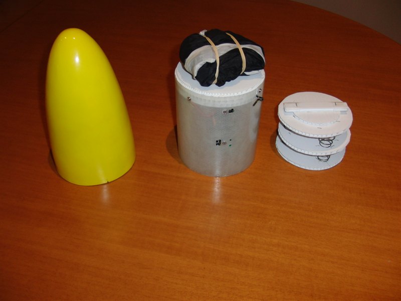
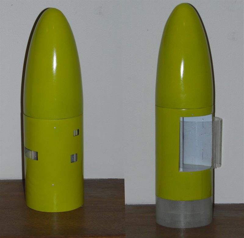
27 November 2010 - Second attempt
at a nosecone, but this time using a
swimming cap as the mold release. See
Day 98 for details.
Swimming cap wrapped
on plug
Adding layers of glass
Came away cleanly
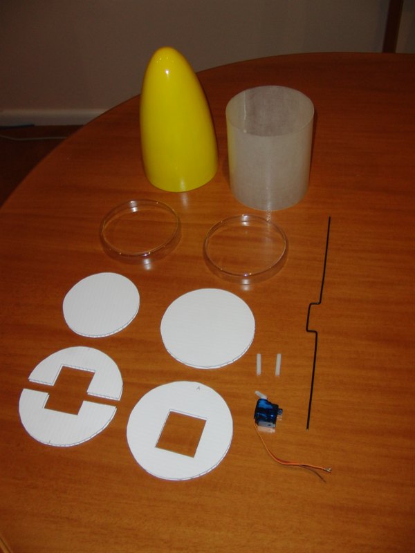
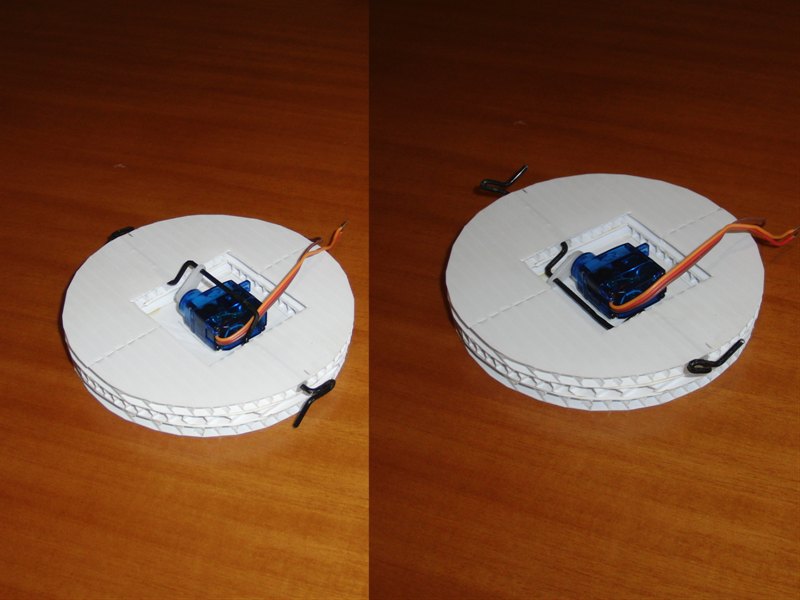
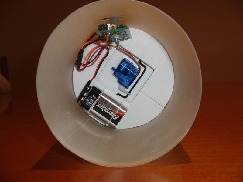
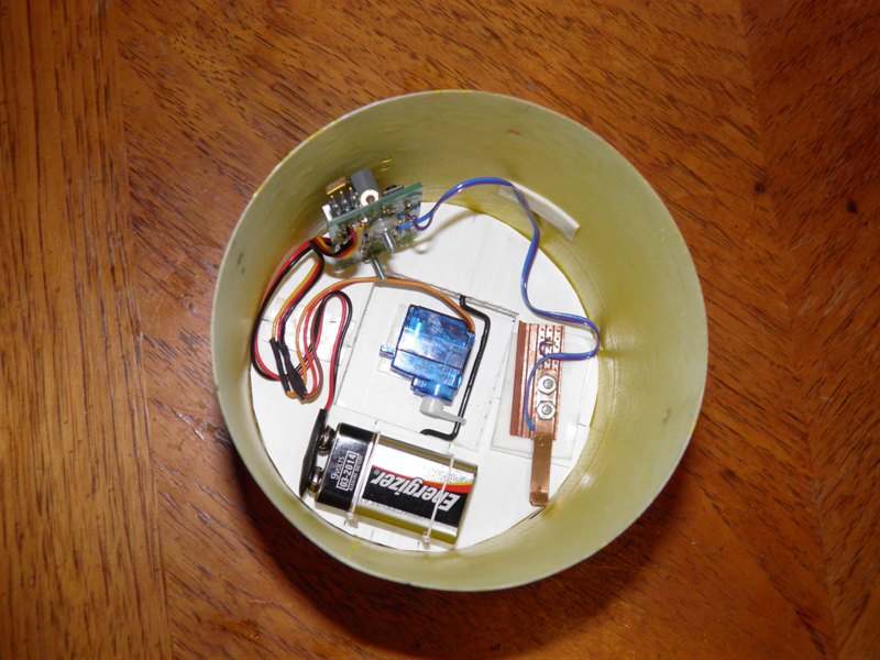
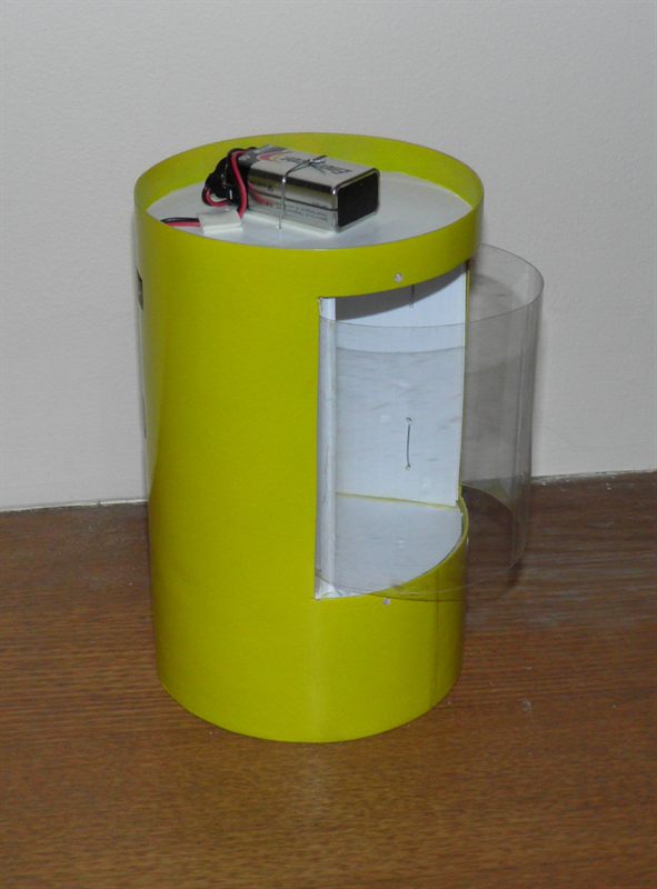
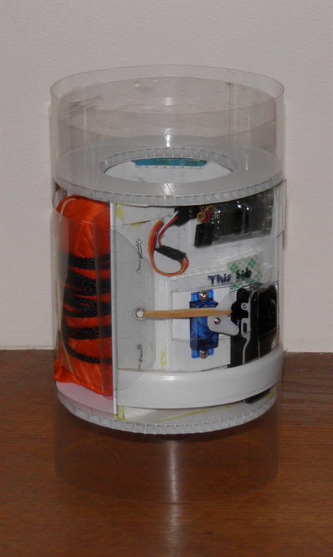
We also made the deployment mechanism.
This was designed to be an inline mechanism
with the nose being pushed off. A servo
motor releases the nosecone by releasing a
couple of rubber bands.
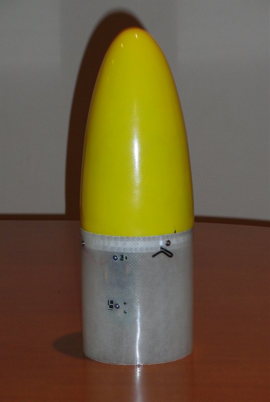
22 January 2011 - Today we tested
the nosecone deployment mechanism on a small
rocket. See Day 99
for more information about this launch.
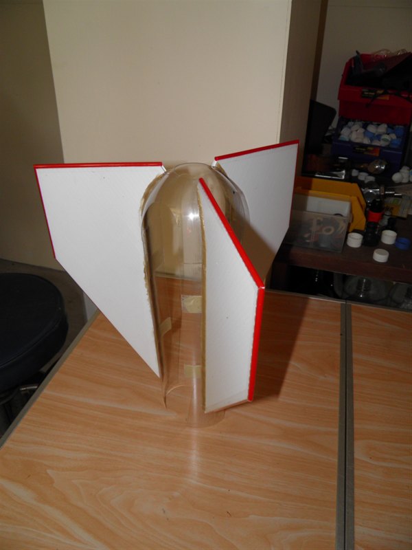
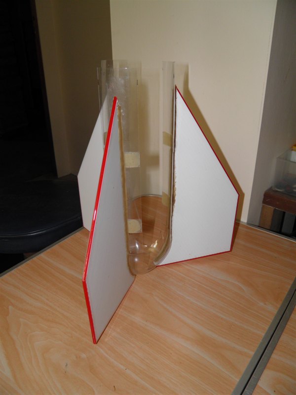
We also made the fin can for the G2
from 5mm Corriflute. We added drinking
straws to the edges for better
aerodynamics.
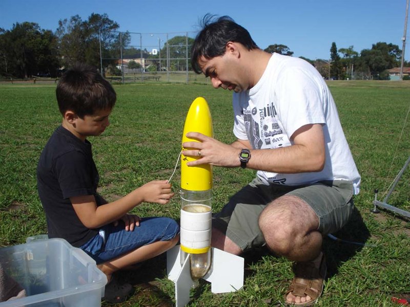
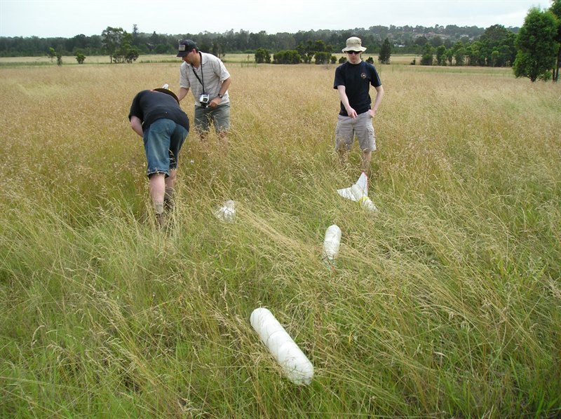
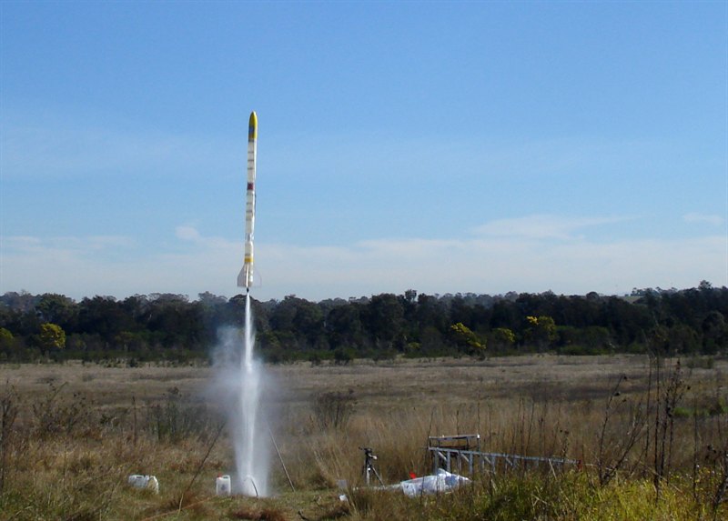
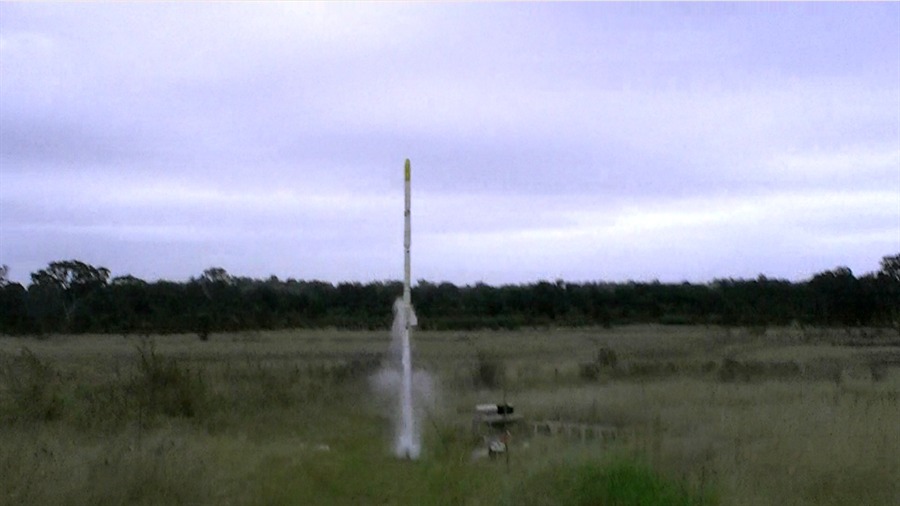
29 January 2011 - First launch of
the Polaron G2 rocket. See
Day 100 for launch
details including video. Not everything went
according to plan and it looks like the
nosecone deployment mechanism didn't work
out all that well. We'll have to revisit
this.
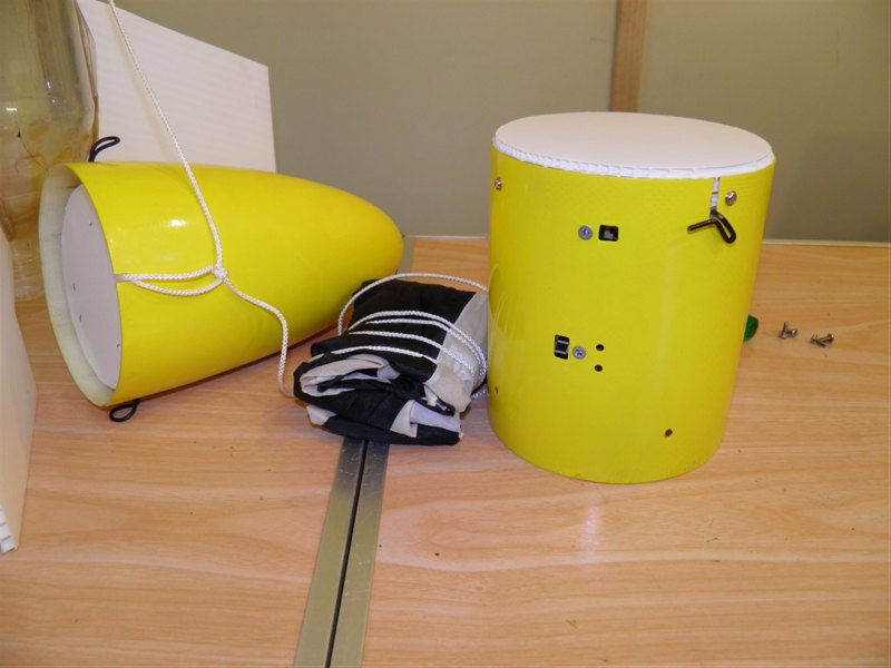
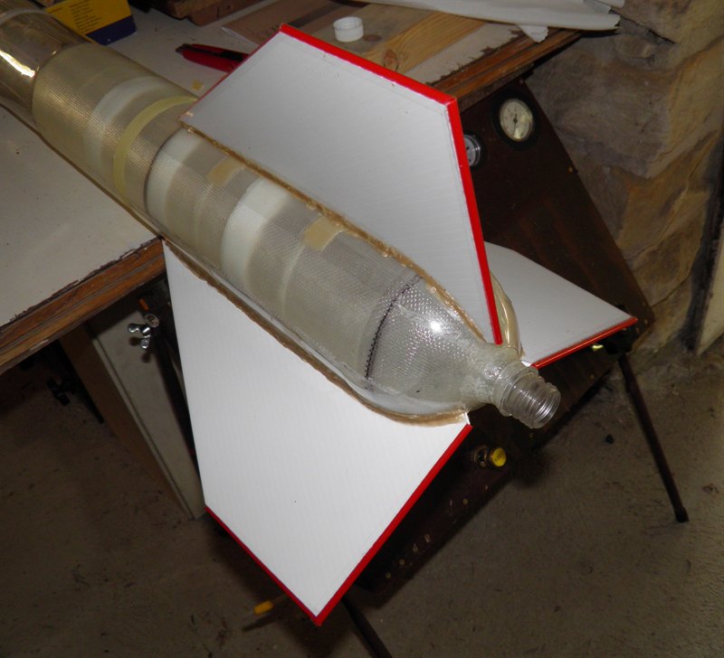
26 February 2011 - Started working
on a new side deploy pod to replace the
deployment mechanism. See
Day 101.
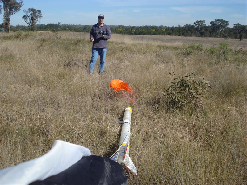
10 April 2011 -
Having repaired the nosecone we also built a
backup parachute system that was mounted
half way up the rocket. This uses a uMAD to
detect apogee so it can deploy the
parachute anytime the rocket tips over. See Day 103
for more details.
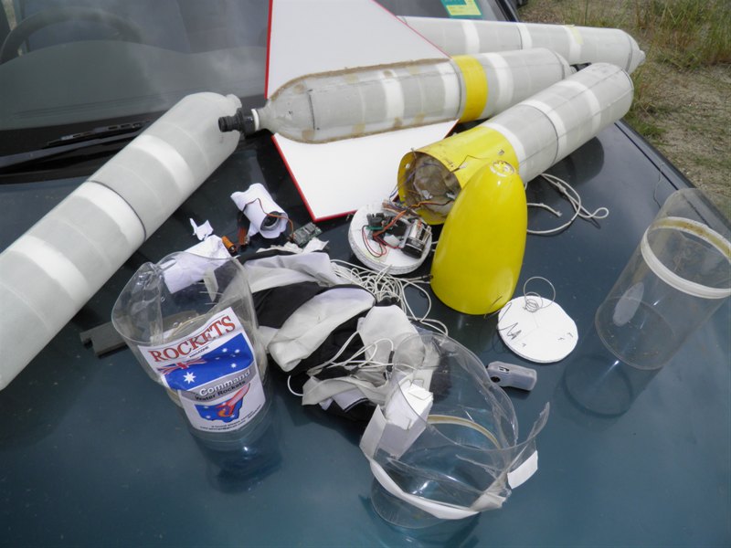
A spectacular CATO failure of
the Polaron G2 today that not only
damaged the rocket but also the
launcher.
Backup
parachute pod
uMAD and STII
T -5 minutes
That will buff out.
22 April 2011 -
We did some thermal pressure tests to try to
identify why one of the spliced quads would
have exploded. See Day 104
for more details about the thermal
tests. We also repaired the nosecone and the
backup parachute system.
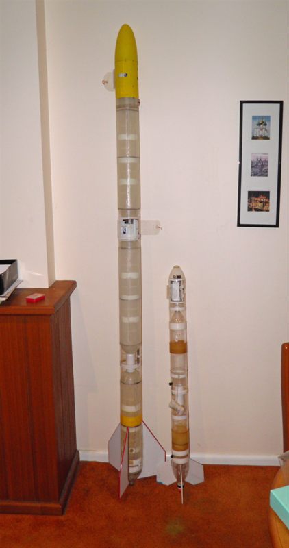
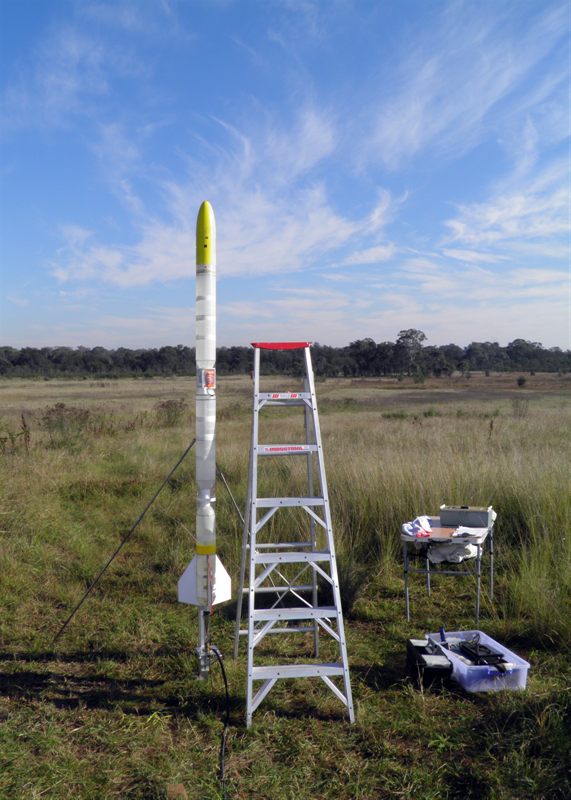
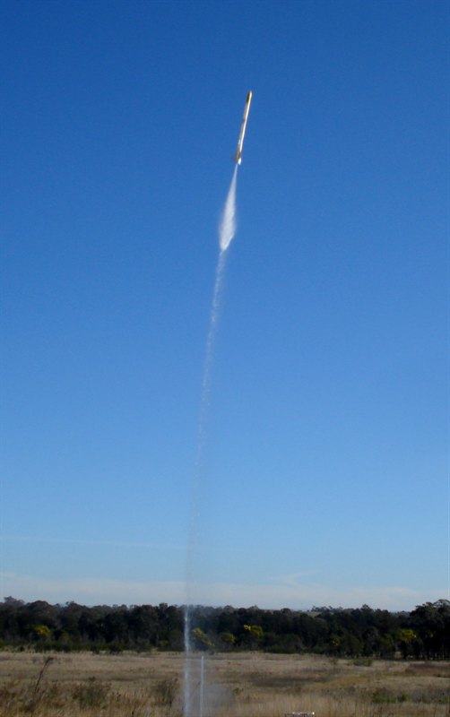
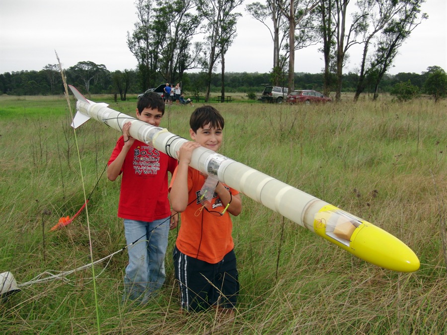
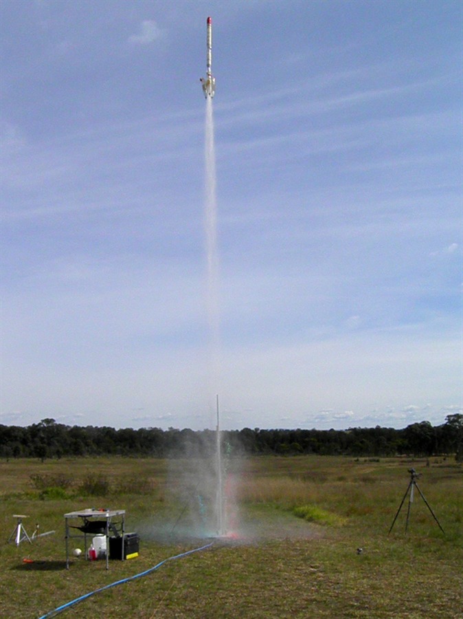
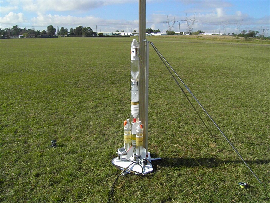
8 May 2011 -
Successful launch day for Polaron G2b. The
G2b is a spliced-quad shorter than the full
G2. The rocket behaved
itself and performed great. This also
marks the completion of Phase 1 of this
project. See Day 105
for the flight day report.
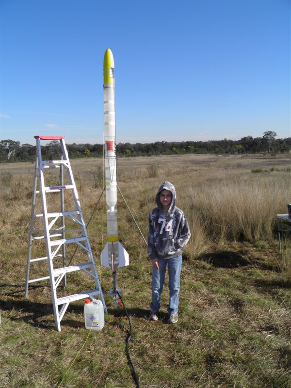
Repaired Polaron G2b being
prepped the night
before.
Little Axion next
to big cousin.
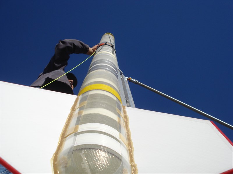
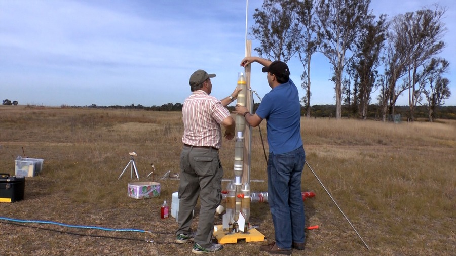
The top section of the rocket
is screwed to
the lower
half already on the pad.
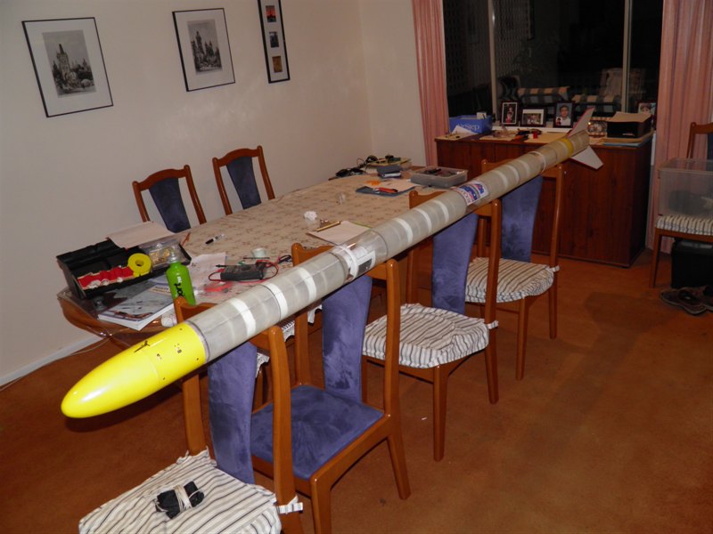
Launched at 210psi.
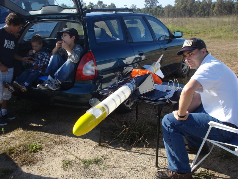
Downloading flight data
We need a bigger table.
A photo for the boys
to take to school for
their weekly "news".
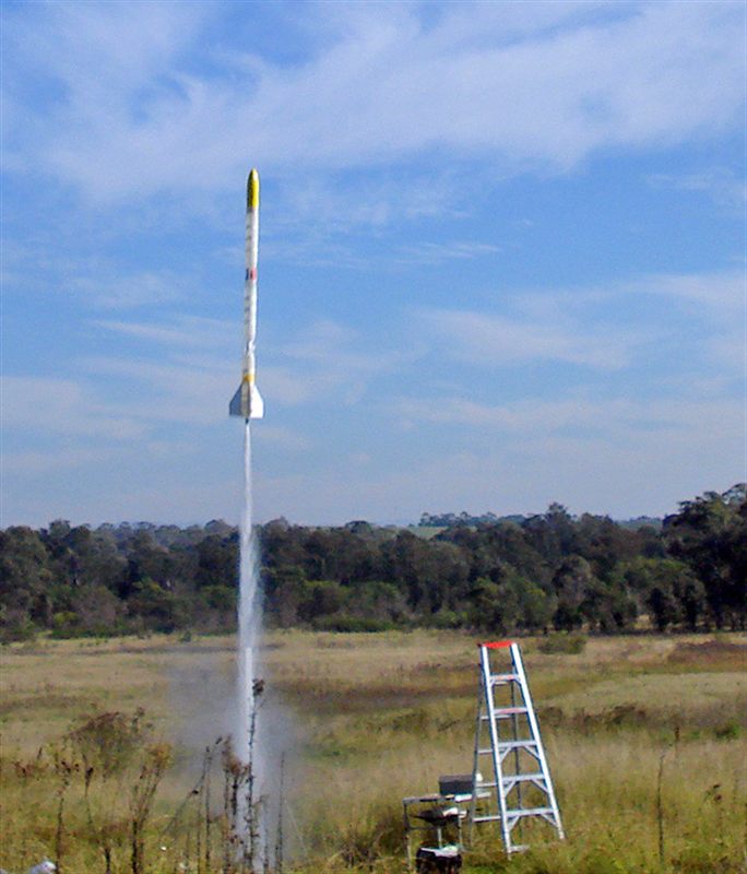
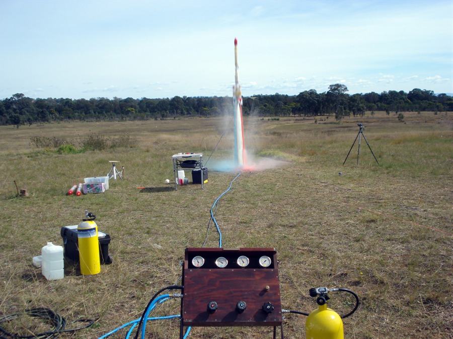
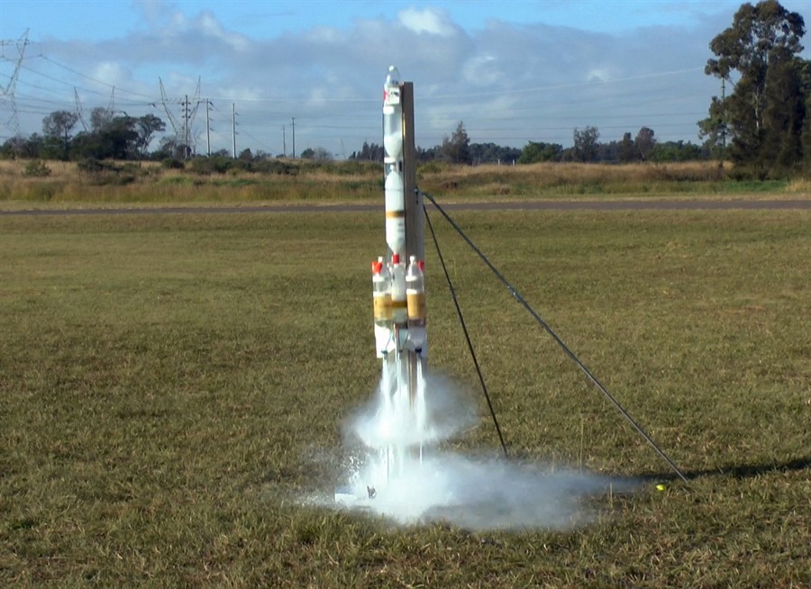
30 July 2011 -
Two more good Polaron G2b flights. See
Day 109 for the
full flight report from the day.
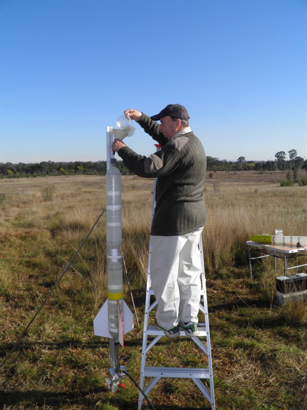
The rocket uses
3.8L of water.
Arming electronics.
Launched at 230psi.
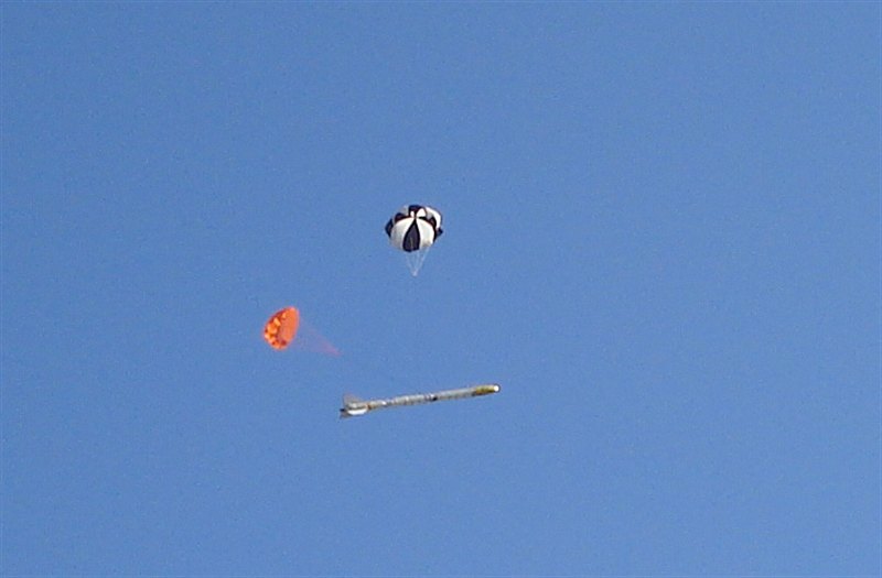
Both main and backup
parachutes opened just
after apogee.
Launch crew doing
final inspections.
Second launch at 240psi.
Hurray ... no need for
repairs today.
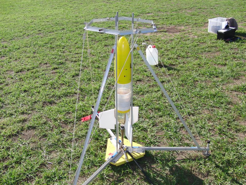
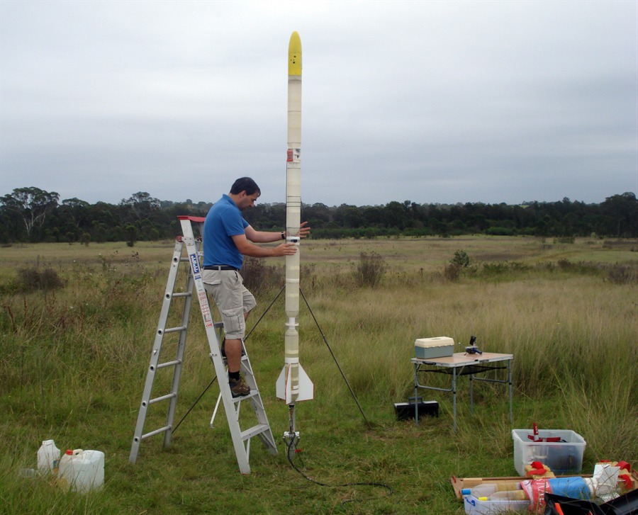
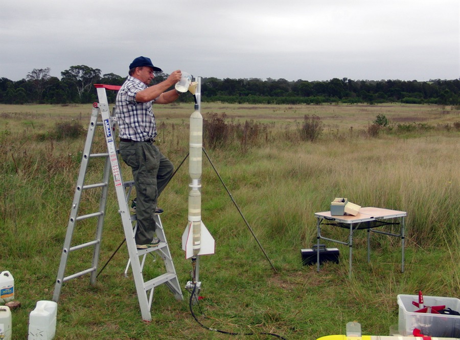
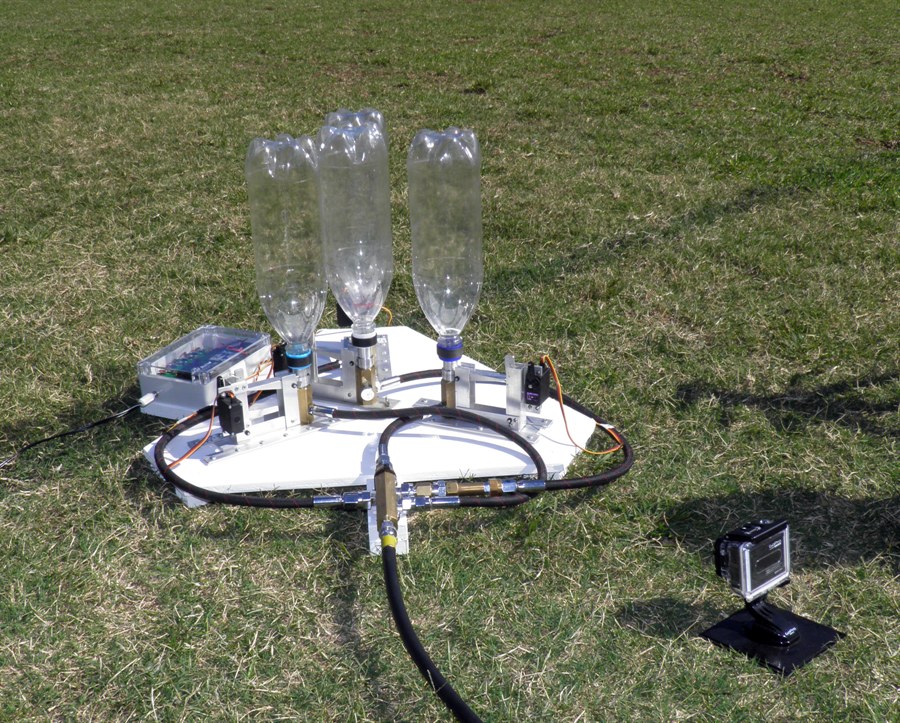
7 August 2011 -
We did a full scale test of the Polaron G2
Phase 2 rocket on the test stand. We wanted
to get an idea of what the overall thrust
will be as well as the burn duration. With
the 9mm nozzle the burn times were nice and
long. I think it will be quite spectacular
to see this long burn in action. See
Day 110 for more.
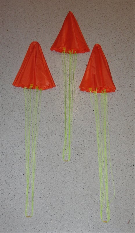
We also made the booster parachutes that
should bring them back down safely.
The G2 main stage is
attached to the test stand.
The yellow string stops the rocket
swinging
sideways during release.
The black string stops
the release
head from hitting the ground.
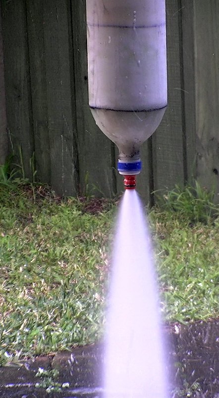
9mm nozzle under test.
Finished parachutes.
8 April 2012 -
Launching the full size Polaron G2 at 220psi. See
Day 118 for full
flight report.
Top section is screwed on.
Filling with 4 liters of water.
Launched at 220psi.
Having faced high acceleration
and landing
the rocket now
must deal with the eager recovery crew.
14 August 2013
- After a pause
in development we have started this project up again. As an
interim step we are going to try launching a
smaller reinforced rocket first with smaller
boosters. The purpose of this test will be
to test new booster attachment mechanisms
that should be able to hold the boosters at
the higher pressures. We are going to be
using the Axion G4 rocket which has flown a
number of times. If the tests go well we'll
apply the same modifications to the Polaron
G2 rocket.
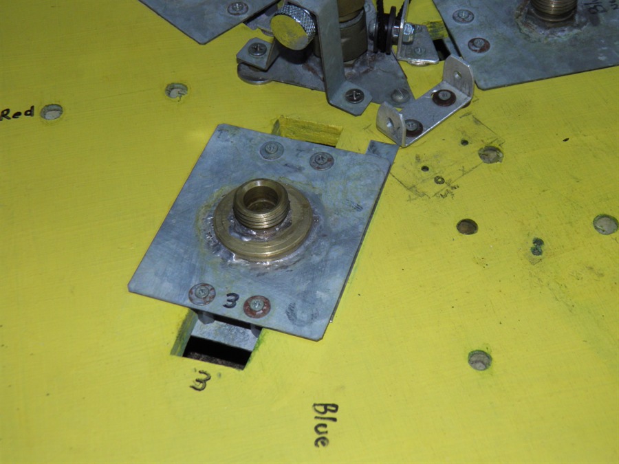
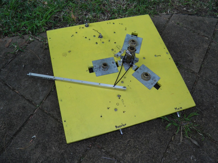
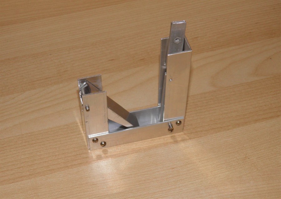
20 August 2013
- In order to continue development
of the rocket, we needed to make a couple of
fixes to the launcher. Unfortunately a box
fell on it a few months ago and damaged one
of the nozzle seat mounts. We repaired the launcher
today and machined up a stronger mount that
was then soldered to the nozzle seat and the
sliding plate. We've done this to two of the
seats so far, and when the last one breaks
we will do it to that one as well.
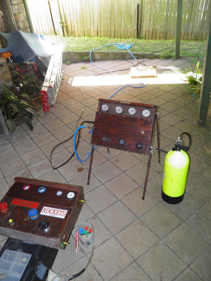
We also added a new longer lever to the
launcher to make it easier to release the
rocket at higher pressures. The control
panel was also tested and a couple of
o-rings replaced that were looking a little
worn.
Newly soldered nozzle seat mount
Booster fill tubes fitted to
launcher.
Attached a longer release arm.
Testing end to end connections
between panel and launcher.
The intention with the smaller rocket is
to launch the rocket at higher pressure
(200psi) while still using lower pressure
(120psi) for the boosters. Our control panel
has the dual pressure capability so we are
going to use it. We are also going to fly
the main stage with a 7mm nozzle to stretch
the thrust out even more. The 7mm nozzle
isn't enough to launch the rocket
by itself and so the boosters should get it
up to reasonable speed. This is more or less
a scale test of when the Polaron G2 is
launched with a 9mm nozzle.
We already have a brass 7mm nozzle so we
are going to use it on the main stage.
22 August 2013
- One of the first
things that needs sorting out is how to hold
onto the boosters securely especially when
using higher pressures and bigger nozzles.
The glued on pins and tubes we used on the Polaron series just aren't going to cut it.
Each booster will exert a force of
approximately 600N (61kgf) on the attachment
point. That's a total of 1800N (184kgf)
pushing on the central stage. Add a safety
margin to it and you are looking at over
2000N (200kgf) That's a couple of larger
adults hanging off it!
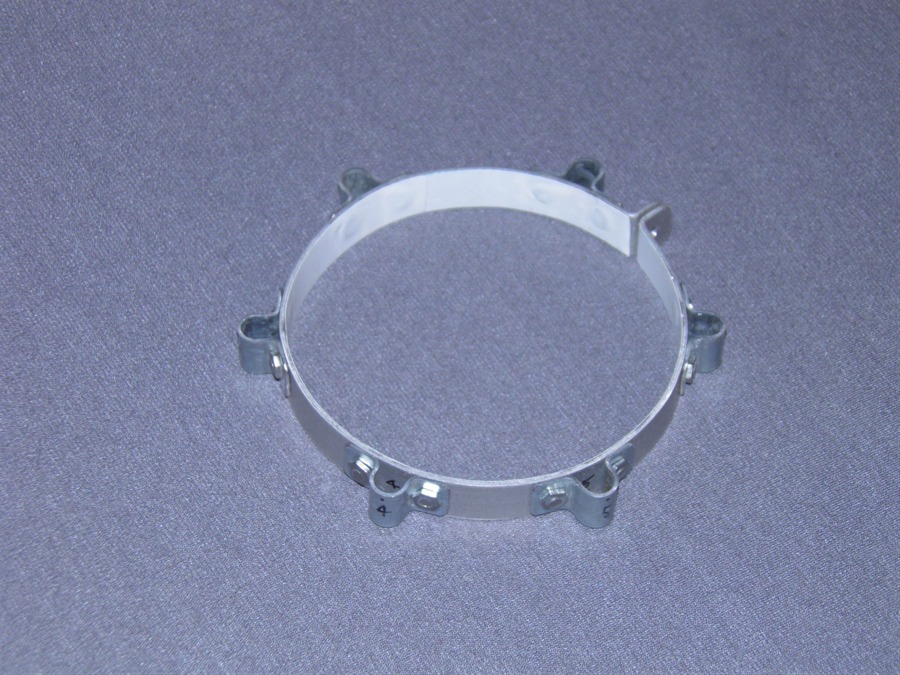
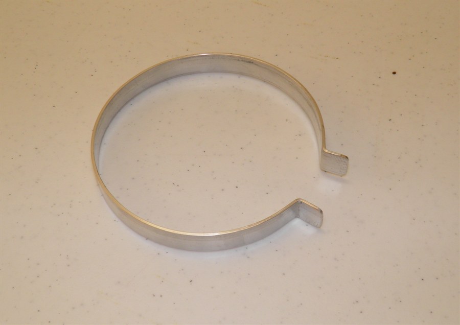
The fixed tubes had a couple of
disadvantages in the design flexibility. So
the solution we are testing is a clamp that
sits against a thrust ring attached to the
outside of the rocket. Some advantages of
the clamp approach include:
We can detach it and move it between
rockets.
We can adjust the positions of the
individual loops to fine tune where the
booster sits
We can attach a rail button to it
It can clamp the fin-can under it.
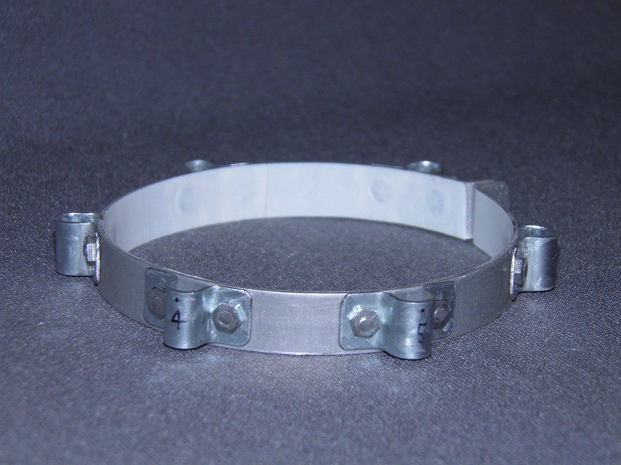
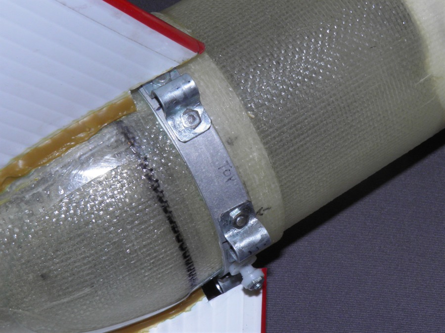
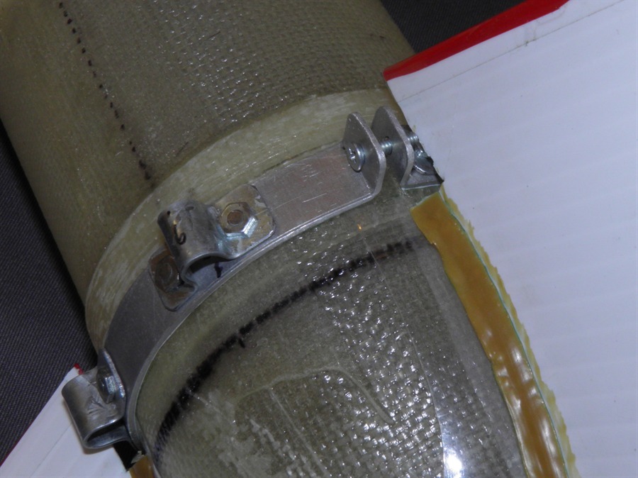
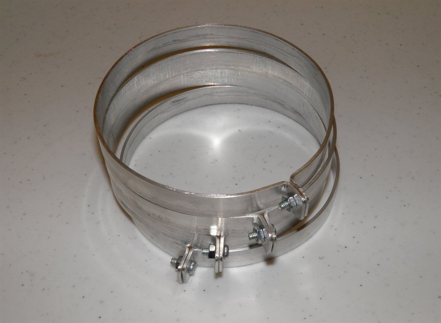
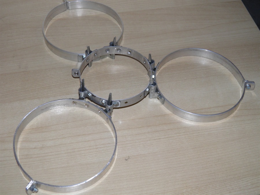
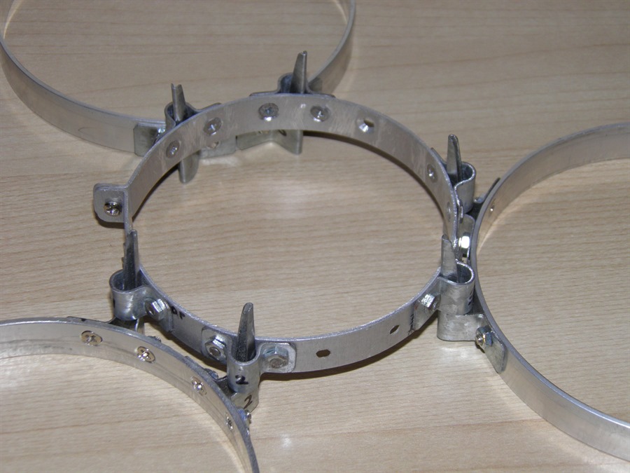
We made the clamp today to fit a 90mm fiberglass reinforced
airframe. The ring is made from aluminium to
reduce weight, but the loops are made from
steel to stand up to the concentrated forces
without deformation. Each loop was attached
with a pair of 1/8" counter sunk screws. We
then used a Dremmel tool to cut off the
excess thread. The clamp weighs 38 grams. We
put a strip of electrical tape on the inside
to help protect the fiberglass airframe and
provide for better friction.
Fin can is held down by the
clamp
Booster clamp
Detailed view
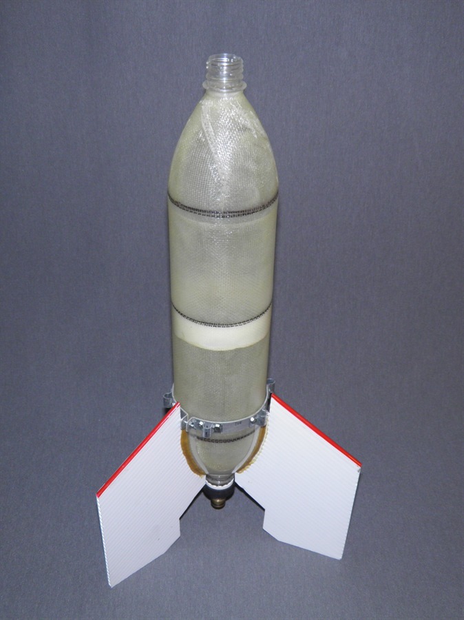
Test fitting clamp with fin can
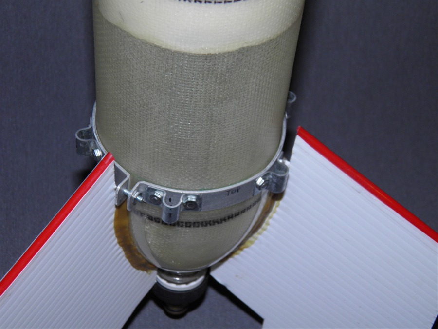
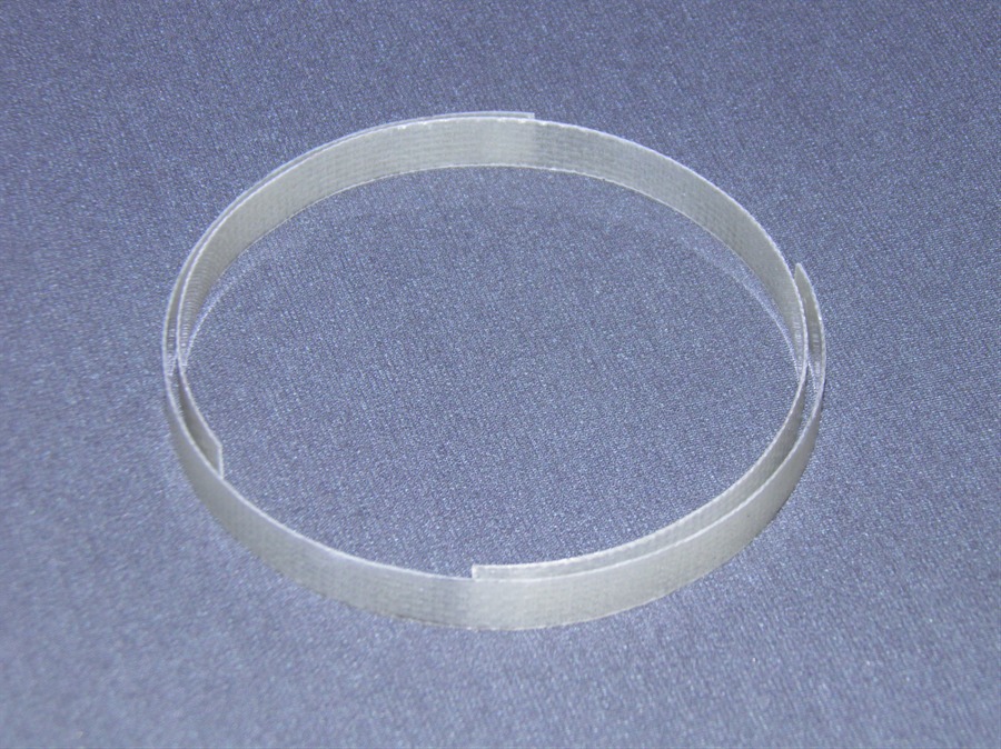
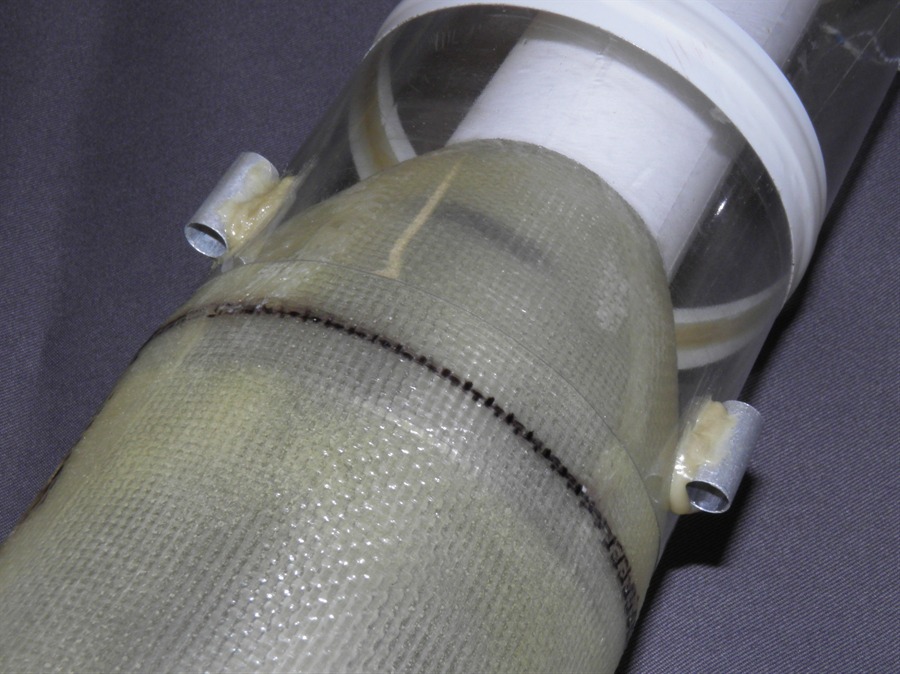
23 August 2013 -
We made the thrust ring today. The thrust ring is
made from a pair of fiberglass rings cut out
from an old 110mm reinforced splice. The
ring is 12mm wide.
Fiberglass thrust ring is made
of two layers
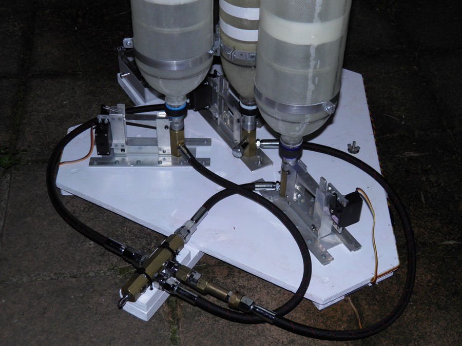
24 August 2013
- We attached the thrust ring to the rocket
body with 24Hr Epoxy. We used rubber bands
to hold the rings closed while the glue
cured. In order to simplify the launch
procedure we decided to set the pressure
regulator at 210psi and we will keep it
there. During the fill we will only use the
individual line valves to pressurise the
rocket and boosters to their specific
pressures and shut them off when the target
pressure is reached. We have to be careful
not to over-pressurise the boosters.
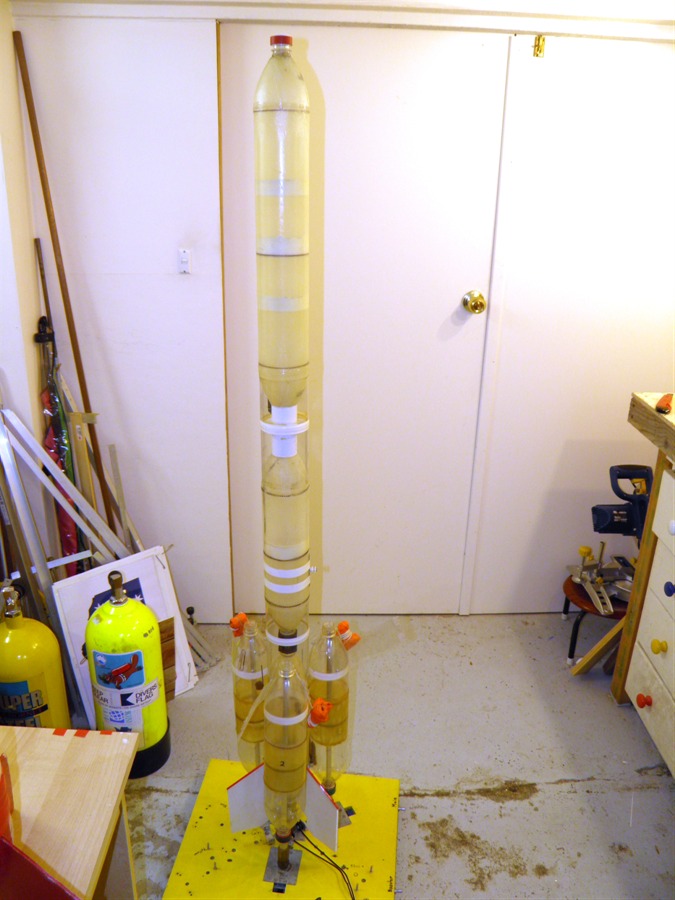
Test fitting the rocket and
boosters
Finding the location of where to
put
the booster clamp and thrust
ring
The rocket was sanded prior to
gluing
Thrust ring glued in place
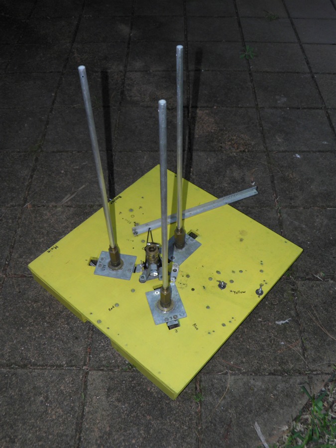
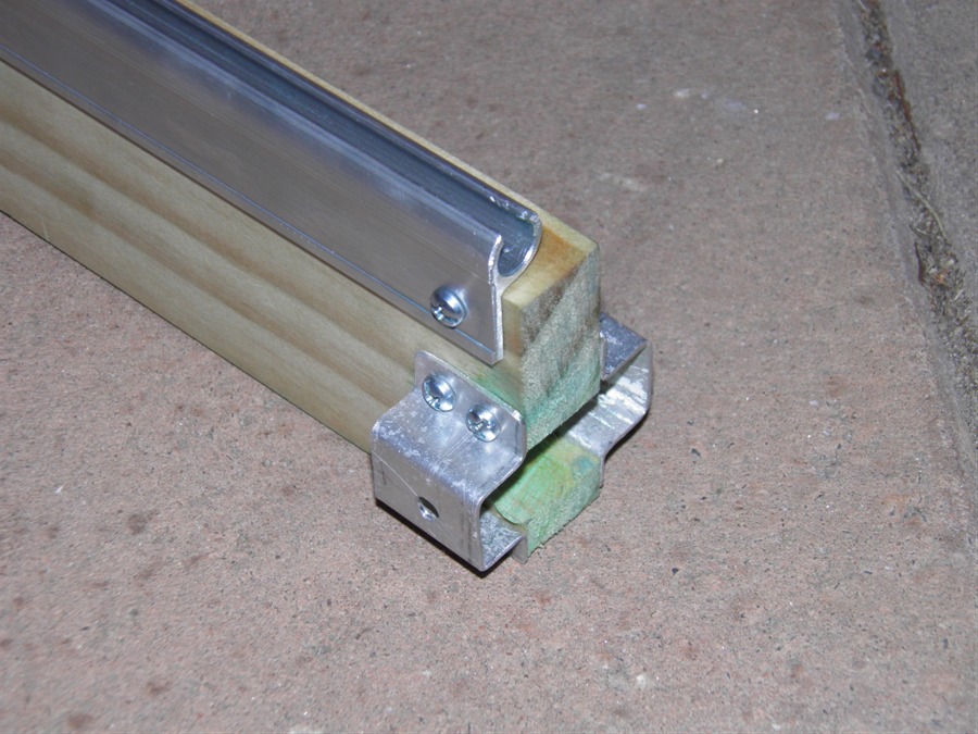
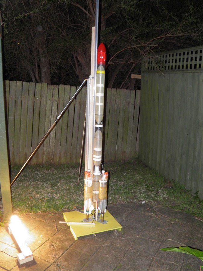
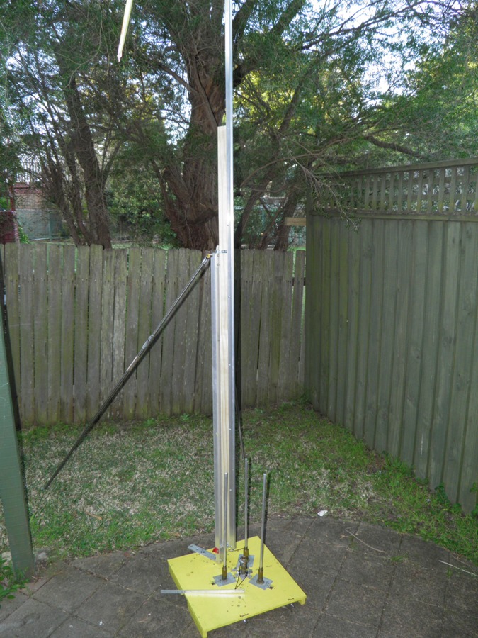
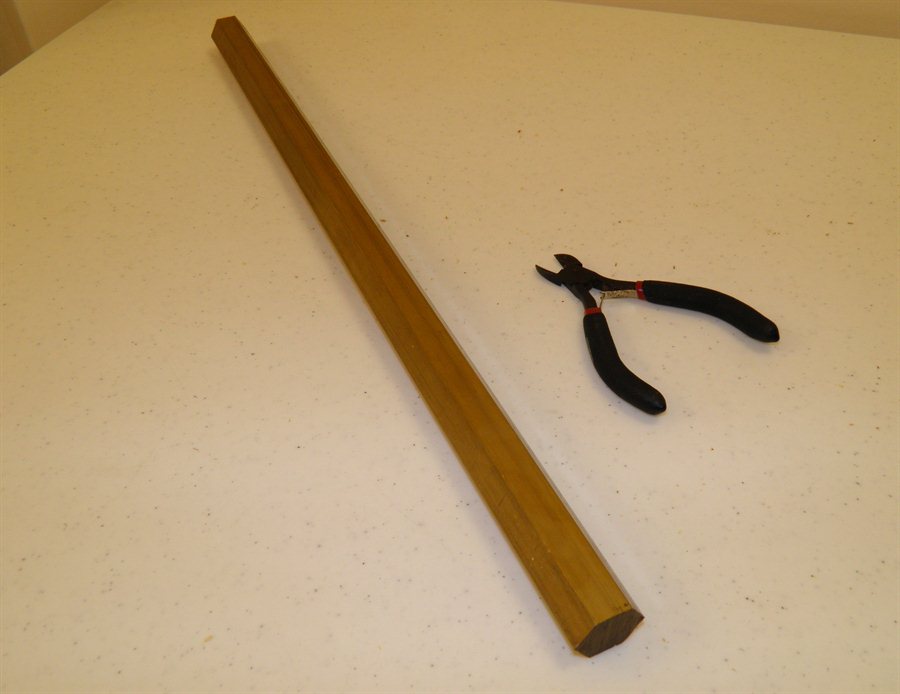
25 August 2013 -
Due to the smaller diameter main stage,
we didn't have enough room to use our normal
guide rail. So we needed to make a narrow
guide rail. We bought a 3m long aluminium
extrusion from Bunnings that has has a
circular profile that looks like it may
work. The intension is to use it with our
regular legs to hold it upright. Due to the
different profile we needed to make a pair
of new smaller rail buttons. We cut the rail
down to 2.5m so we could easily transport it
in the car.
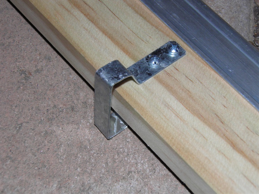
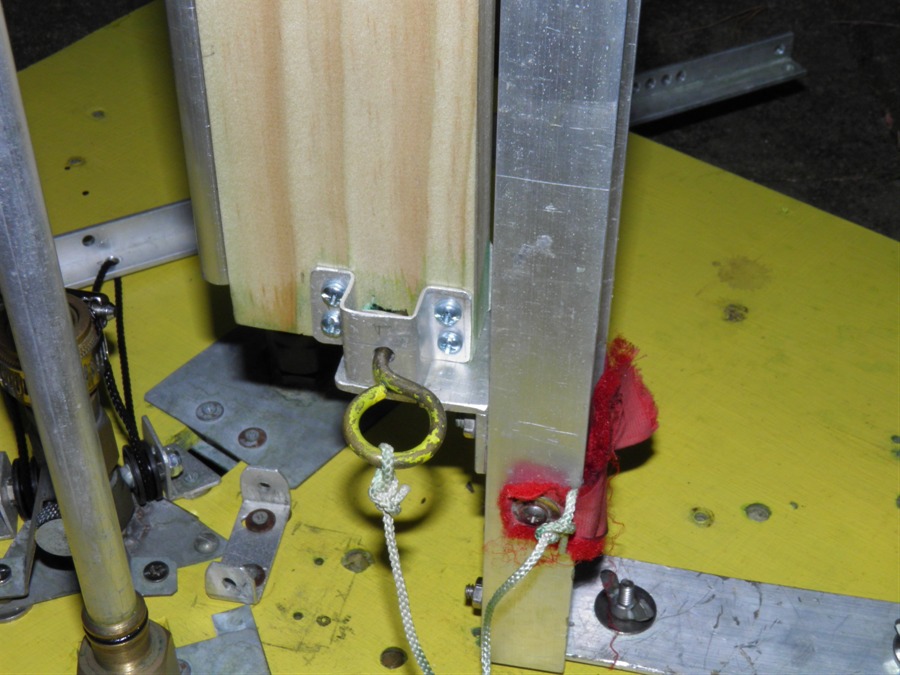
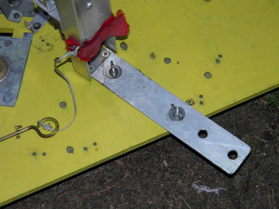
One of the rail buttons was attached to
the booster clamp and the other to a flat
plate that will be attached to the side of
the rocket.
Profile of the new rail
New rail buttons
Rail button attached to the
side of the rocket
Rail button attached to clamp
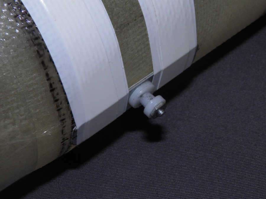
27 August 2013 -
We made 3 short aluminium tubes and glued
them to the side of the lower fairing. These
guide tubes are not load bearing but slip
over the top pins on the boosters. This
helps keep the boosters aligned with the
axis of the rocket during boost as well as
during burnout when the boosters start
sliding backwards. With the small loops on
the clamp, there is a real chance that a
booster could get snagged by the pins if
it did not slide out parallel. These guide
tubes ensure that both bottom pins are
aligned.
We also attached the booster parachute
release wires to the top of the fairing.
These slip into the booster deployment
mechanisms.
Guide tubes glued to the lowest
fairing
Booster Parachute release
wires attached to the fairing
Clamp held together with a screw
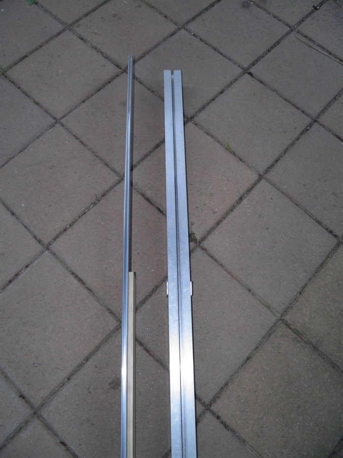
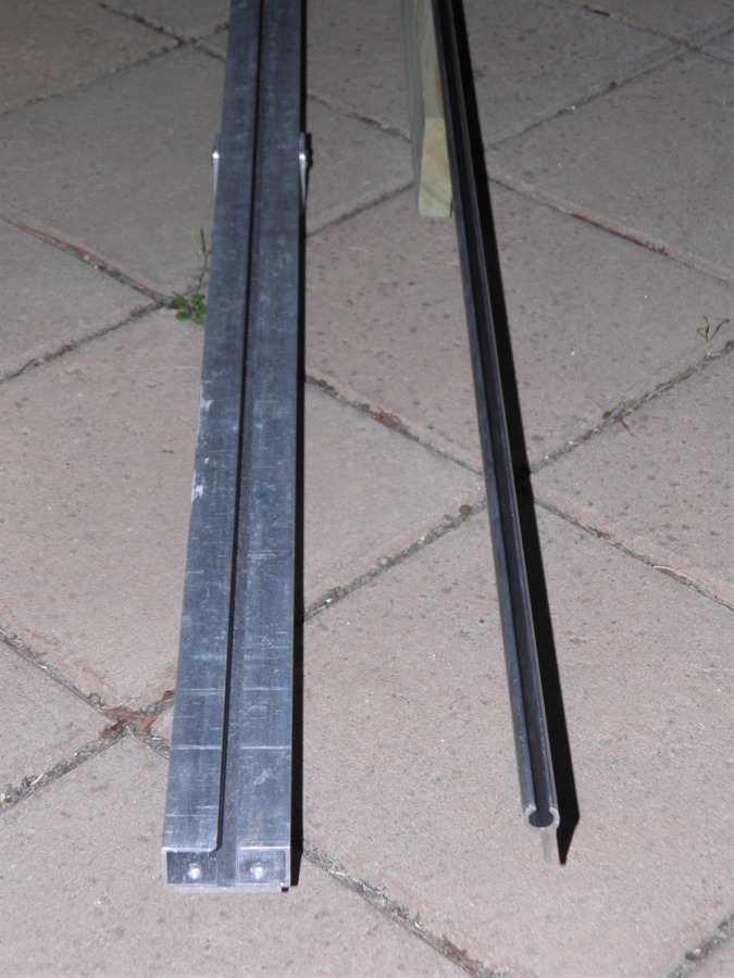
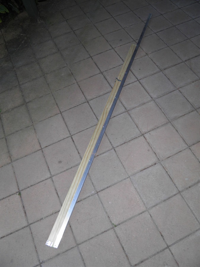
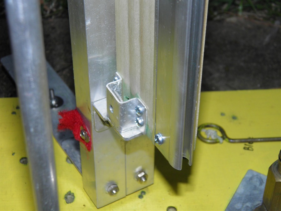
28 August 2013
- Today we made the guide rail. We had to
reinforce the rail with a plank of wood
because by itself the rail was quite
flexible. We made a couple of brackets that
would allow the guide rail to slip onto the
quick launcher legs.
New rail on the left,
old rail on the right
Comparison of old and new
guide rail profiles
The piece of wood is used
for stiffening the rail
The bottom bracket that fits
onto the
quick launcher
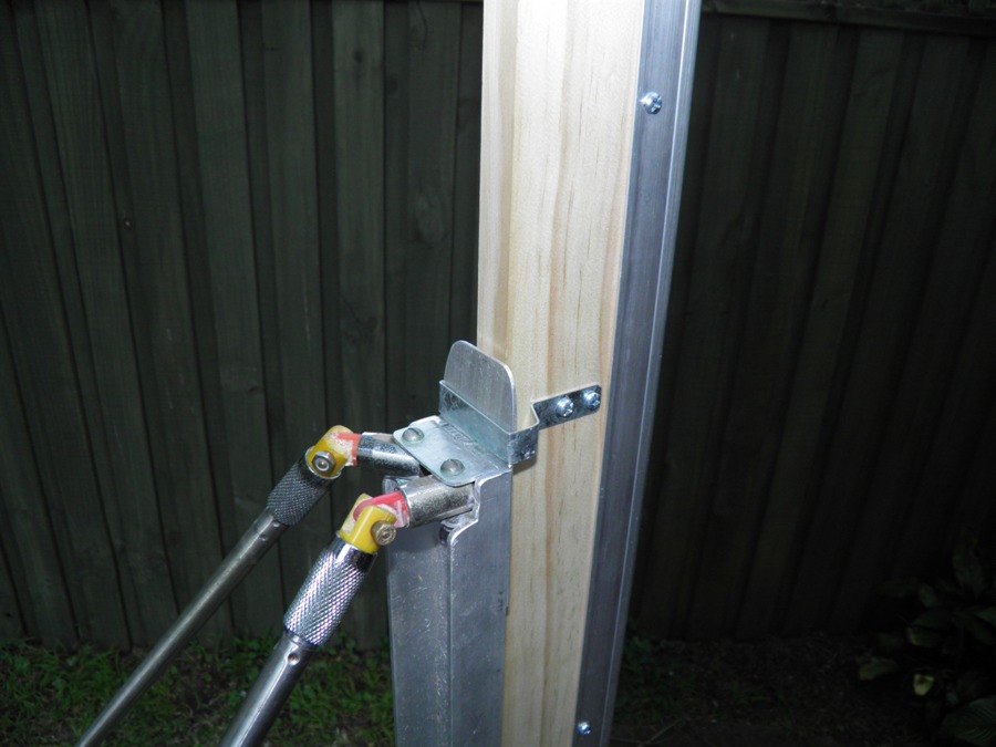
The top bracket for the quick
launcher
29 August 2013
- We attached the new narrow guide rail
to the launcher. We decided to use the quick
launcher legs this time rather than the
medium launcher legs, as these provide a
support point further up the guide rail
making it more stable. It is also a lot
easier to put up. The bottom of the quick
launcher legs is just held down with a couple of
wing nuts.
The guide rail is locked to the
legs
with a pin.
Pair of wing nuts hold the
launcher
legs to the launcher
Working into the night
The guide rail has to be removable so
that we can place it on the launcher after
the rocket is mounted. This just makes the
whole setup process easier.
Bottom bracket in place
Top bracket in place
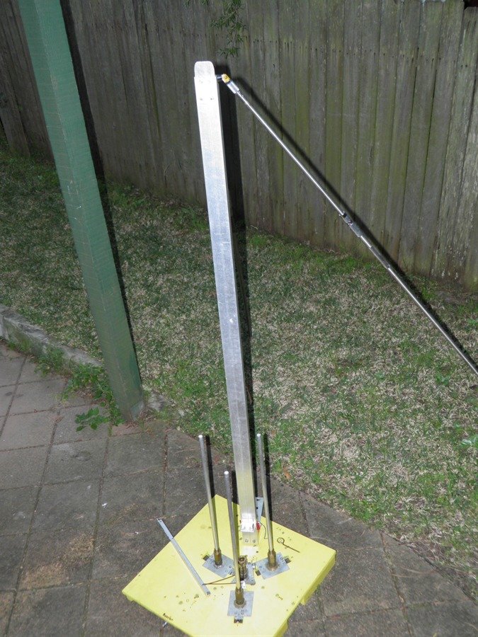
Cluster Launcher with
quick launcher legs
New guide rail fitted to
the quick launcher legs
30 August 2013
- We configured the new zLog mod 6
altimeter today to record at 10Hz. We used a
single LiPo battery to power it. The
altimeter was mounted in the middle fairing
to help protect it in the event of a crash.
We also mounted the HD #11 camera on the
side of the rocket on the fairing.
31 August 2013
- We launched the rocket a couple of
times today. The full write up of the event
is here: Day 137.
The booster clamp worked well so we can go
ahead and make a new one for the 110mm
diameter body of the Polaron G2.
Getting the Axion G4 ready
Boosters just separating
Pressurised to 120psi and 200psi
17
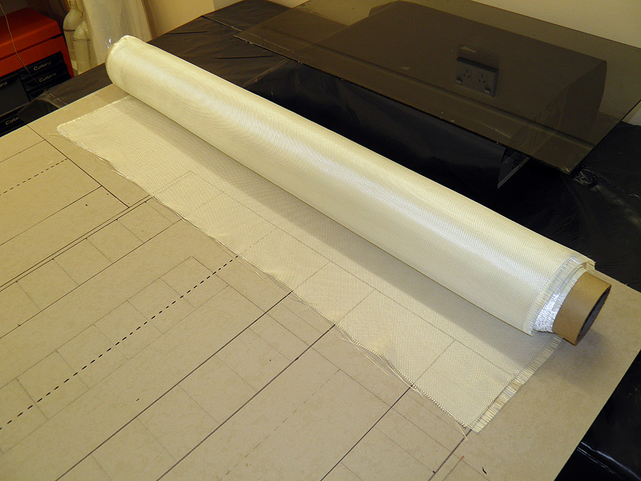
October 2013 - We bought
another 20m of 200gsm plain weave cloth
today for $189 as we will need more for
reinforcing the spliced quads. We have 5 of
the quads spliced together and ready to be
reinforced.
20m roll of 200gsm e-glass plain
weave
26
October 2013 - We
reinforced a couple of the spliced quads today.
This now gives us a total of 4 for the
boosters. We will make up another 3 (1
spare) and then we should have a full set
for construction.
Dad and I have also
continued discussions
about the launcher. We have been wanting to
make a new launcher with all nozzles
individually retained because of the loads
involved. After considering the
complications with ensuring simultaneous
release we decided to reinforce the current
launcher. The launcher is simple and has been reliable.
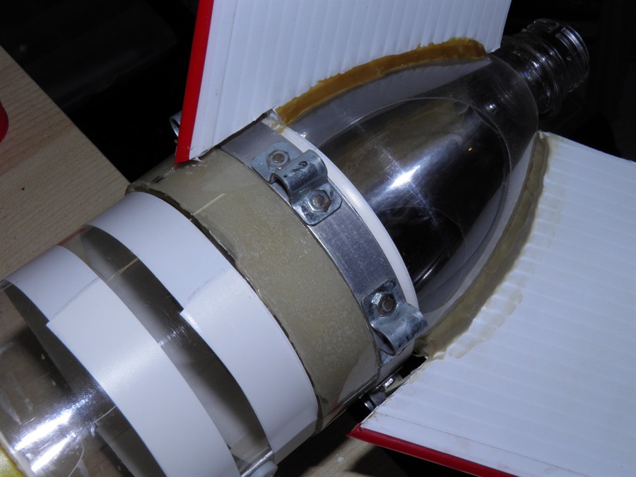
We will also need to reinforce the main
stage nozzle since it is going to be
carrying all the load. We are going to make
up a new nozzle that will protrude into the
bottle neck to help stop it from collapsing
and we'll make a new casing that will cover
the cap to help support the nozzle. We'll
also replace the rubber seal between the
bottle and the
nozzle with an o-ring.
Getting ready for more
fiberglassing
28 October 2013
- It's only 2 days later but we've redesigned the launcher yet again today. The
previous solution wasn't quite scalable for
bigger rockets or higher pressures. The next
launcher we build we want to use for future
rockets with more capability and the
previous solution would have only been acceptable
enough for the G2, We would have to
redesign the launcher again later anyway for the
new rockets. So we are
biting the bullet and we'll build the new
launcher for use with the G2. It will also
be a good way to test it.
The biggest issue is the exact simultaneous
release of all the boosters and the main
stage. We want to delay the release of the
main stage slightly after the boosters to
ensure the boosters are fully engaged when
the main stage is released. At higher pressures this becomes even
more critical as even small delays can
result in the boosters getting left on the
pad if the main stage takes off a little
sooner.
Another complication is that we want to
make the nozzle's radial position adjustable for different
sized rockets as before and allow for
some movement during pressurisation
as the bottles expand. We looked at the typical
way simultaneous release is done with low
pressure clustered rockets and
the one plate joining all the nozzle collars
together. However, this does not translate
well to high pressures where more force is
needed and still allow us to move the
nozzles in and out.
We also considered machining large
quick release connectors with ball bearings
to hold the nozzles, but the machining would
have been difficult because of the accuracy
required and would have
restricted us to a limited range of
nozzle sizes. The pull back force on the quick
connector collars also would have been large
especially with big nozzles and high
pressures. We also looked at
spring assisted releases for the plate, but
that would have taken a lot of force to
compress the springs initially.
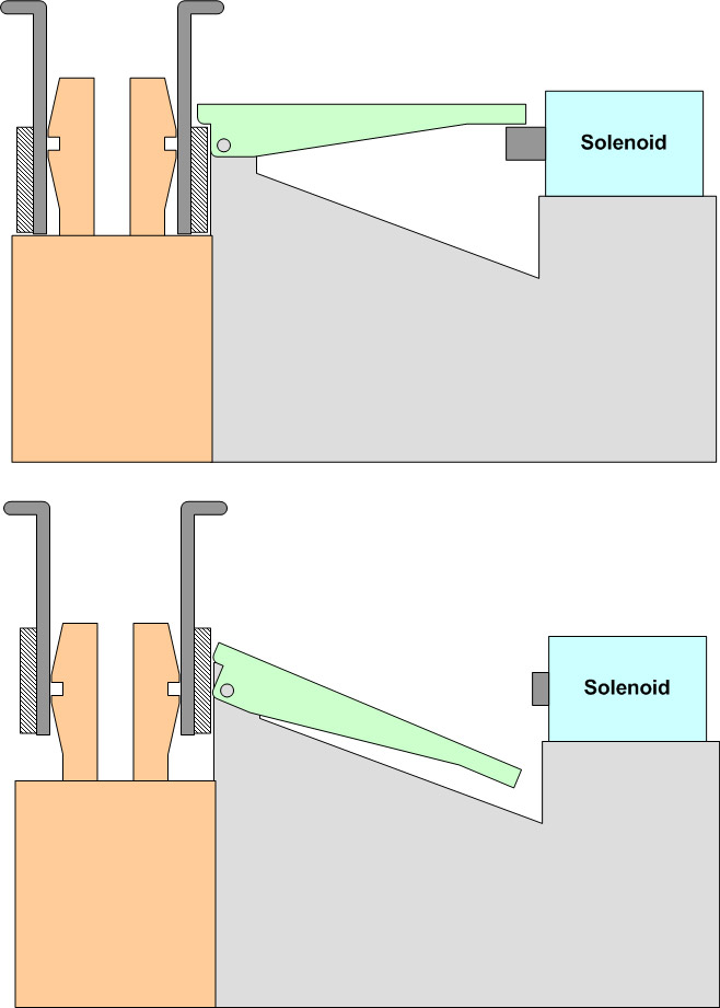
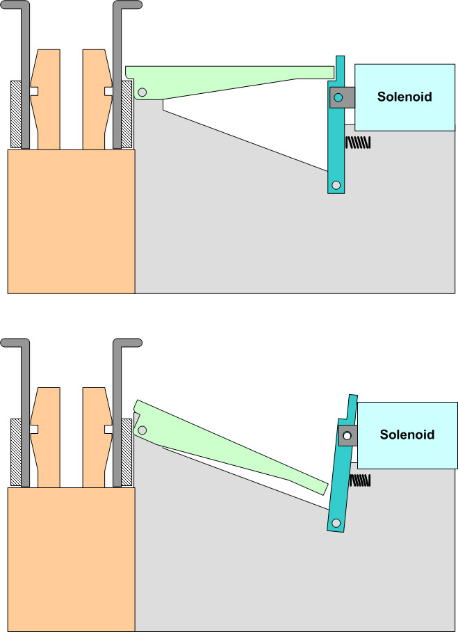
We finally decided on an electro-mechanical
approach to holding down and releasing the
nozzles individually. Each nozzle would be released by a
separate solenoid. The lever arrangement is
similar to a lot of spear guns.
This approach has a number of advantages for our
particular requirements:
We
can use the same nozzle and nozzle seat concept
as we have now with the Acceleron cluster
launcher.
We only need to glue an aluminium ring
with 1 or 2mm wall
thickness to the outside of the existing
nozzles.
The lever is normally dropped down so you
can put the rocket on the launcher
without a problem. You don't have to
compress any big springs.
Once the nozzle is in place, you lift the
lever to lock it and extend the solenoid
plunger to keep the lever engaged.
When you pressurise the rocket the lever puts a much
smaller force on the solenoid. Perhaps only
a few kg. Depending on the lever ratio. so
you don't need a big solenoid and not a lot
of power to drive it.
The force of the booster pushing up will
move the lever quickly out of the way once
released.
The whole mechanism is
attached to the nozzle seat so it can
slide in and out for bigger or smaller
diameter bottles easily as there is no
mechanical linkage to the other nozzles.
You can have as many boosters as you
like without a need to change the
release mechanism.
You can easily move the mechanism relative to the
nozzle seat for different size nozzles.
Because it is actuated electrically we can
synchronize all the nozzles at the same time
no matter where they are or how many you
have. We can also release the central one a
fraction of a second later to the
others.
If we use higher pressures then we can use
several of these mechanisms on each nozzle to
share the load. We could have 3 or 4 levers
holding down each nozzle.
There is no need for
very accurate machining, all can be
made fairly simply with hand tools.
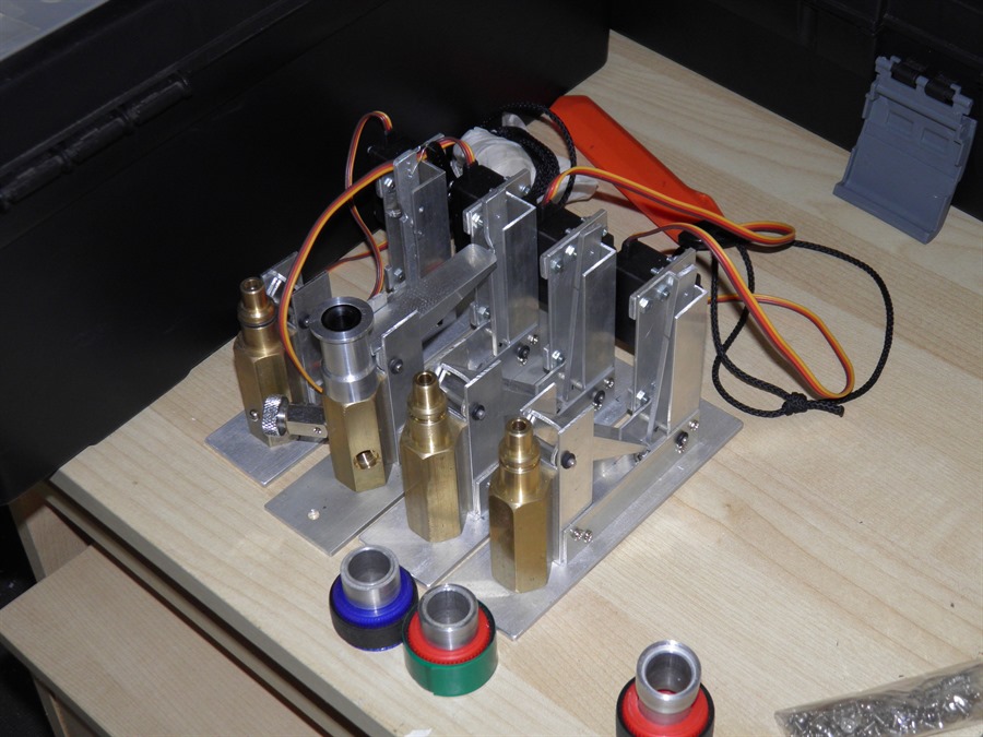
Electro-mechanical release with
solenoid
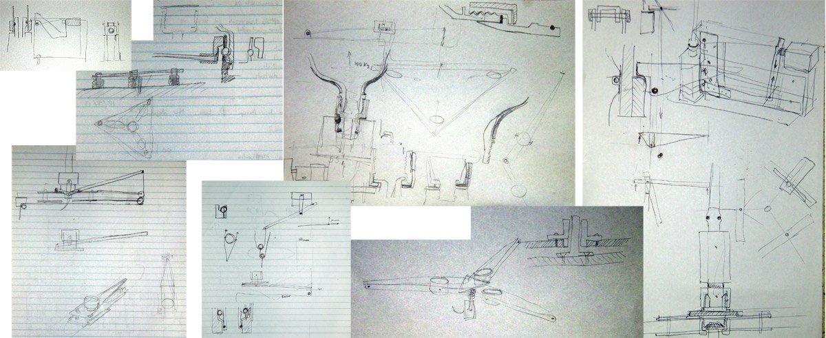
A small selection of some of the
launcher design sketches over
the last few months
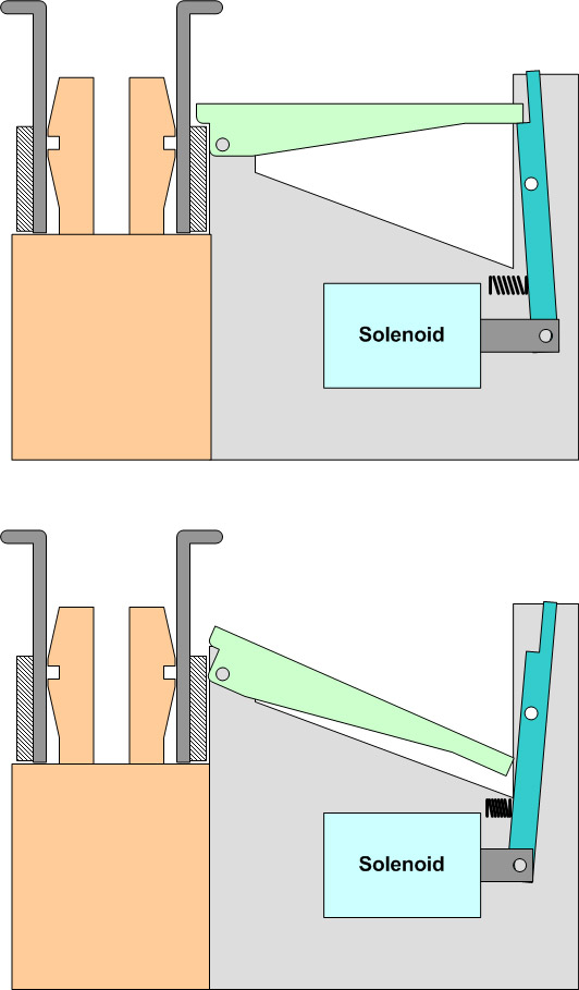
29
October 2013 - Added another refinement to the release mechanism
design to
remove the lateral load on the solenoid
plunger. This should also allow for greater
loads as the second lever holds all the load
instead of the solenoid plunger directly. A
small spring will be used to keep this
second lever positively engaged into the
main lever arm.
Solenoid release with secondary
lever
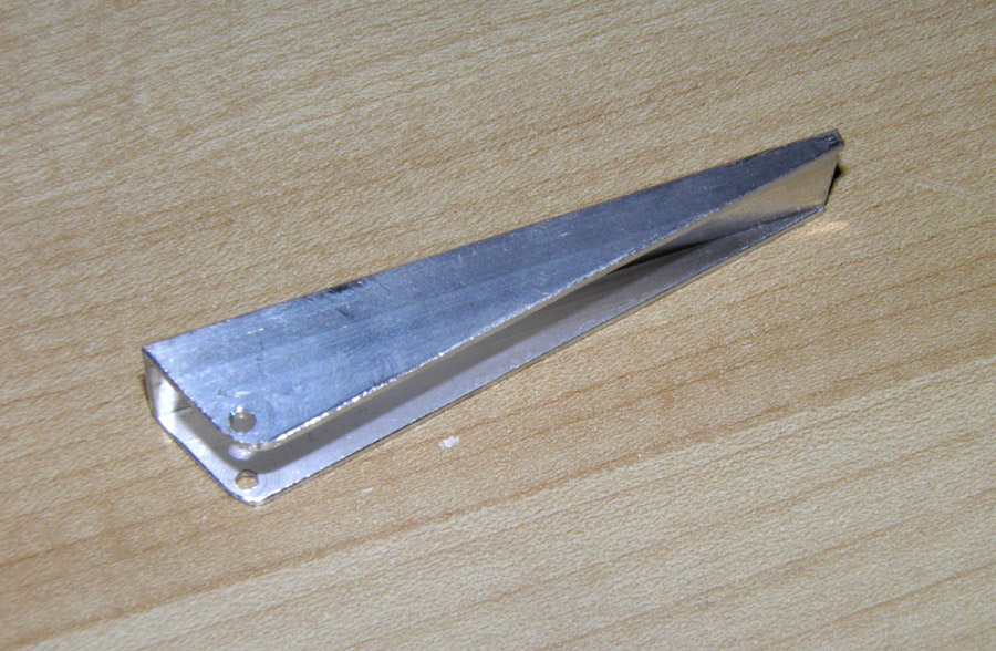
2 November 2013
- Today we bought a couple of aluminium
channels to start on the release mechanism
prototype. We made the lever and support to
test how well it would move. For the pivot
we used 2.2mm steel wire. After more
consideration we decided to switch this to
3mm stainless steel rod to help
spread the load more.
Prototyping lever
6 November 2013
- We cut out
more fiberglass for 2 more spliced quads.
Unfortunately we ran out of time to do the
actual reinforcing which will have to wait
till next week.
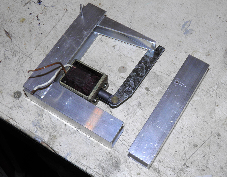
14
November 2013 - We further refined the
release mechanism today to make it more
compact. The solenoid was positioned under
the first lever and the
second lever was pivoted in the middle. This
will also help get a further 2:1 lever ratio
for the release. This also made it easier to
mount the lever and solenoid. We continued
to cut out the prototype parts to test the
mechanism.
Prototyping mechanism with
solenoid
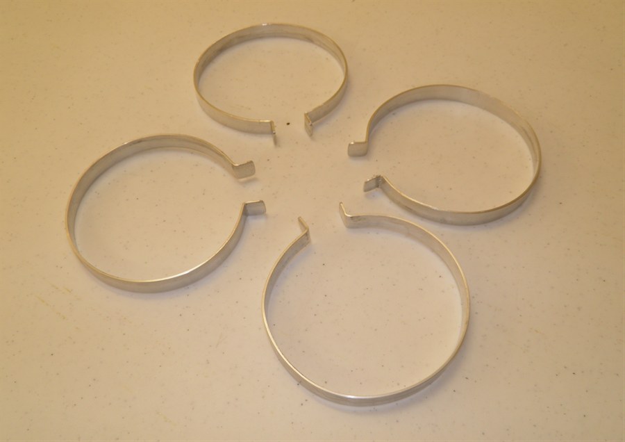
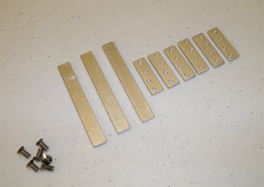
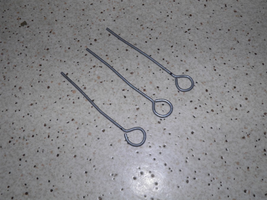
15
November 2013 - Made the loops for the
booster clamps. We are using 6 loops on the
bottom clamp with 2 loops for
each booster. These are the load bearing
ones. We are using another 3 loops at the
top of the boosters to keep them pointing in
the right direction. There are no
longitudinal loads on these only lateral.
Only one loop is needed for each booster at
the top.
Loops
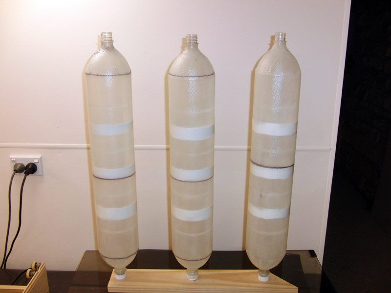
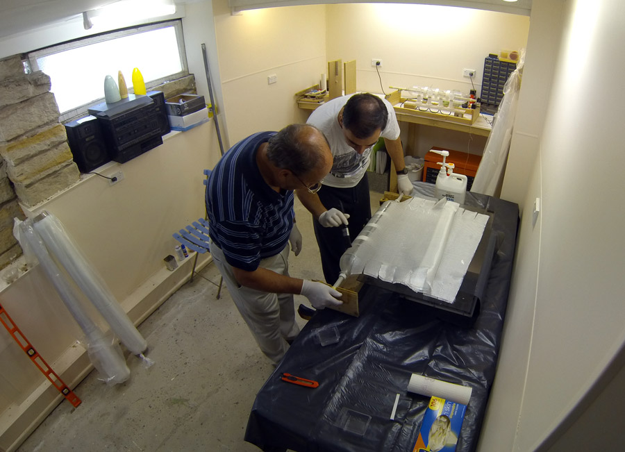
16
November 2013 - Dad and I spent a couple
of hours fiberglassing another two of the
spliced quads. That now makes 6 which
is enough for all the boosters. We still
have one more to do as a spare backup. It
takes us around 40 minutes to do the layup.
We used the GoPro's timelapse function to
film the entire process. (see below)
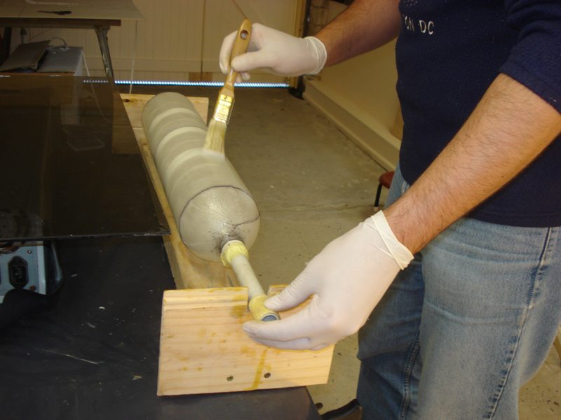
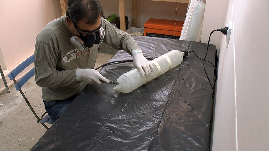
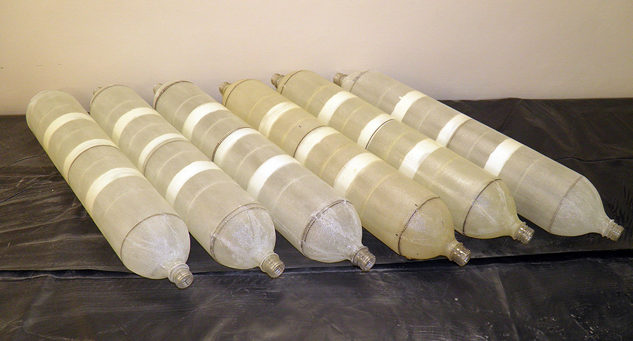
17
November 2013 - We sanded the 4 spliced
quads today with the Dremmel tool to remove
all the sharp bits sticking out. We'll need
to pressure test them next probably up to
250psi. I think we'll be aiming for 210psi
for the first launch, and if everything goes
well we'll increases the pressure again for
the subsequent launches.
Sanding the sharp bits off the
segments with a Dremmel tool
Six booster segments ready for
pressure testing
Here is a video of the
fiberglassing process:
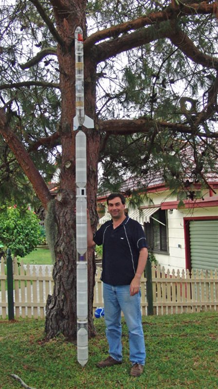
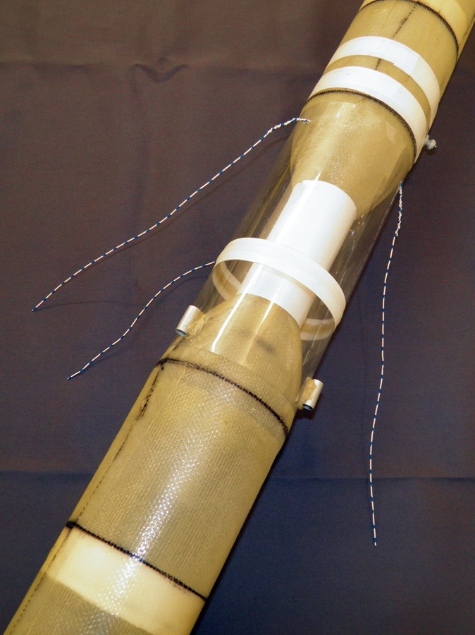
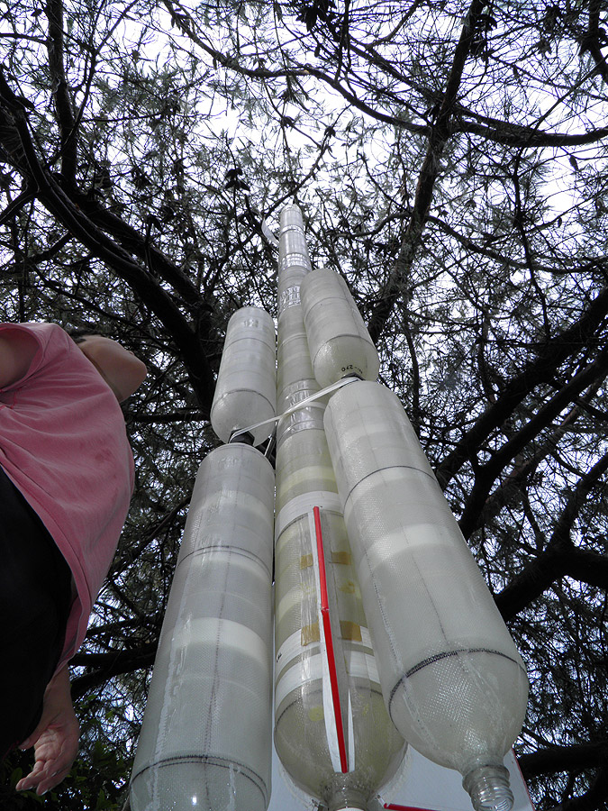
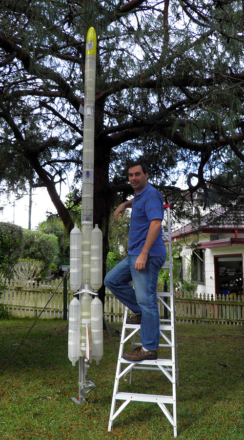
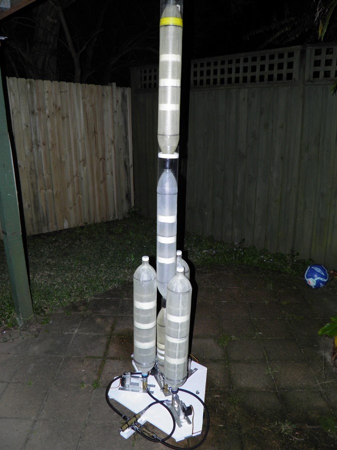
18 November 2013
- We test assembled the rocket today to get
an idea of the overall size and what kind of
access we'll have to the rocket. We just
taped the boosters to the rocket for the
photos below.
Just from a rough calculation the overall
capacity will be ~56L including the boosters
and will use around 16-17L of water. We also
ran the volume of air required through the
launches per tank calculator and found
out that at the eventual target launch
pressure of 250psi, we'll be able to only
get 2 launches out of a full 10L
scuba tank! This means we'll need to think
carefully about aborting launches (careful
prep) and will
need to bring at least a spare tank to the
launch.
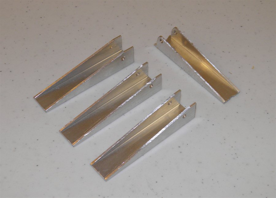
20 November 2013
- We made the first of the ring clamps
for the main stage today. This ring clamp
will transfer the entire booster thrust to the main stage.
It is made from 1.8 x 14mm aluminium flat bar
and weighs 25 grams. With the loops and
screws holding them down, it will be around
52 grams in total.
Main stage ring clamp
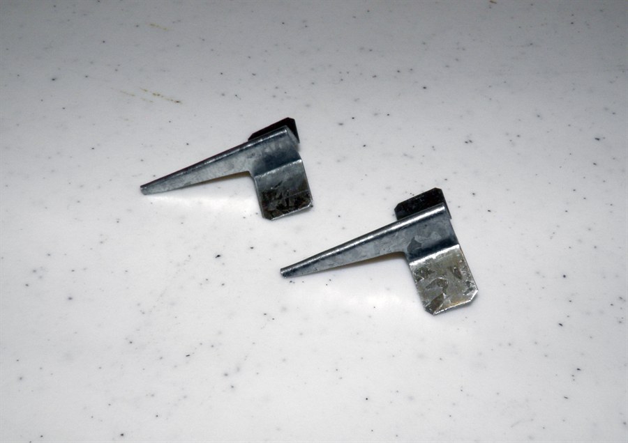
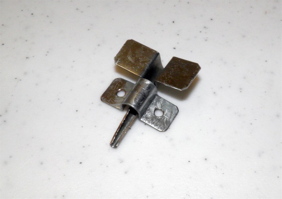
22 November 2013
- We made the rest of the ring clamps for
the boosters. These will have the pins
attached to them. We also made a couple of
the test pins so we can do some load tests against the loops. We are still not
sure how we will implement the top clamps,
loops and pins. These don't need to support
any thrust but are used to keep the top of
the boosters aligned with the rest of the
rocket. These mostly undergo small lateral forces.
Main stage and booster ring
clamps
Prototype pins to attach to
boosters
Pin and loop mated together
12 January 2014
- We replaced the 2.2mm steel wire with
3.2mm stainless steel rod as the pivot for
the lever arm. This should help distribute
the load better from the lever to the rest
of the release head. For this particular
launcher there will be over 300N applied to
this pivot pin.
New pivot pins
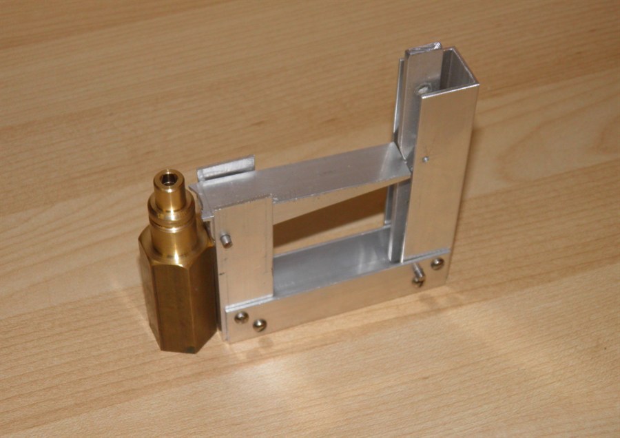
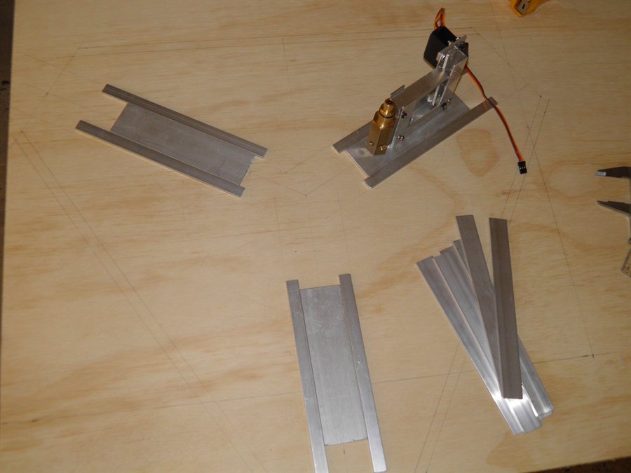
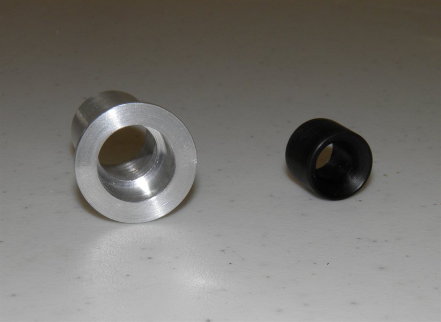
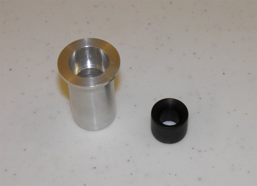
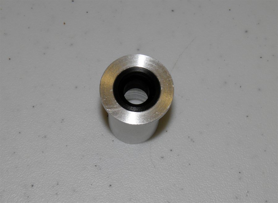
15 January 2014
-We machined the prototype nozzle seat today from a
7/8" brass hex stock. The
dimensions are the same as the cluster
launcher that we normally use as these will
fit the existing nozzles. The main
difference is that this nozzle seat has the
air inlet from the side rather than from
underneath.
This just makes it easier to mount and test
the prototype.
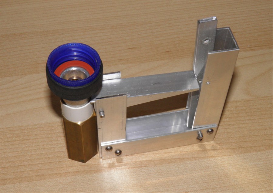
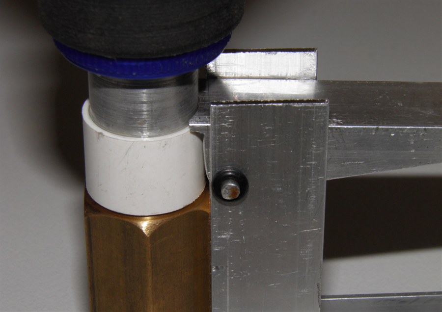
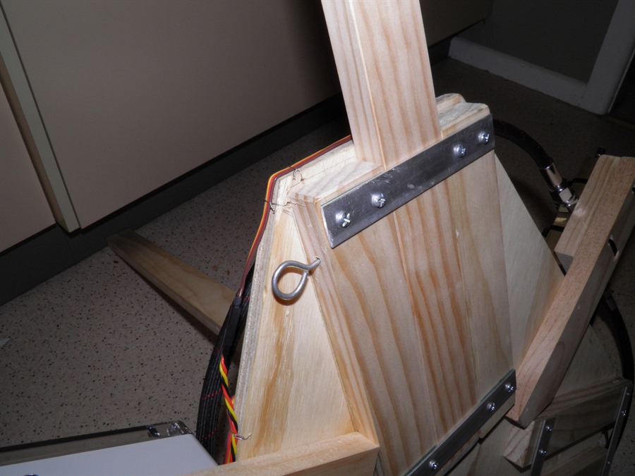
We also made a small PVC ring that will
go over the nozzle and will be what holds
the nozzle down.
Machining Nozzle seat
Nozzle seat finished
PVC nozzle retaining ring
It will be glued in place like
this
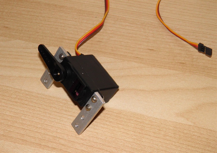
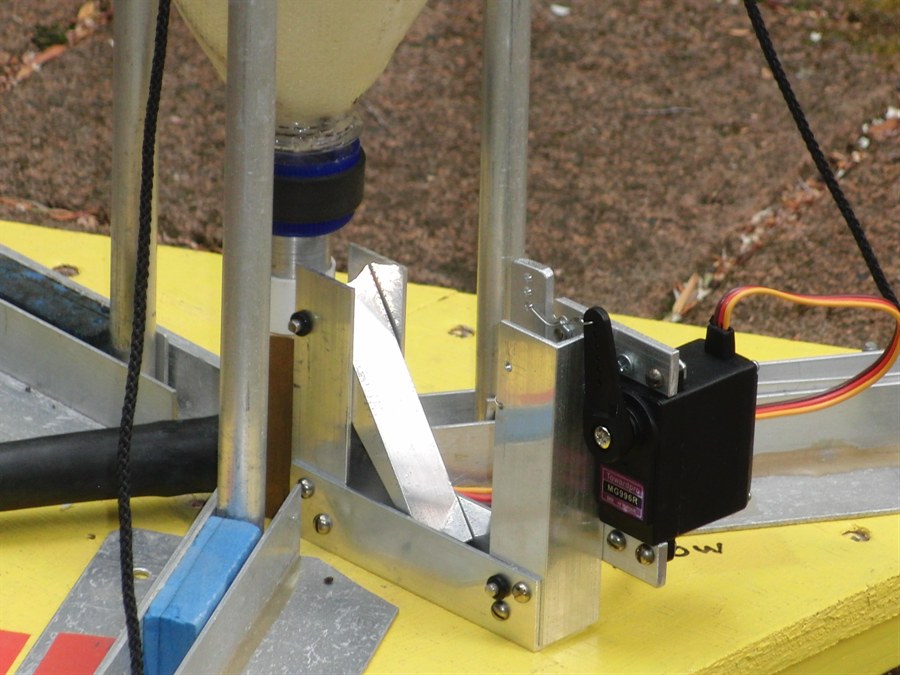
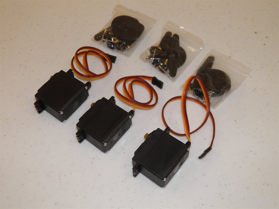
17 January 2014 -
We tested the solenoids we have and they
didn't supply quite enough pulling force to
have enough margin at the higher pressures.
So
we decided to mount a servo
motor on the side of the mechanism so that
we can test the release head and whether it
can hold down the nozzle at the full
pressure. For this test we went with the
release configuration described
here. If we later
decide to get larger
solenoids we'll replace the lever and
locate the solenoid on the bottom. The servo
motor we are using is a MG996R which is
quite strong at 10Kg/cm.
Nozzle seat attached to frame
With nozzle in place
Servo motor used for tests
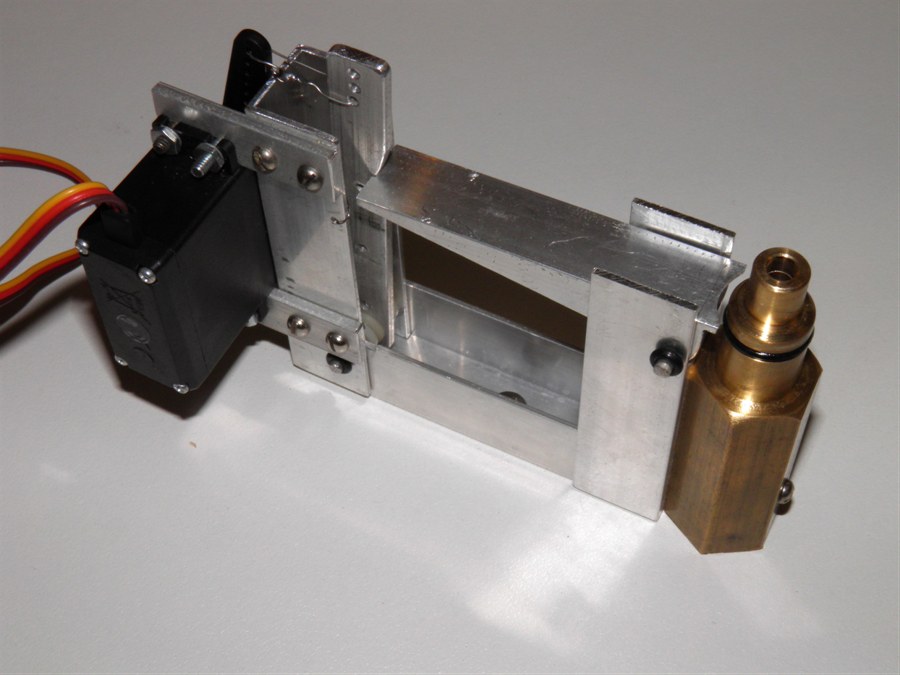
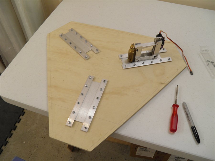
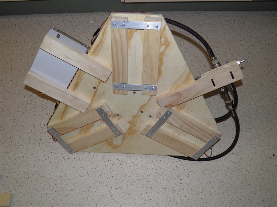
18 January 2014
- We finished making the changes to the
release prototype. The whole mechanism now
fits together and can be easily mounted. We
also glued the PVC ring to the nozzle with
the usual 24 hour epoxy.
Here the servo is attached
to the side of the frame
View from the other side
Close-up of how the lever grips
the PVC retaining ring
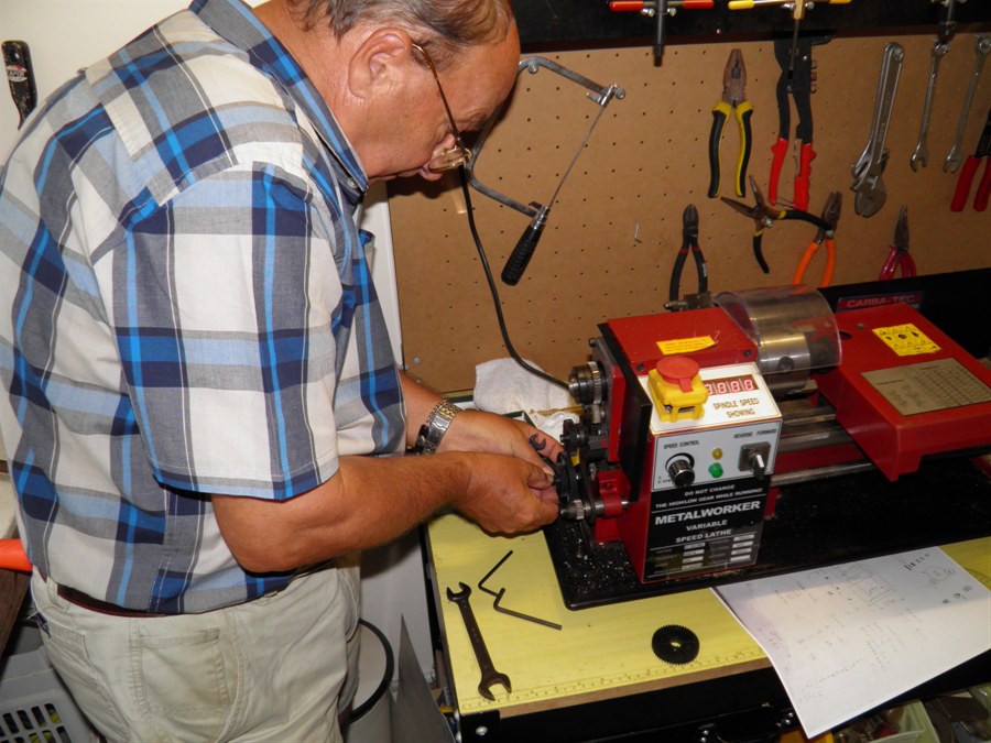
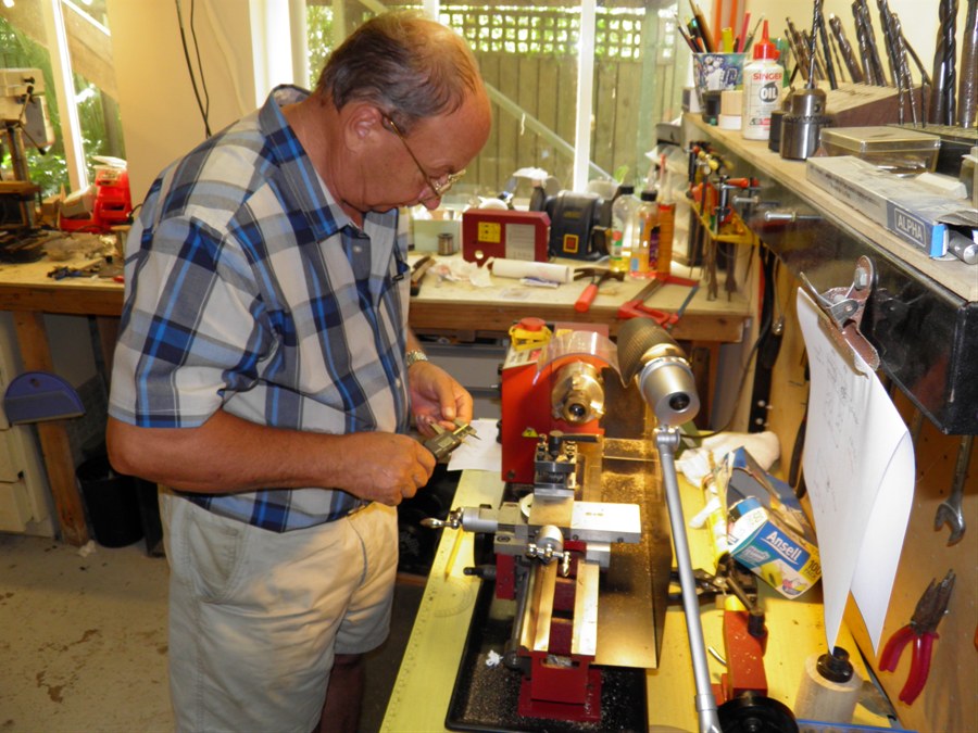
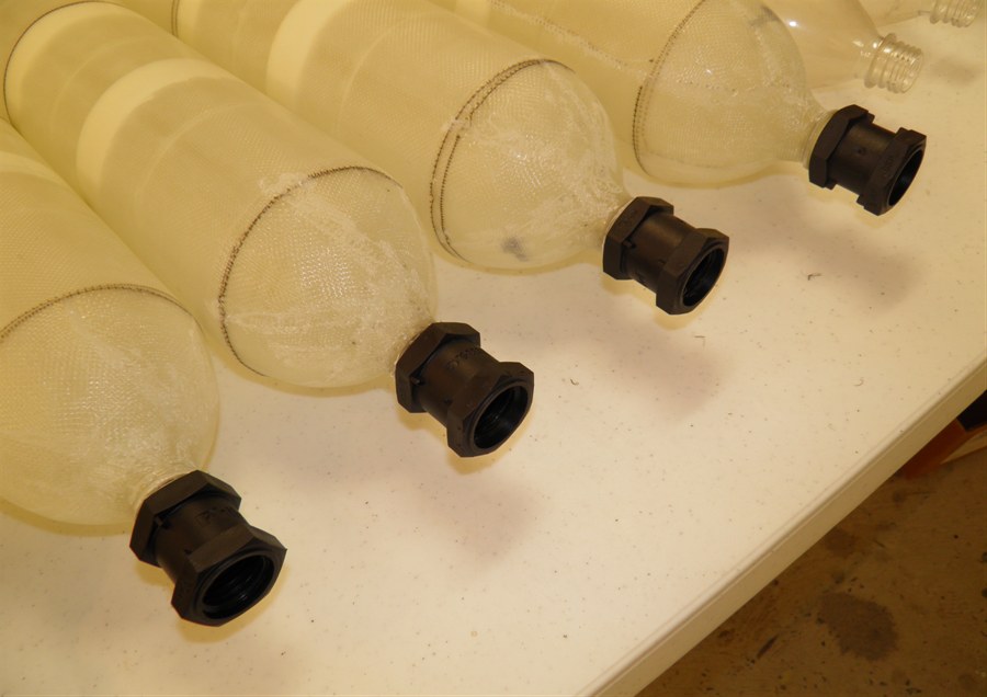
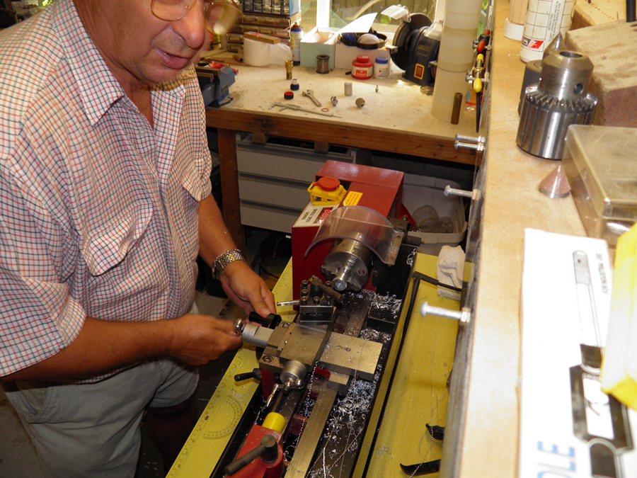
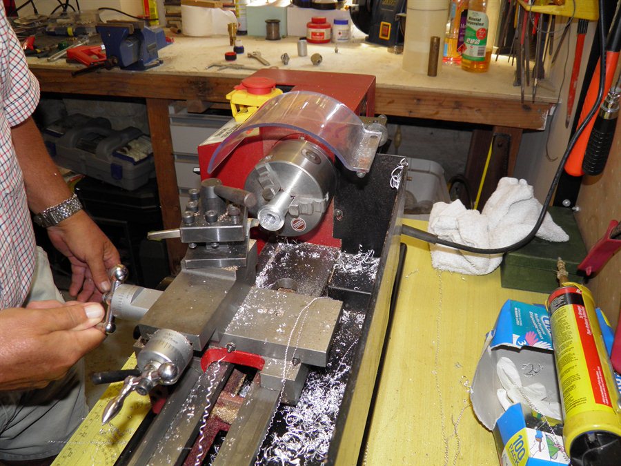
19 January 2014
- Dad
machined 4 new full-bore tornado tubes
today. It's quite an involved process and
took around 2 hours. We needed an extra 3
tornado tubes for the boosters, as our other
full-bore tornado tubes are tied up in other
projects.
We also finished making
the prototype release head today. The
release head was just screwed down to a flat
board for the initial tests. We used the
Servo Timer II with a remote trigger to
activate the servo. We put it and the 9V
battery in a plastic bag to protect them
from any water during the launch.
Dad changing the gears on the
lathe
to allow us to cut the right
threads
Dad machining the full-bore
tornado tubes.
Four tornado tubes ready for
action
The first
test was carried out at 20psi with air only
just to see how everything held up. The
release was clean with no problems. On the
second test we went up to 35psi again with
air only. This was also a nice clean release.
We then set up the old medium launcher and
mounted the release mechanism to it. We
wanted to test the release head at higher
pressures but didn't want the bottle flying
off into the neighbours yard so we tied it down.
The guide rails were meant to guide the
bottle so that it could clear the release
head vertically but keep it contained. The
first test was carried out at 100psi with
the bottle completely filled with water. The
test went well again and the release was
clean.
The last test was done at
200psi, and again the released head had no
trouble holding down the nozzle or releasing
it. Post test look at the PVC nozzle ring, and
the hold down lever arm showed no sign of
wear or bending which is good.
We reviewed the slow motion video of the
release process, and found that from the
time the servo timer gets triggered (LED
goes out) and the time the rocket starts
moving was around 62ms. This is pretty slow,
and we are hoping that if we'll need faster
action a solenoid will be able
to do better. The speed is important so that
all nozzles release simultaneously. Although
if they are all delayed by the same amount
then that should be ok.
Setting up to test the release
mechanism at full pressure
Here is a short video of the tests:
So good results overall and we are happy to
progress with making the rest of the
launcher and rocket. The focus is now on
getting this rocket and launcher finished
for the NSWRA high power launch coming up
fairly soon.
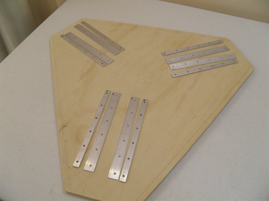
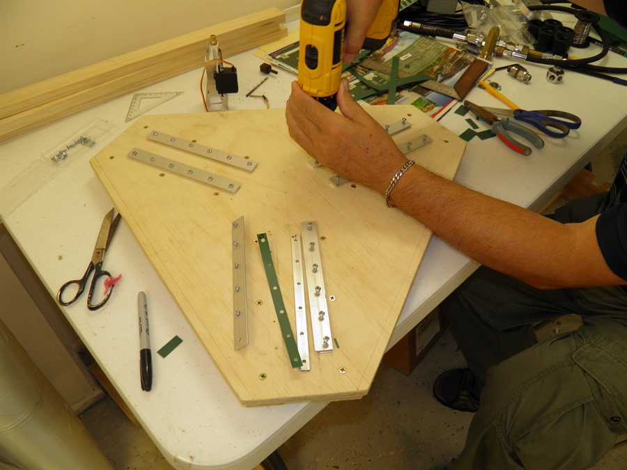
27 January 2014 - Lots of work done today:
Bought all kinds of materials for the
launcher, including aluminium extrusions,
the base plywood, and electronic bits and
pieces for the launcher.
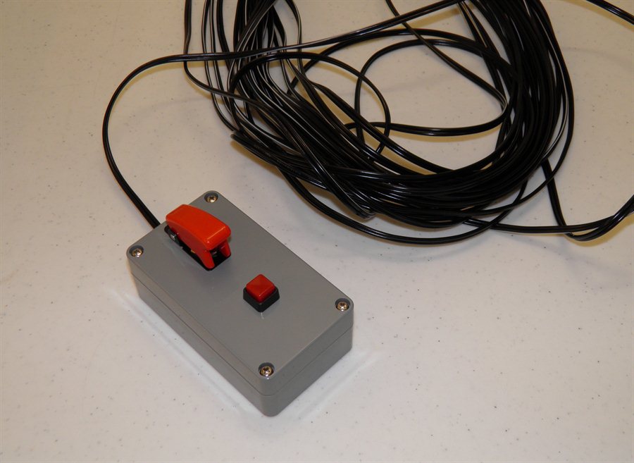
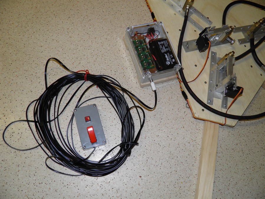
We made the remote launch control box with
the arm and launch buttons. The arm switch
uses the classic rocket switch protector to
prevent accidental firing. The controller is
very simple in that it only closes a wire
loop. The trigger is made in such a way that
you need to close the loop to fire. The arm
and launch switches are in series. This was
done so that an open circuit won't
accidentally launch the rocket. We also got
20m of heavy duty wire that will run to the
main controller at the launcher. The
intention is that there will be 4 Servo
Timer IIs to each control a servo. They will
all be triggered simultaneously, but have
perhaps 30ms delay. I'll update the firmware
so that instead of the configurable 1 second delay
increments, it will be selectable in 5ms
increments so that we get +/-30ms delay
range. That way we'll be able to tune each
release head timing to get a simultaneous
release of all 4. We'll use the high speed
camera to film the releases and adjust the
release heads as necessary. The main stage
will have a slight delay to make sure the
boosters are fully engaged.
Remote Launch controller
Booster clamps
Servo mounting brackets and
Secondary levers
The booster and main stage clamps have had their
M4 bolts put in. Each bolt holds the clamp
in place and prevents the clamp from
opening.
We cut out the remaining 3 servo motor
mounting brackets and drilled the appropriate mounting
holes.
We have decided on the mounting method for
the boosters that will allow them to slide
radially to fit different size rockets and
also allow for bottle expansion during
pressurising. On the old launcher we had the
slides go through the base, as the
air was being fed from underneath. This time
we are mounting everything on top of the
base.
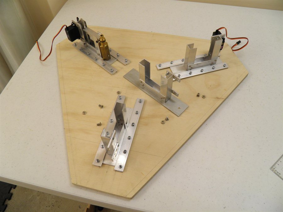
28 January 2014
- Made up more brackets for the booster
release heads.
We also made up the sliding brackets for the
release heads.
Sliding brackets for the release
heads
30 January 2014
- Today we cut the base out of a sheet of
plywood. The detachable legs will be mounted
underneath, and the launcher will be mounted
directly on top. The air for the boosters
and main stage will be fed through the top. This
makes the arrangement a lot easier and
requires less parts. We will use normal
scuba hoses and directly connect them to the
nozzle seats. Each hose will be connected to
a central distribution head. This again
simplifies the entire air inlet manifold,
and gives us the ability to easily switch
from single pressure to dual pressure system
when needed.
We also drilled out all
the holes for the slide brackets and located
them on the base. We wanted to make the fill
tubes removable so that the entire launcher
can be transported, but in the end we
decided to make the whole release head
removable so that the launch tube can be
permanently attached to the rest of the
release head. We will mount these last as we
want to carry out synchronization tests with
small bottles first.
Cut out base with drilled out
holes
in brackets
Sliding brackets assembled and
partly screwed down
31 January 2014
- We attached the release head bases to the
sliding brackets.
1
February 2014 - Made the main stage
release head framework and started
assembling the remaining booster release
heads. We also bought 500mm of the 7/8"
brass hex stock so we could machine the rest
of the nozzle seats. The off cuts we had
just weren't long enough. The brass was
bought from Edcon Steel for $25.
Release head frames are mostly
done
500mm of brass hex bar stock
4
February 2014 - We cut out the main
lever arms today and drilled all the pivot
holes. We also received two more servo
motors so we have enough for the whole
launcher.
Rough cut primary lever arms
New servo motors ready to be
mounted
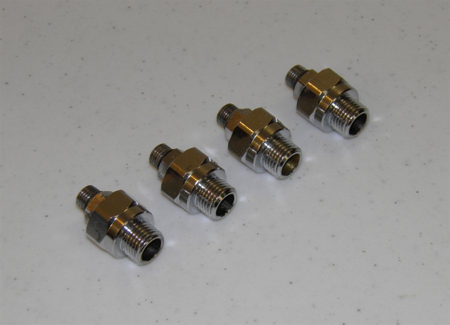
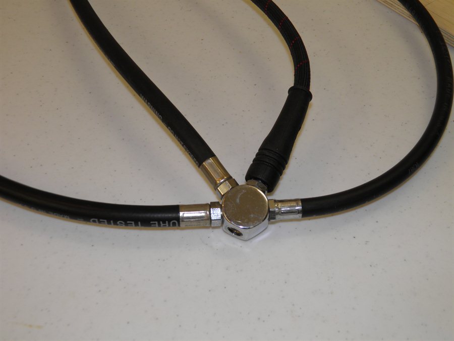
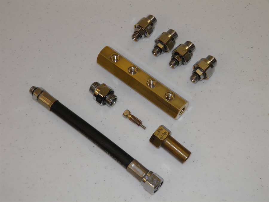
5
February 2014 - Dad made up a series of
scuba hose adaptors that will be used to
connect all the hoses to the launcher. We
had a radial distribution manifold that all
the hoses connect to that we were going to
use for the launcher, but after looking at
how the hoses sat, we decided to make a new
manifold that would make it easier to locate
the hoses.
Scuba hose adaptors
Radial distribution manifold
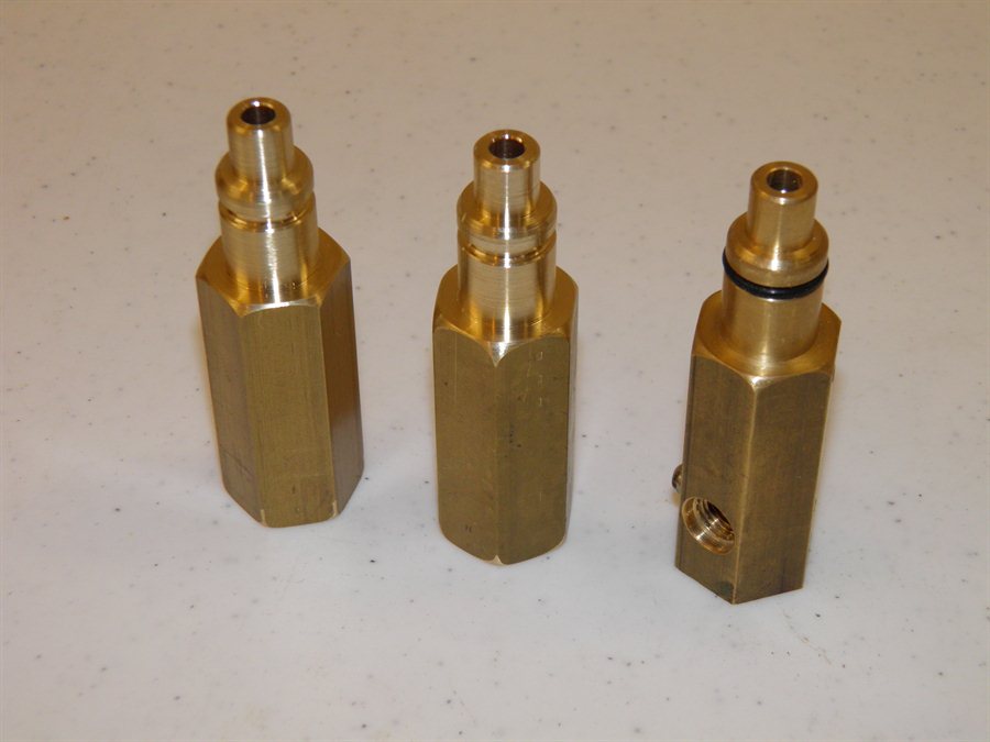
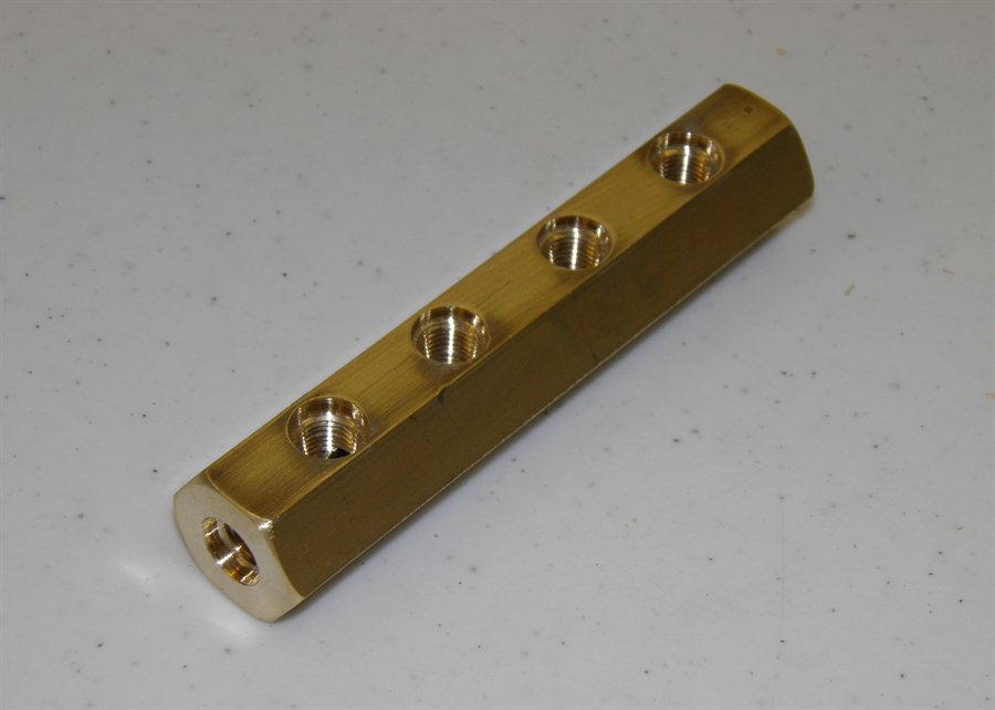
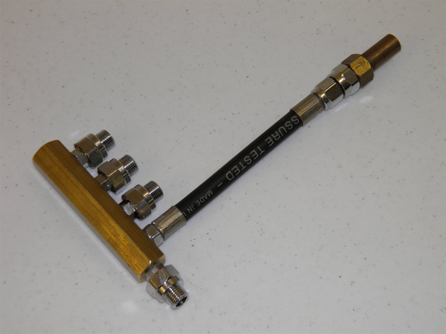
6
February 2014 - Dad machined up 2 more
of the booster nozzle seats today and made the hose
manifold as well. We need to run some
simulations first to see what nozzle size we
will use for the main stage. The original
static tests were done with a 9mm nozzle,
but we are likely to make that 10mm just to
increase the thrust of the main stage a
little bit. We need to be careful not to
make it too big because
the thrust should be lower than the boosters. With
the fill tubes acting as launch tubes, the
boosters actually produce lower thrust while
on the launch tube, than they do after they
leave it. The fill tubes are 12mm diameter
and the nozzles are almost 16mm. Dad also
found a non return valve lying around which
already fits the standard scuba threads so
that was an easy win. All the connections
use standard scuba threads so it makes it
very easy to connect, or reconfigure things.
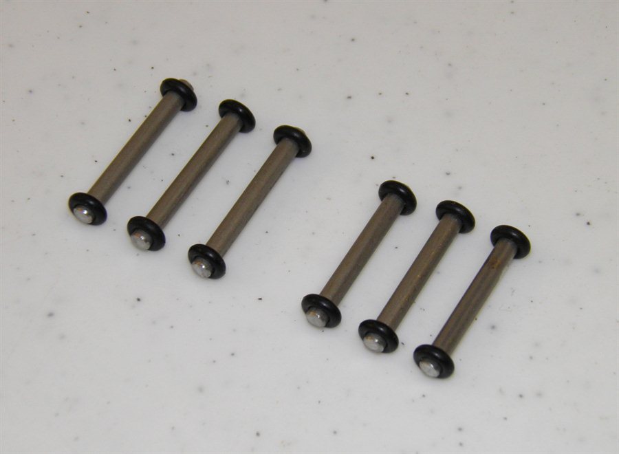
We also made the pivot pins
for the lever arms out of the 3mm stainless
steel rod.
New booster nozzle seats on left
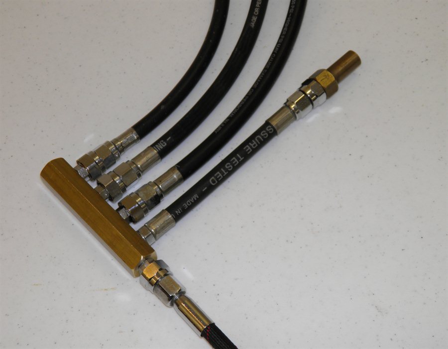
Linear distribution manifold
Non-return valve for the main
stage
Manifold components
Assembled with non-return valve
Booster hoses connected
Pivot pins for release heads
with
temporary o-rings to hold them
in place
We'll need to drill the hose connectors
next in the nozzle seats, but we have to see
which way the hoses will be connected first
so we can make the holes on the correct
side.
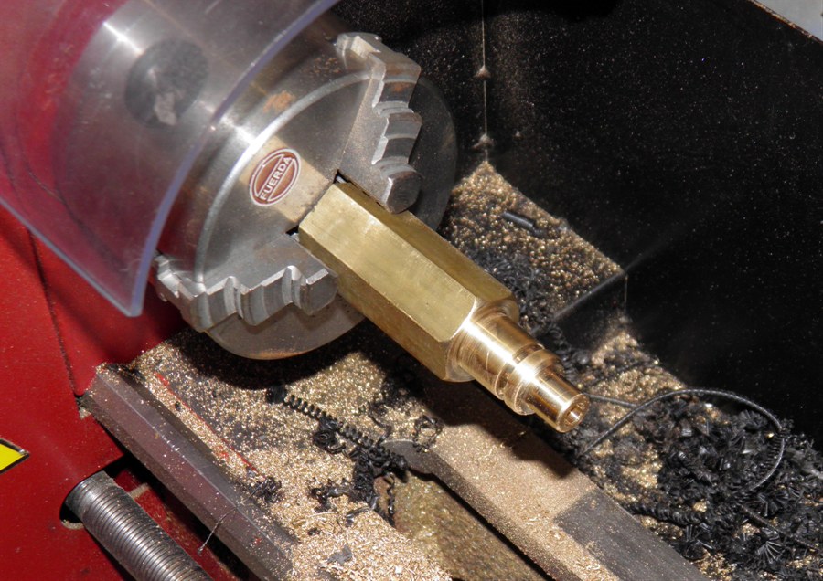
8
February 2014 - After much consideration
and simulations about what size nozzle to
use for the main stage and not coming to any
concrete solutions, we decided to make
the nozzle size adjustable. The problem is
that the nozzle seat must be machined to
snugly fit the nozzle diameter, if we wanted
to use different nozzle sizes we'd need
different size nozzle seats to match. The
release lever would also need to be changed
if the outside diameter changed.
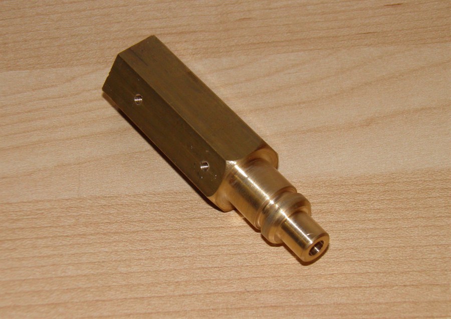
We settled on the same size nozzle on the
inside and
outside as the boosters so we could use the
same nozzle seat dimensions as well as release
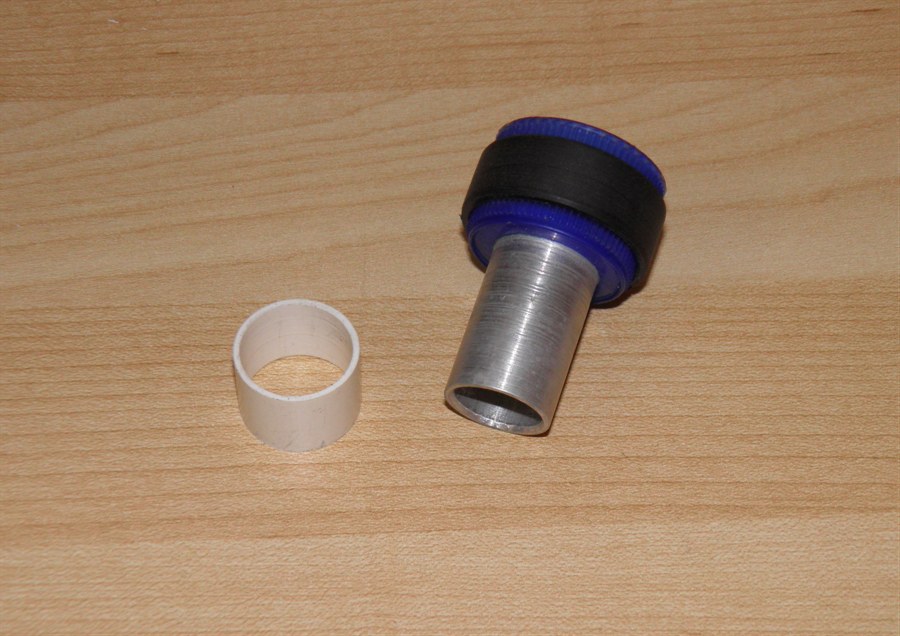
lever. We then
extended the nozzle by around 5mm and made a
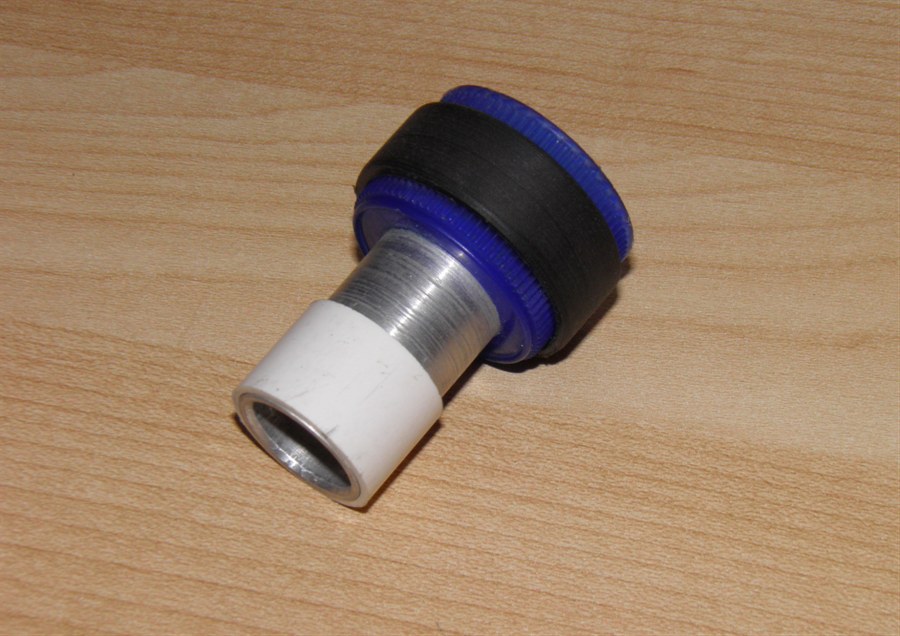
plastic insert with a smaller hole. This is
then press fit into the top of the nozzle. A small
ridge on the inside of the nozzle stops the
insert from coming out during flight. We can
now vary the main stage nozzle size simply
be replacing this insert. The nozzle size
can be varied from 2-13mm. The insert at the
moment has a 9mm hole. Dad machined the new
nozzle, insert and nozzle seat today.
Dad did a lot of machining on
the day
Here the main stage nozzle is
being made
The new main stage
nozzle
The plastic insert allows us to
change
the nozzle size
9mm insert press fit into the
nozzle
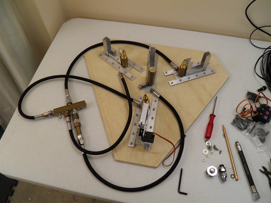
We also drilled out and
threaded the other nozzle seats to fit the
hoses. We had a few goes at laying out the
hoses so that they sat neatly. This is the
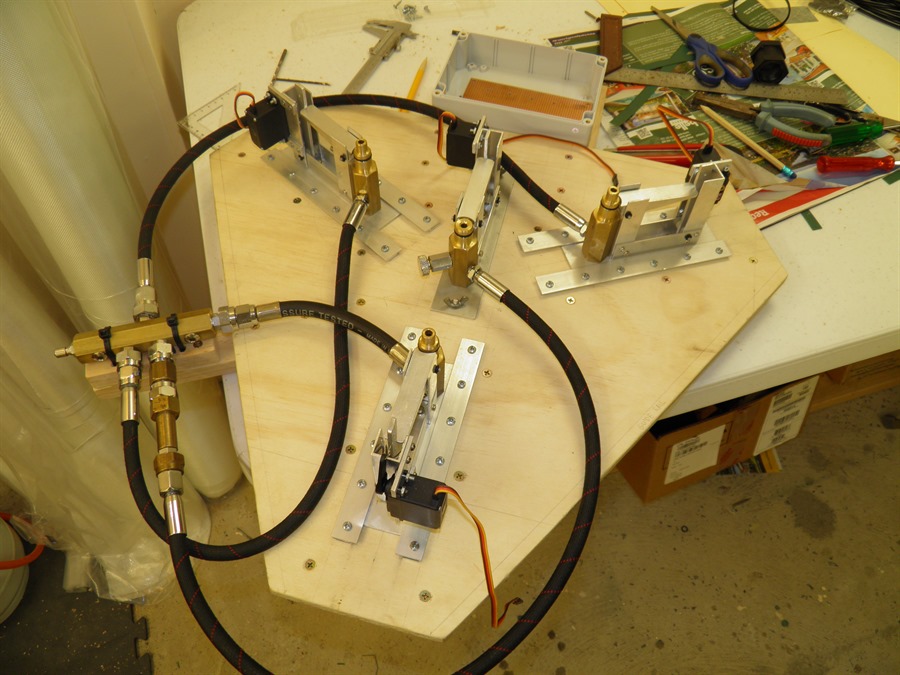
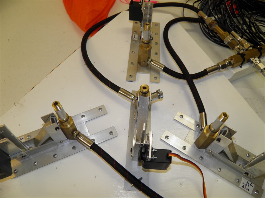
final configuration we settled on:
Trying out various hose layouts
The central release head is
still only
bar stock and no hose are
attached
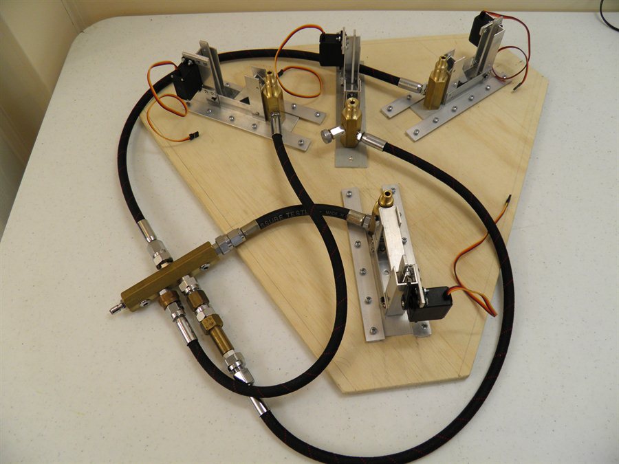
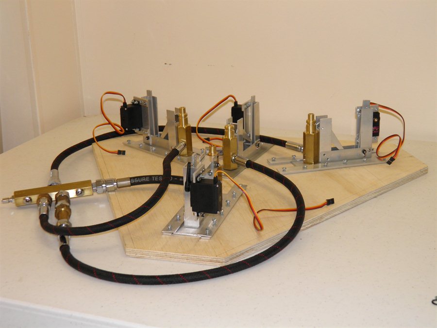
Final hose configuration with a
quick connector for the main
air inlet.
Side view with servo motors
fitted. The
air manifold is still to be
mounted.
Because the non-return valve prevents us
from depressurising the main stage remotely,
we added a pressure release valve on the
body of the main stage nozzle seat.
With the sliding independent
release heads we also realized we don't have
to arrange them radially, they can be
arranged in any other orientation so they
can be set up for 2 booster launches, or
independently all together and launch drag
racing rockets.
Lastly we also decided to replace the
plastic retaining ring on the nozzle with an
aluminium one that is 0.4mm wider. The
plastic ring was always going to be a
potential point of failure and so we will
machine new ones and glue them in place.
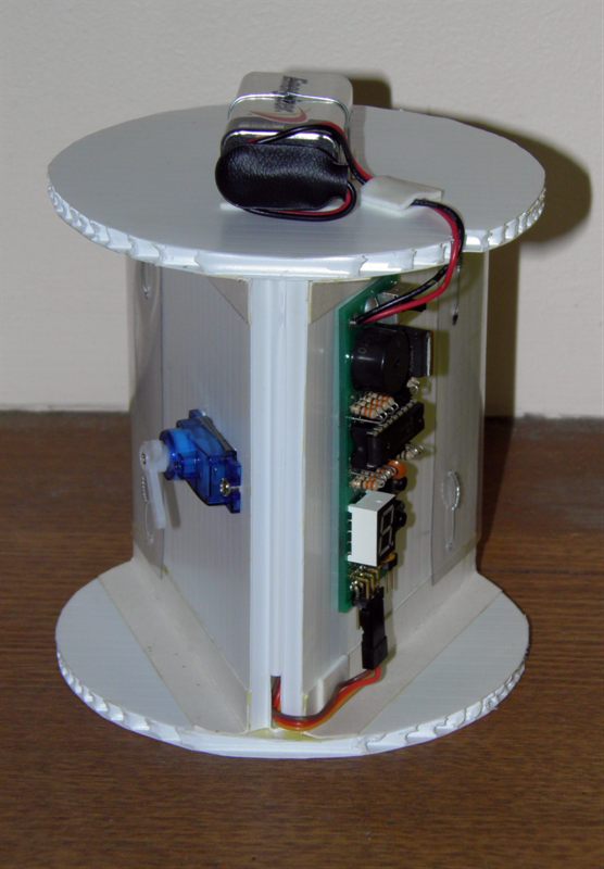
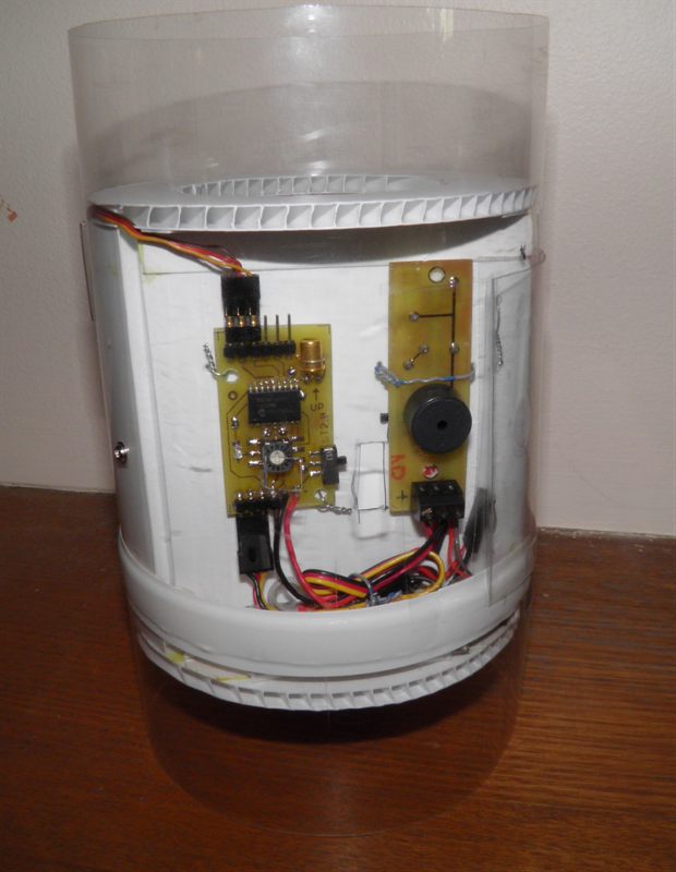
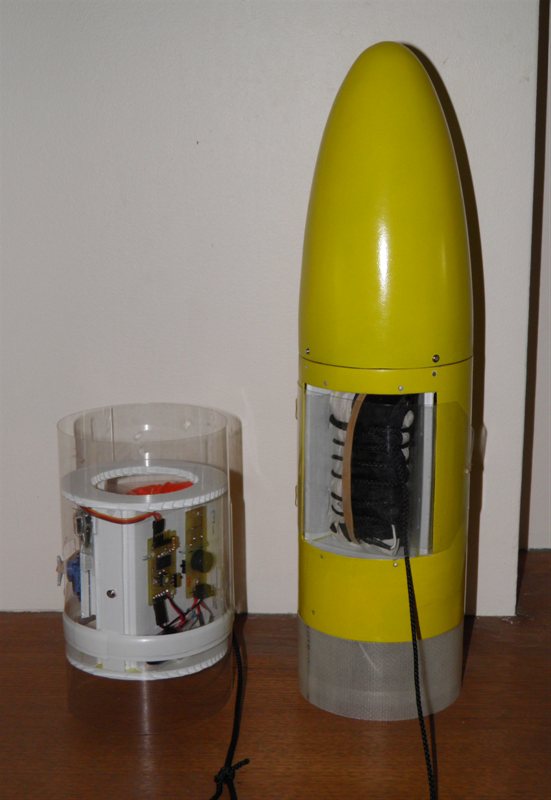
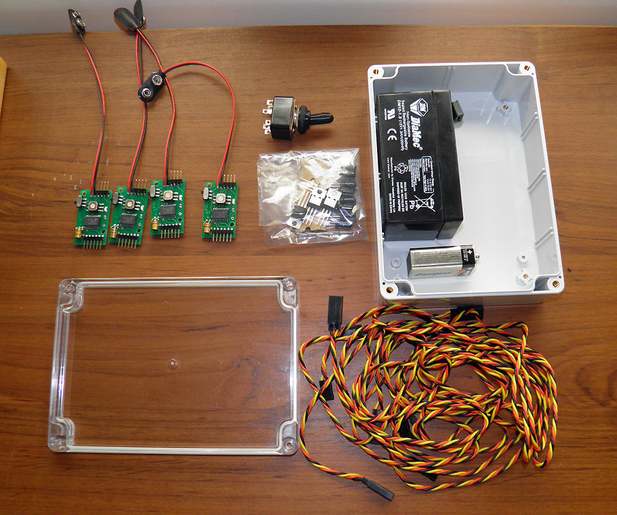
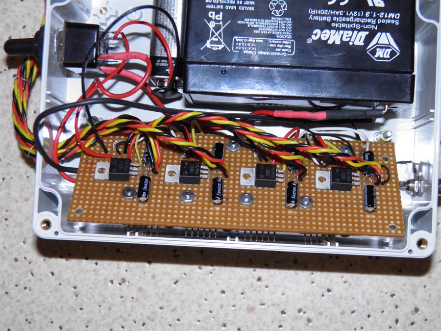
15
February 2014 - Started working on the
design of the electronics controller box. We
are putting the whole thing in a water proof
box with a clear top so that we can see the
status LEDs on the servo timers. The power
source for the servo timers is a standard 9V
battery. For the servo motors we are using a
1.3Ah 12V SLA battery. We expect that each
servo could potentially draw about 1 Amp so
we are using the bigger battery to power
them. Each servo will have its own 5V
voltage regulator to deliver the needed
current. We could have gone with LiPo
batteries, but we already had two of these
small SLA batteries so we decided to go with
that. There will be a single power switch to
turn everything on. We are using a rubber
waterproof cover for the switch as well. We
are using RC servo motor cable extensions,
of which one end will be soldered directly
to the board inside the case and the other
will have the male adaptor to connect
directly to the servo motor. We have opted
not to add another set of plugs to the
connections to reduce the chance of an open
circuit. The remote trigger will be
connected via an RCA connector which should
be relatively splash proof.
19
February 2014 - We have assembled all
the electronics pieces and have started
planning the internal layout in the box.
With the cover off it will be possible to
adjust the timing on the individual timers
to synchronize all of them.
Components for the control box.
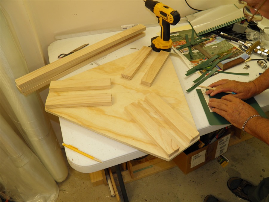
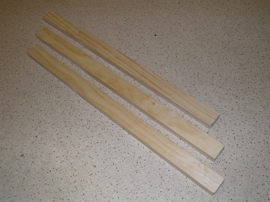
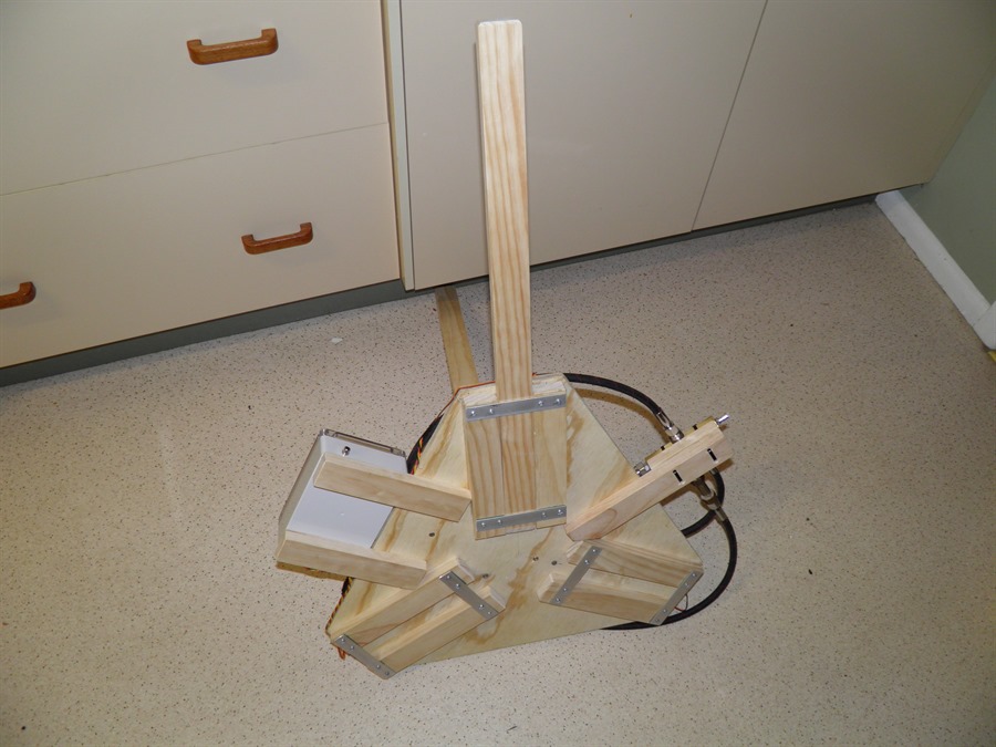
23
March 2014 We attached leg brackets to
the bottom of the base today. We decided to
make the legs removable to make it easier
for transportation. The legs were also made
from wood. The rocket will be held up by the
quick launcher guide rail so the launcher
won't need to be holding up the entire
rocket.
Mounting leg braces
Legs
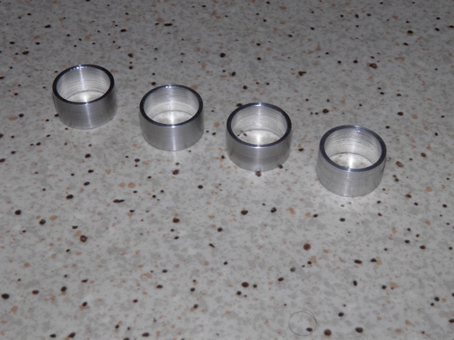
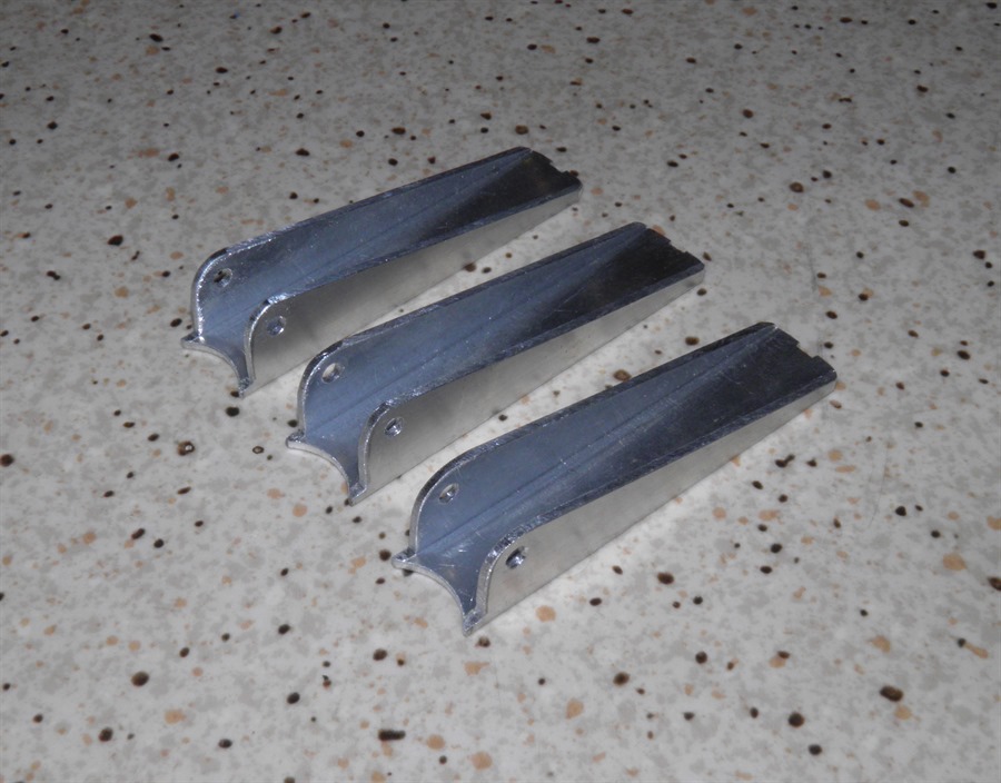
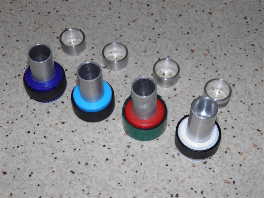
29
March 2014 - Dad machined up the other
three nozzle retaining rings today. They
will be glued into place once they are
fitted to the nozzle caps. Once these are
glued we won't be able to take them off the
caps. We also made aluminium brackets that will
hold the legs to the bottom of the base.
After much consideration of how to secure
the legs in place we decided on a simple
wire pin from the side made from coat hanger
wire. The pin is slightly bent which
prevents it from falling out.
We also made 6 shims to go
under the release mechanism slide mechanism.
This allows the release mechanism to slide
freely. The shims are 0.6mm thick and made
from a plastic folder. We used the same
shims under the leg brackets to let the legs
slide in easily.
We also attached brackets to
hold the air manifold as well the control
box to the base. The remaining 3 primary
levers for the other release mechanisms were
also made today.
Nozzle retaining rings
Attaching shims
Air manifold and control box
supports
3 new primary levers
Leg fitted into base
Bent pins to keep them in place
Pin in place
Bottom of launcher
2
April 2014 - We bought new nozzle caps and
made holes large enough for the nozzles. We
spent quite a bit of time looking for the
different caps so that they had a full
thread going all the way to the edge. We'll
see how these stand up to the pressures. We
are using plastic reinforcing rings on the
outside of the cap to help keep the thread
engaged.
New nozzle caps
Levers fitted to release
mechanisms
4
April 2014 - We built the control box today.
The 4 individual power supplies for each of
the RC servos were built on a veroboard and
the servo timers were mounted on the back of
it. This allows it to be easily mounted in
the box. The batteries, switch and
connectors were also mounted in the box. I
added the linkages between the servo horns
and the secondary levers. These have to be
fairly strong, flexible and not stretch so I
used some multi-core wire and soldered a
loop of it to join the two together. After
programming the individual timers start and
end positions we tested the whole setup. The
tests went well and all 4 release mechanisms
looked like they released at the same time.
We'll do proper tests under pressure with
the high speed camera and only then we'll
know if the timing is right.
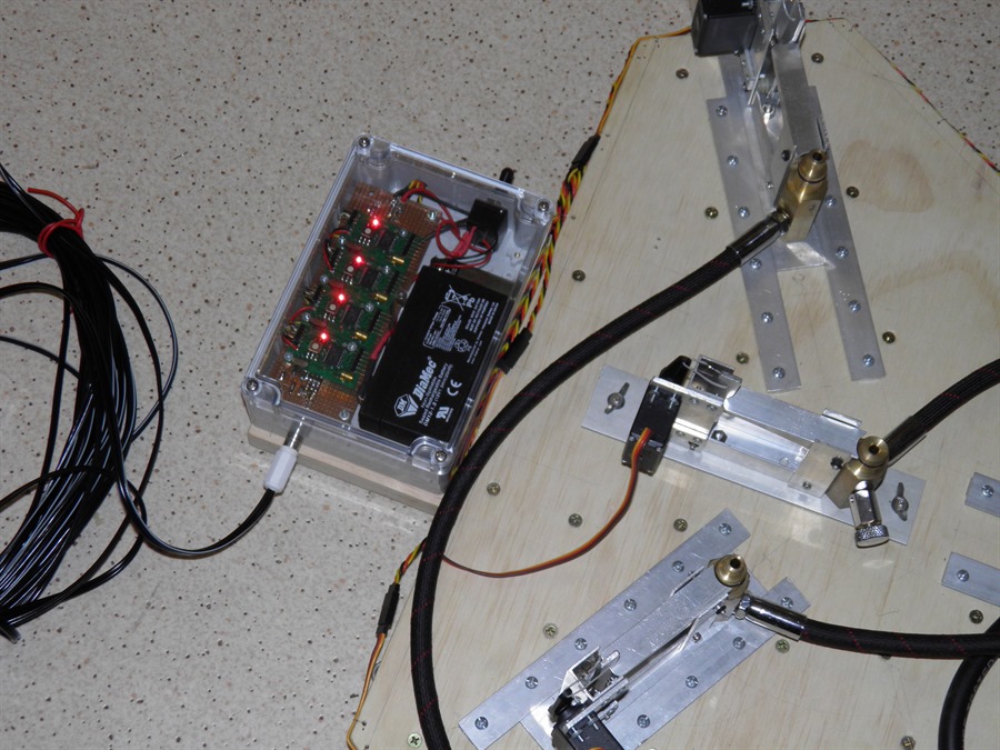
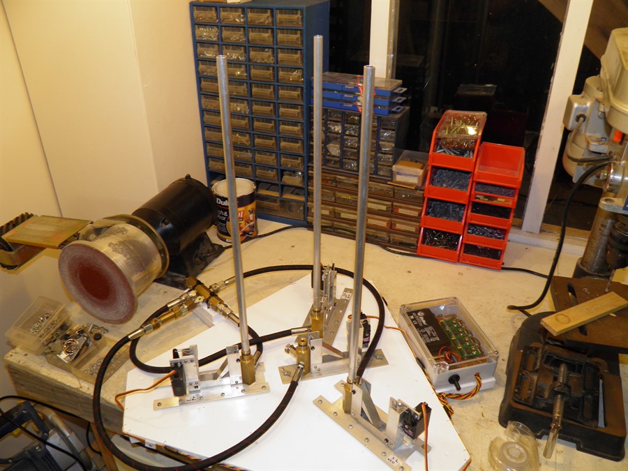
Completed control box
Powered up (4x STII)
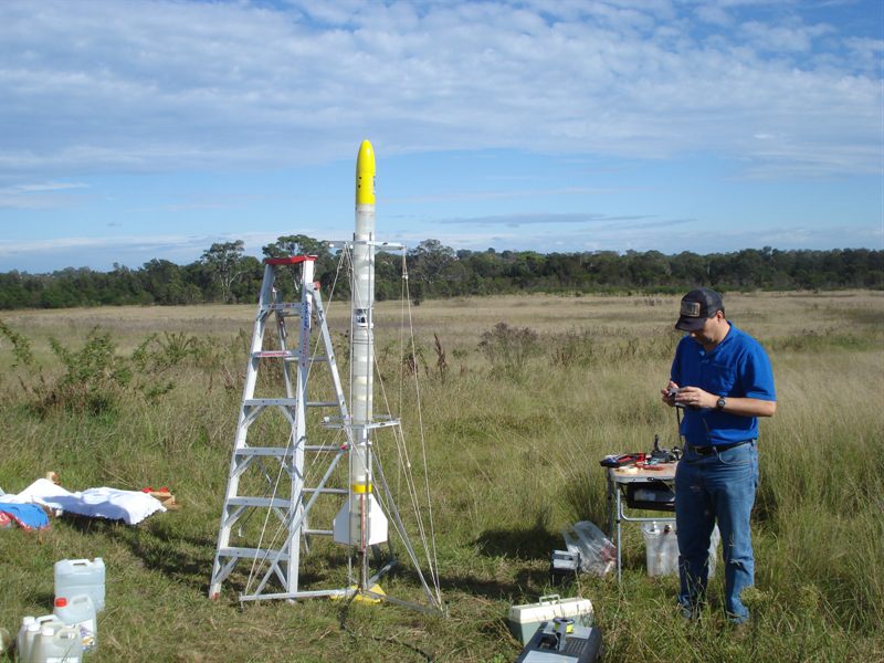
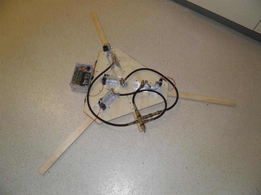
Launcher ready for testing
Detail of power supply for servo
motors
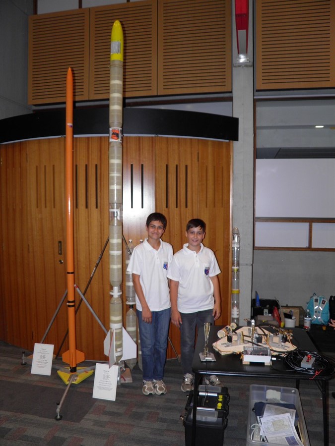
5
April 2014 - It was the
Macquarie University astronomy open night.
so we brought our rockets and the new
launcher for show and tell. We used the
demonstrations on the night as a good test
to repeatedly go through the launch
sequence to see if anything broke or came
loose. The launcher
also survived transportation to and from the
event which is always
a bonus.
Testing launcher repeatedly at
the
Astronomy open night.
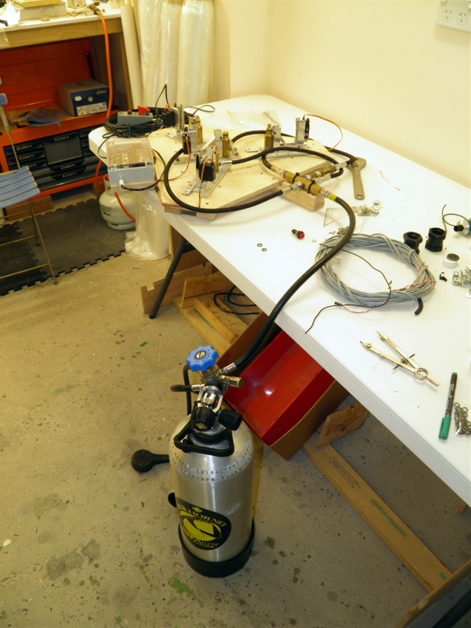
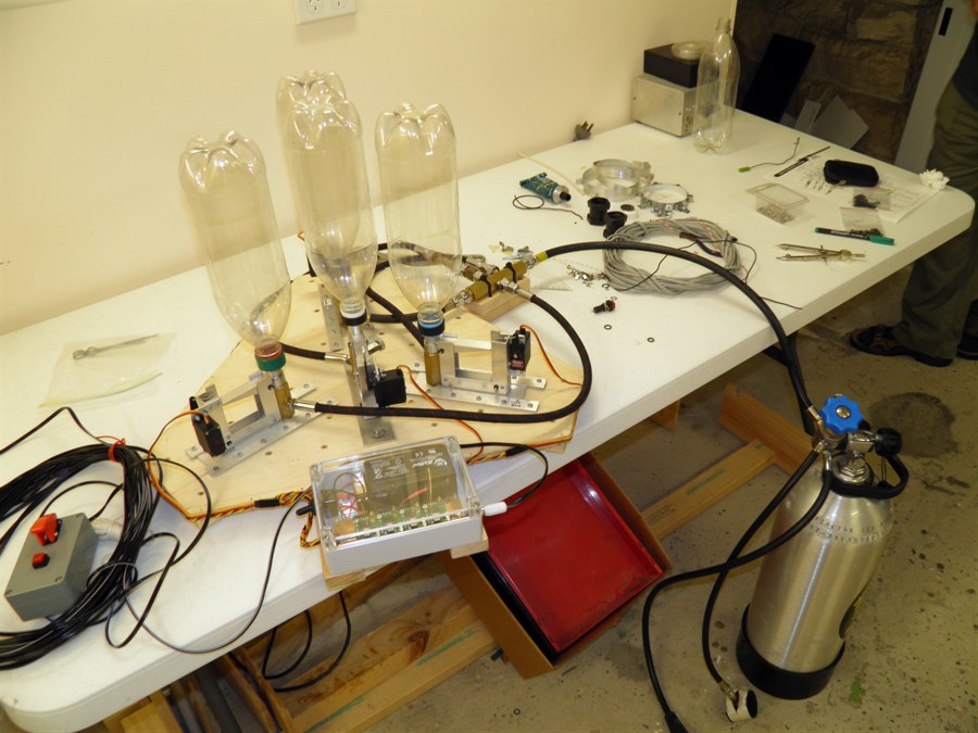
16 April 2014
- We checked and replaced some of the o-rings in
the air
distribution manifold and hoses. We also
tested the non-return
valve to make sure the main stage was
holding pressure when the boosters were
emptied. We then tested the pressure release
valve on the main nozzle seat to make sure
we can safe the main stage in case of an
abort. We tested the launcher in the front
yard at 10psi, 20psi and 30psi to make sure
everything was sealed and the nozzle release
would all happen at the same time.
We then disassembled the entire launcher
so we could paint it with water proof
acrylic paint.
Testing for leaks
Testing first releases at night
Disassembling for painting
18 April 2014
- We painted the base and legs today with a
couple of coats. We also replaced the short
hose going to one of the booster nozzles
with a more flexible one that allows it to
slide easier. The hoses we are using can be
cut to length and then the end fittings can
be re-connected.
19 April 2014
- We finished painting the third coat today.
We also reprogrammed the STIIs to have a
shorter arm delay and adjusted the timing to
5ms increments.
3 fresh coats of paint that will
hopefully seal the wood
21 April 2014
- With the paint dry we re-assembled launcher.
We also added o-rings between the servo horn
and the servo body to prevent water from
entering them at that point. Thank you to OFlorin
for this great suggestion. We coated the
o-rings in silicone grease to prevent them
from sticking.
We took the launcher to the local oval so
we could do higher pressure tests and also
look at the synchronization of the releases.
We adjusted the timing to get
reasonable results. For one of the tests we
delayed the main stage release to see what
the timing would be like to make sure the
boosters are released before the main stage.
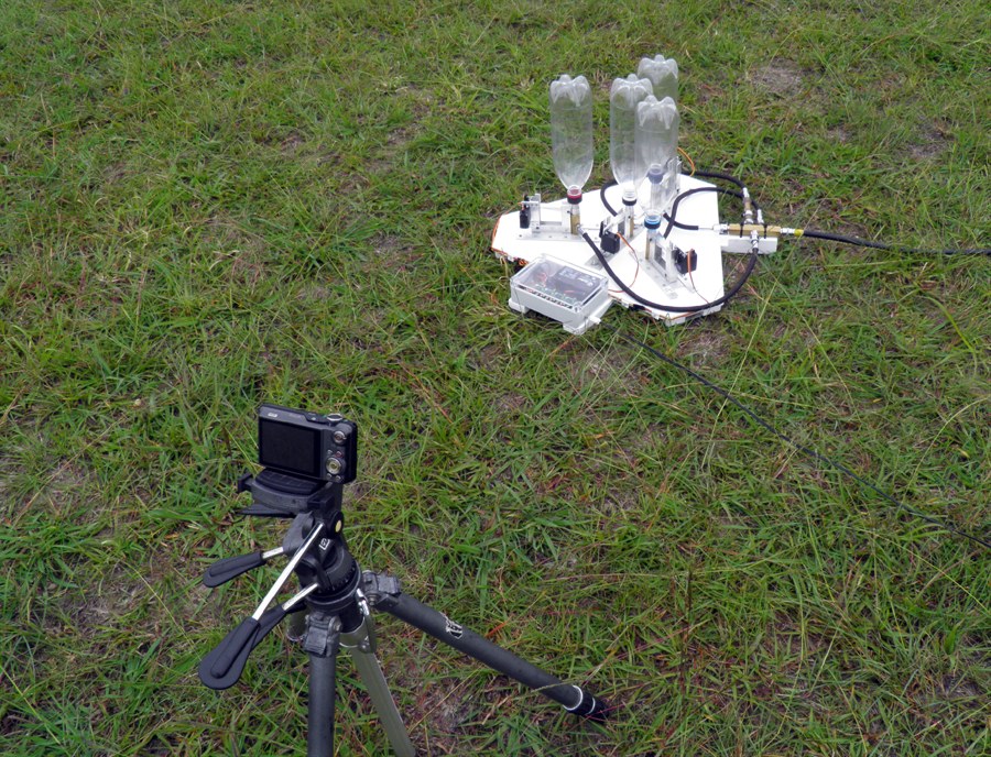
Paul helping set up the high
speed camera
GoPro filming at 240fps.
25 April 2014
- After the last set of tests we noticed
that 5ms step increments didn't quite give
us the fine timing control that we wanted so
we reprogrammed the STIIs to give us 2ms
field adjustable timing. This gives us a
range of 24ms to choose from. We also made
up a short removable fill tube so we could
test it with some water.
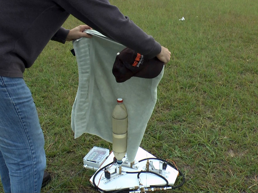
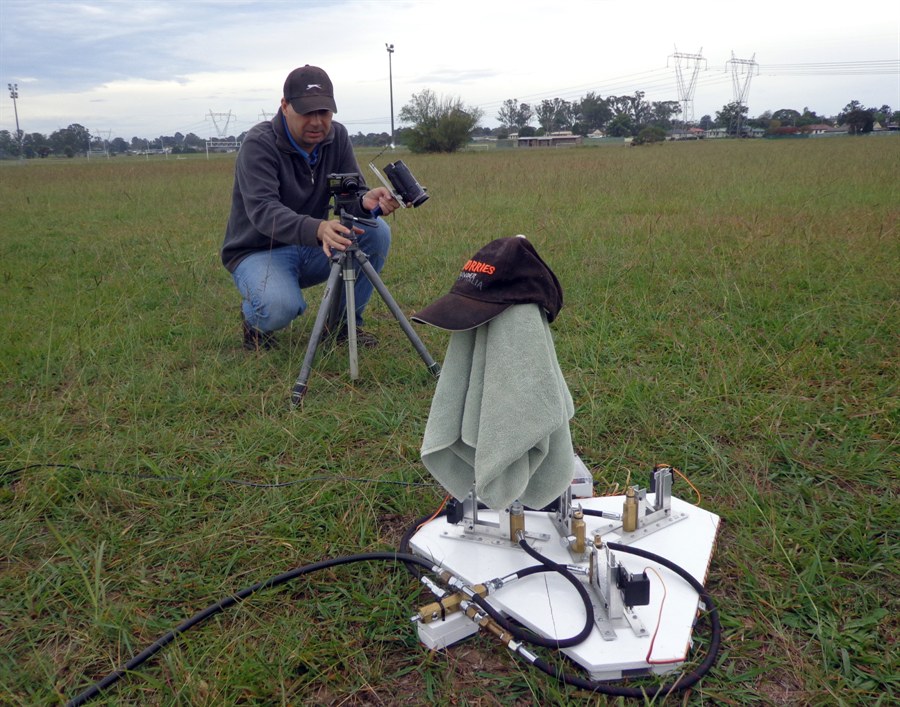
26 April 2014
- We took the launcher to Whalan Reserve
today to do three tests. Re-sync the
launcher using the new finer control, do one
test with water and a fill tube and test
each of the release heads at 200psi. All the
tests went well and we can now start
focusing on the rocket.
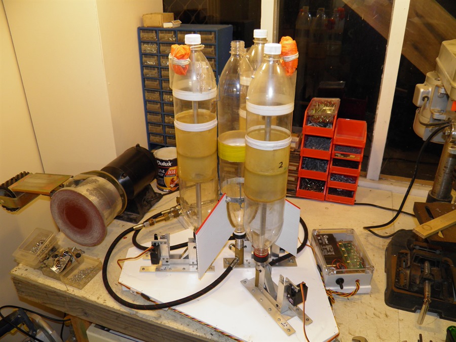
Ready for sync test
Adding drag and weight to
reinforced bottle
Ready to launch
No worries
200psi air only test
Testing with fill tube and water
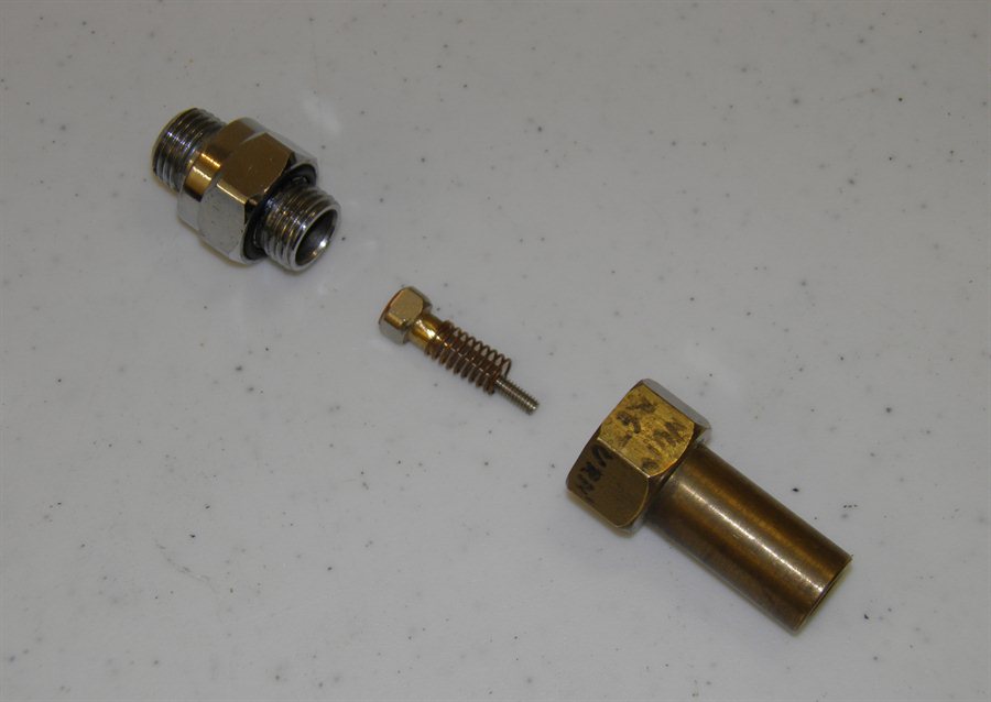
20 May 2014 - After some thought
we decided to make the fill tubes removable
so that we could use different size ones
depending on the size of the boosters. So we
made up extensions to fit on the nozzle
seats with a thread that allows us to screw
a fill tube over the top. This also makes it
easier to transport the whole launcher. We
just epoxied the extensions onto the nozzle
seats. Dad then cut threads into the
aluminium tubes which make up the fill
tubes. We can make easily make up a set of
these for the different booster sizes.
Thread adaptors for nozzle seats
Threaded fill tubes that screw
onto the adaptors
Thread adaptors fitted to
launcher
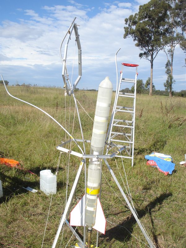
26 May 2014 - To move to the next
stage of testing we decided to launch a
small low pressure rocket from the launcher
to see how well the synchronization works.
We used the same booster retaining ring as
we used on the Axion G4 tests. For this we had to
attach a thrust ring to the main stage. This
was achieved by gluing 2 PET sleeves to the
main stage with PL premium. The rest of the
rocket was normal as were the old Gluon
boosters.
Thrust ring glued to the main
stage
Fill tubes on launcher
Boosters fitted on launcher
30 May 2014 - Final prep for the
launch. We attached the narrow guide rail to
the launcher that allows it to fit between
the fins and the boosters. We also further
water proofed the launcher by taping up the
servo motors and any wire connectors that
were exposed to the water streams.
Final prep the night before
launch
31 May 2014 - Test launch day.
Today we launched the Axion II rocket with
Gluon boosters successfully 3 times from the
launcher. See Day 146 for a full flight
report.
21st September 2014 - Made up the
booster clamps today. We are using the
smaller 90mm main stage clamp from the
previous tests. We test fitted it to the
rocket to see if everything remains
aligned.
23rd September 2014 - We attached
the booster thrust ring today with the
24 hour epoxy. The booster was masked
off with electrical tape to give the
clamp a clean surface to sit on. We held
the thrust ring in with a piece of wire.
The thrust ring is made from an old
reinforced 2L bottle that we cut up.
Each thrust ring has 2 layers of the
reinforcing.
24th September 2014 - Test
fitting the booster clamps against the
thrust rings and doing final alignments.
We also made up the top booster clamps
with only a single pin. We decided to
reuse the fairing from the previous test
rocket as it already had the loops
attached.
30th September 2014 - We attached
the parachute deployment mechanisms to
the boosters today. These are only
temporary for this test as they will be
mounted between the booster segments on
the final booster. We attached small
sections of PET plastic to the side of
the bottle and these were held by glass
strapping tape wrapped all the way
around as normal tape does not stick to
the fiberglass. We attached the sections
so we could attach the parachute doors
to them with tape. We also attached PET
plastic steps underneath the parachutes
so they would not slip out during boost.
5th October 2014 - Trip to
Mulalley launch site to test boosters
with Axion G5. See
Day 152 for full details.
19 December
2014 - Tested 3 booster segments to
220psi and cut out the rest of the booster deployment
mechanisms.
20 December 2014 - Finished deployment
mechanism housings for G2 boosters and attached
them to the fairings. Made the top main stage
clamp and made fill tube extension tubes.
27 December 2014 - We glued the
first of the thrust ring layers to the
main pressure chamber.
28 December 2014 - We glued the
second of the thrust ring layers to the
pressure chamber.
1
January 2015 - Machined up fill tube
extensions from brass 3x. Glued
extensions into the fill tubes.
17 February 2015
- We attached small
rail buttons to the rocket to go on the
narrow guide rail. We also attached the
parachutes to boosters. Finally we also
did a pressure leak test on the booster
nozzles as we've had problems with them
in the past.
18 February
2015 - We re-attached the fins to
the main stage. The fins had to have
sections cut out of them to fit over the
thrust ring and booster clamp. We also
prepared a second set of fins in case a
booster again broke a fin off on
deployment. We also attached the booster deployment wires
to the main stage. These wires are used
to deploy the parachutes on the
boosters.
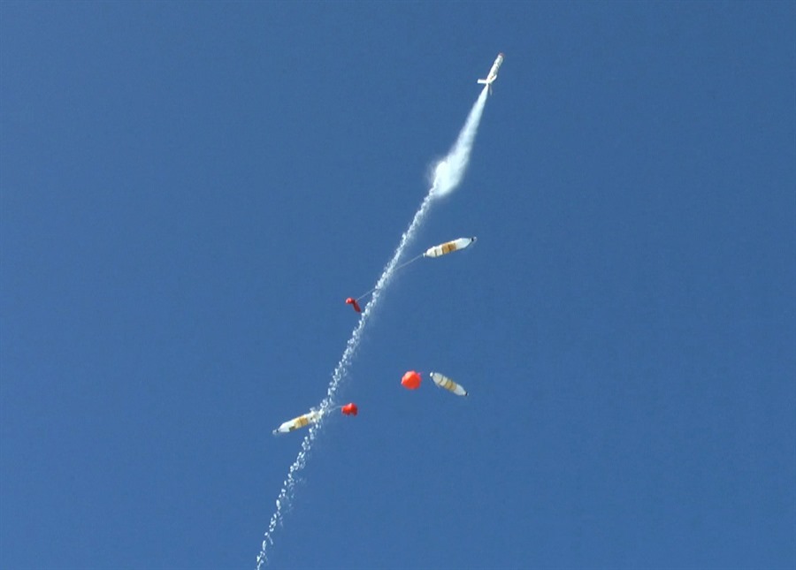
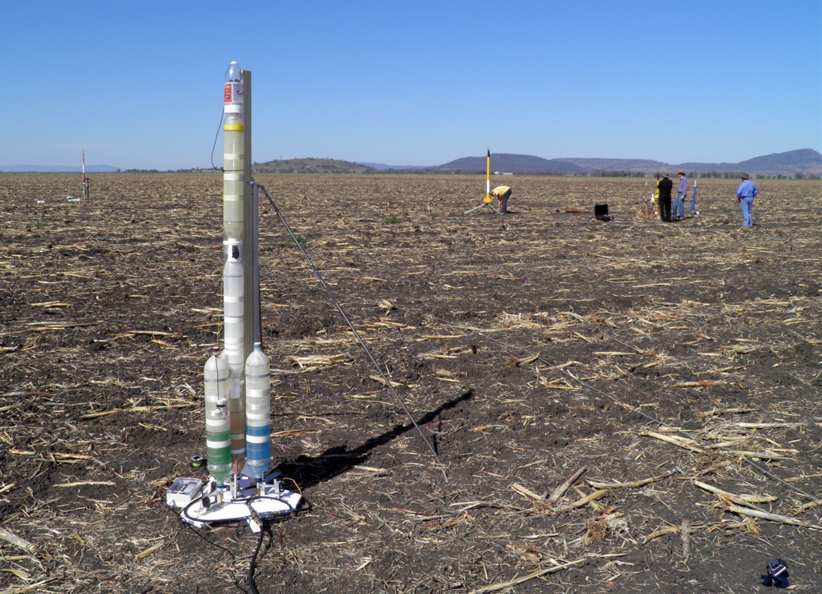
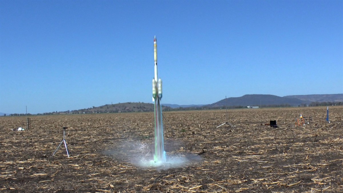
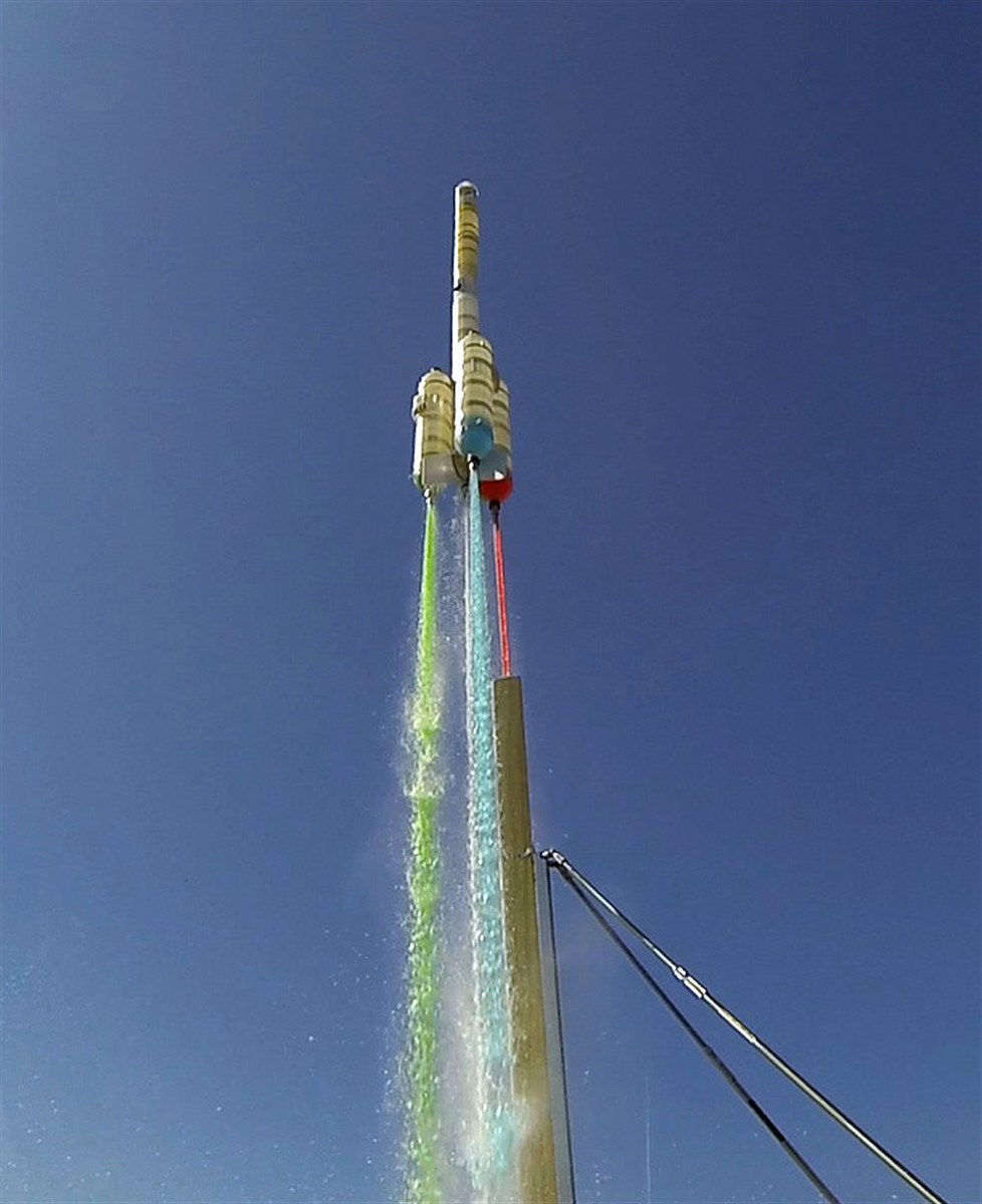
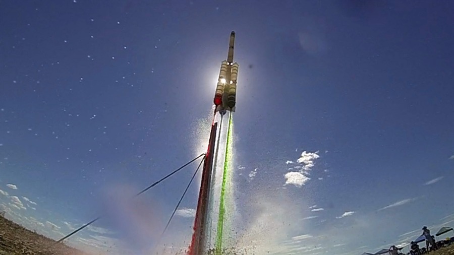
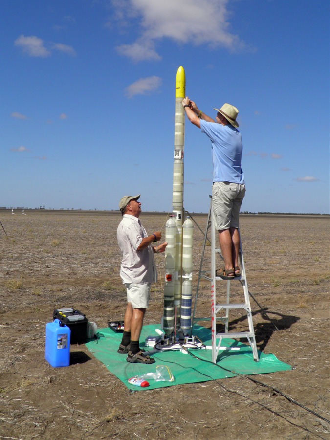
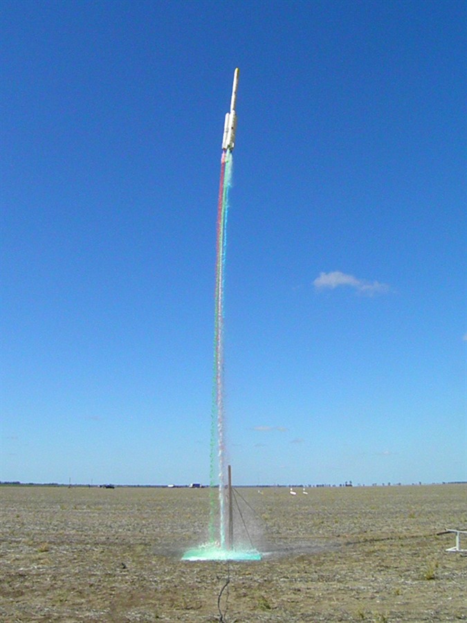
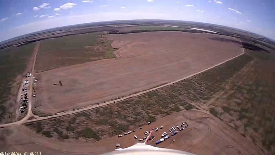
12 March 2015
- Flight day. The Polaron G2 - Phase
2 has been successfully flown at Westmar
a couple of times.
Please see day 157 for a full flight
report.