Video describing the operation of the FC.
Normal Mode
To enter normal
mode, simply turn the FC on. Before delving deeper into how
to configure all the FC parameters let�s have a look at a
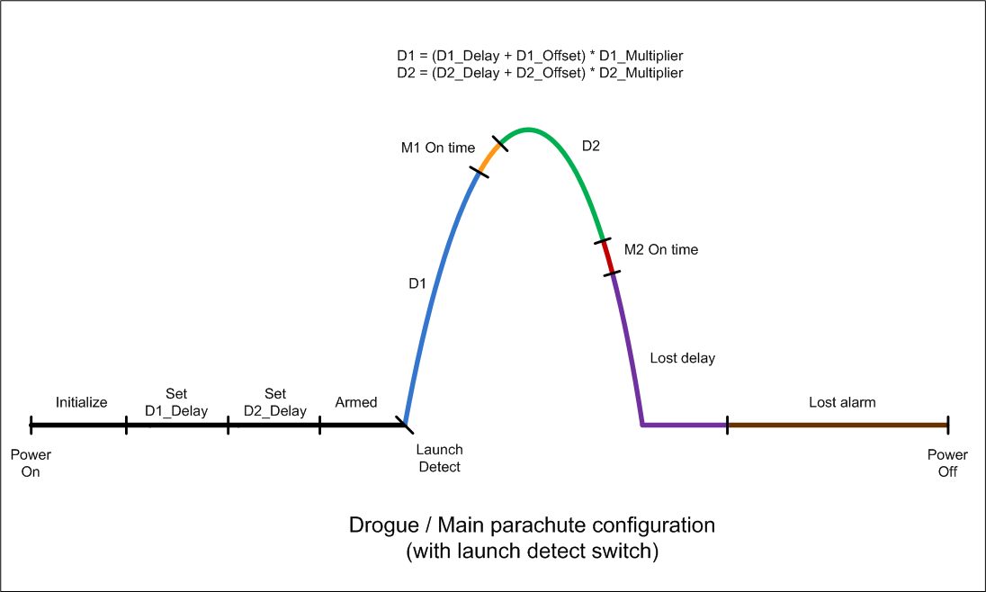
typical flight profile (Figure 2)
and see how it behaves. The flight profile is broken up into
a number of different phases. The 15 configuration
parameters affect what happens in each of these phases.
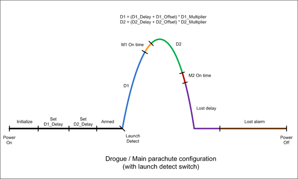
Figure 2
- Typical Flight Profile Operational Phases
Operational Phases
- Initialize
� The FC sets both
servomotors to their preset positions (Position 1) and
reloads all the parameters to the previously stored
values.
Display shows:

- Set D1_Delay
(�2.�) � In this phase the
user can change the D1_delay parameter by repeatedly
pressing the PGM button. Any changes made are
automatically stored in the EEPROM. See the Configure
Mode section for
explanation of the D1_Delay parameter.
Display alternates between:  <-- -->

Pressing the ARM button moves to the next
phase.
- Set D2_Delay
(�5.�) � In this phase the
user can change the D2 Delay parameter by
repeatedly pressing the PGM button. Any changes made are
automatically stored in the EEPROM. See the Configure
Mode section for
explanation of the D2 Delay parameter.
Display alternates between:
 <-- -->

Pressing the
ARM button again arms the rocket.
- Armed
� The FC waits for the rocket to
launch. Typically one would arm the rocket first and
then pressurise it. While in this phase the rocket beeps
once a second and toggles the display showing the values
set for the D1 Delay and D2 Delay
parameters. This allows for quick visual and audible
check to see if the rocket is ready for launch.
Display alternates between:
<-- -->
A trigger will cause the rocket to go to the next phase.
- D1
� Typically the first delay (D1)
is activated at the time of launch. D1 usually operates
in the ascent stage of the rocket flight. When this
period expires the FC goes to the next phase.
Display shows:

- M1 On Time
� At the end of D1
servomotor M1 moves from position 1 to position 2. The
amount of time it spends doing that is set through the
M1 On Time parameter. The servo remains in this
position until power is turned off. This is the time
that a parachute or the next stage is released.
Display shows:

At the completion of the servo
repositioning the FC moves to the D2 phase.
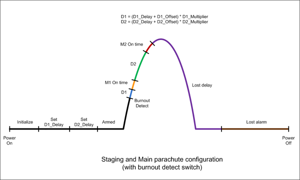
- D2
� The FC waits a second period of
time before the second servomotor is activated.
Display shows:

At the conclusion of the D2 delay the FC
switches to the next phase.
- M2 On Time �
Servo M2 moves from
position 1 to position 2. The amount of time it spends
doing that is set through the M2 On Time
parameter. The servo remains in this position until
power is turned off.
Display shows:

When the motor
finishes moving the FC switches to the lost delay phase.
- Lost Delay �
If enabled, the FC waits for another period of time
before starting the lost rocket alarm. Typically the
rocket is found by the time the alarm sounds and power
is turned off. The period can be set from 0 minutes to
31 minutes.
Display shows:

- Lost Alarm �
When the Lost Delay period expires, the alarm
starts sounding and continues indefinitely until either
power is turned off or the batteries are run flat.
Display shows:

Flight Profiles
Following are a few
different flight profiles that can be configured with the FC.
Please refer to the examples section for more details on
these:
- Single stage
with launch detect
- Single stage
with burnout detect
- Two stage �
Staging and parachute with launch detect
- Two stage �
Staging and parachute with burnout detect
- Dual Parachute
with launch detect
- Dual Parachute
with burnout detect
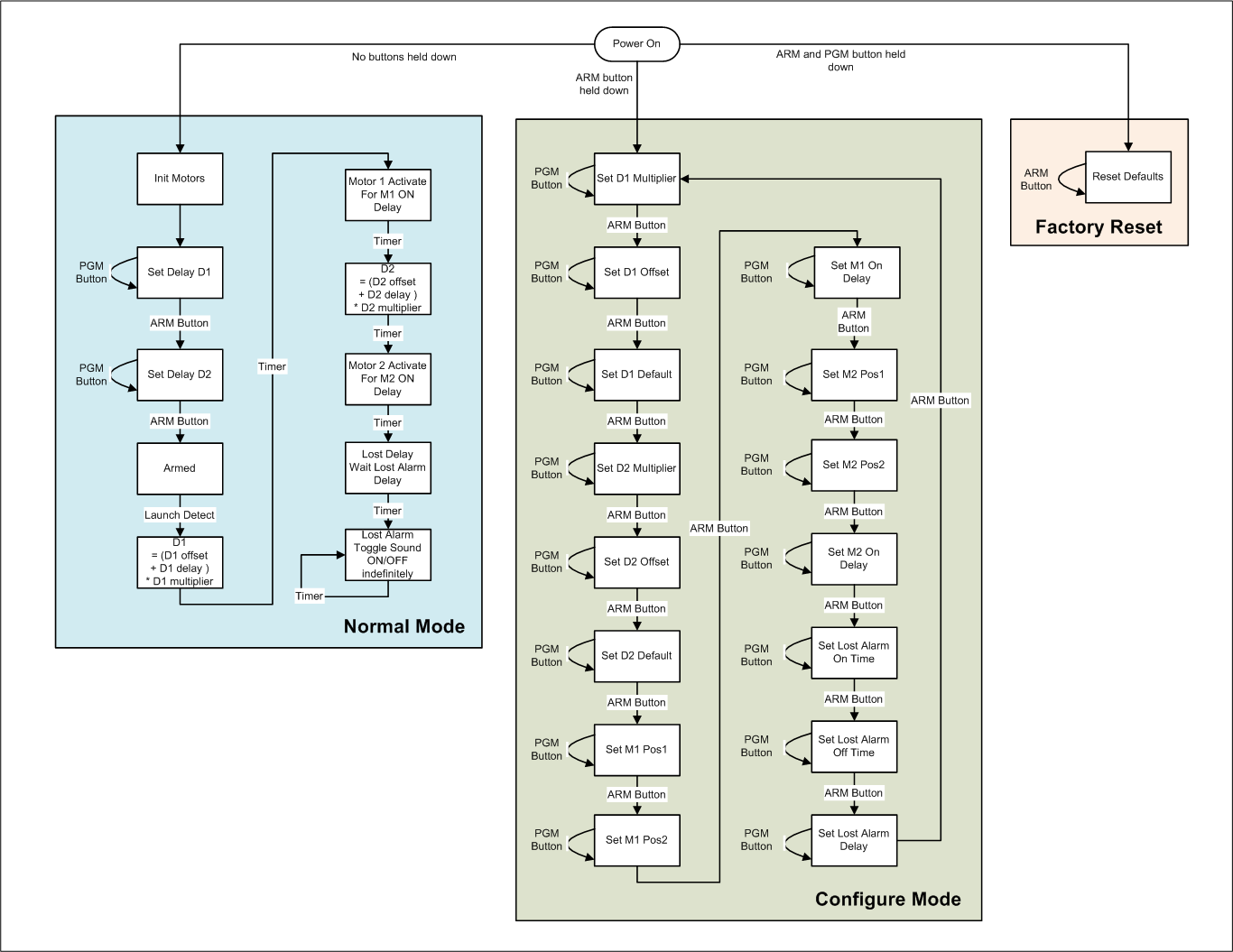
Configure Mode
In the configure mode the user can
cycle through all the parameters and change their values.
All values are automatically stored in the EEPROM. Table 1
describes each of the parameters and the range of values
that can be set for each. Table 2
describes the values themselves. To avoid confusion a
parameter name on the display is designated with a �.�
(decimal point) and the value belonging to the parameter
does not have the decimal point.
Since the values can range 0 to 31,
and there is only a single 7 segment display, alpha-numeric
characters (0 � 9, and A � V) are used to display all
values.
To enter configure
mode and change the parameters do the following:
- Make sure power
switch is set to OFF.
- Hold down only
the ARM button and set the power switch to ON.
The �S� symbol appears on the screen indicating you are
in �Set� or configure mode
- Press the ARM
button repeatedly to cycle through the parameters.
- Press the PGM
button repeatedly to cycle through the parameter values.
- When finished
changing the parameters switch the power switch to OFF.
|
Parameterer |
Mnemonic |
Default |
Range |
Display
|
Description
|
|
D1
Multiplier |
D1Mul |
4 |
[0 � 7] |
 |
0 = 0.01 sec
/ step
1 = 0.02 sec
/ step
2 = 0.05 sec
/ step
3 = 0.1 sec
/ step
4 = 0.2 sec
/ step
5 = 0.5 sec
/ step
6 = 1.0 sec
/ step
7 = 2.0 sec
/ step |
|
D1 Offset |
D1Off |
F |
[0� V] |
 |
D1 = (D1Dly
+ D1Off) * D1Mul |
|
D1 Delay |
D1Dly |
0 |
[0� V] |
|
D1 = (D1Dly
+ D1Off) * D1Mul |
|
D2
Multiplier |
D2Mul |
4 |
[0� 7] |
 |
0 = 0.01 sec
/ step
1 = 0.02 sec
/ step
2 = 0.05 sec
/ step
3 = 0.1 sec
/ step
4 = 0.2 sec
/ step
5 = 0.5 sec
/ step
6 = 1.0 sec
/ step
7 = 2.0 sec
/ step |
|
D2 Offset |
D2Off |
0 |
[0� V] |
 |
D2 = (D2Dly
+ D2Off) * D2Mul |
|
D2 Delay |
D2Dly |
0 |
[0� V] |
|
D2 = (D2Dly
+ D2Off) * D2Mul |
|
M1 Position
1 |
M1P1 |
0 |
[0� V] |
 |
Motor 1
Position 1. (prior to launch) |
|
M1 Position
2 |
M1P2 |
V |
[0� V] |
 |
Motor 1
Position 2 (after delay D1) |
|
M1 On Time |
M1On |
F
(2.4 sec) |
[0� V] |
 |
0.16 sec /
step |
|
M2 Position
1 |
M2P1 |
0 |
[0� V] |
 |
Motor 2
Position 1 (prior to launch) |
|
M2 Position
2 |
M2P2 |
V |
[0� V] |
 |
Motor 2
Position 2 (after delay D2) |
|
M2 On Time |
M2On |
F
(2.4 sec) |
[0� V] |
 |
0.16 sec /
step |
|
Lost On Time |
LOn |
1 |
[0� V] |
 |
0.25 sec /
step |
|
Lost Off
Time |
LOff |
4 |
[0� V] |
 |
0.25 sec /
step |
|
Lost Delay |
LDly |
5
(5min) |
[0� V] |
 |
minute /
step
|
Table 1
- Configurable Parameters
|
Value |
Index |
Displayed as
|
|
Value |
Index |
Displayed as
|
|
Value |
Index |
Displayed as
|
|
0 |
0 |
 |
|
B |
11 |
 |
|
M |
22 |
 |
|
1 |
1 |
 |
|
C |
12 |
|
|
N |
23 |
 |
|
2 |
2 |
 |
|
D |
13 |
 |
|
O |
24 |
 |
|
3 |
3 |
 |
|
E |
14 |
 |
|
P |
25 |
 |
|
4 |
4 |
 |
|
F |
15 |
 |
|
Q |
26 |
 |
|
5 |
5 |
 |
|
G |
16 |
 |
|
R |
27 |
 |
|
6 |
6 |
 |
|
H |
17 |
 |
|
S |
28 |
 |
|
7 |
7 |
|
|
I |
18 |
 |
|
T |
29 |
 |
|
8 |
8 |
 |
|
J |
19 |
 |
|
U |
30 |
 |
|
9 |
9 |
 |
|
K |
20 |
 |
|
V |
31 |
 |
|
A |
10 |
 |
|
L |
21 |
 |
|
|
|
|
Table 2
- Parameter Values
Functionality
Timing
The two main timing delays D1 and D2
are configured through 3 parameters each. The first of these
parameters is the multiplier. The multiplier defines the
�granularity� of the timing of the other two parameters. The
multiplier can be set to increment the delays in steps as
low as 0.01s or as high as 2s. This allows the timing delays
to be set anywhere from 0.01seconds to 128 seconds depending
on the requirement. Both D1 and D2 are configured in the
same way.
The formula below gives the delay
period:
Dx = (DxDelay + DxOffset)
* DxMultiplier
Where x = 1 for delay D1 and
x = 2 for delay D2.
The second parameter is the Offset.
The Offset allows you to set a zero point, or minimum
time for the delay. The last parameter is the variable delay
(DxDelay). This delay can be varied while in the
normal mode and is intended to be adjusted between launches
to finetune the recovery system release time or if the
pressure, water volume or nozzle size change. Both the
offset and delay can be set to one of 32 values.
Short delays are useful for staging
rockets, and long delays are useful for opening main
parachutes late into the flight.
Timing Periods
Table 3
lists the minimum and maximum values that each specific
phase can be configured to.
|
Delay |
Min |
Max |
|
D1 |
0.01 sec |
128 seconds |
|
M1On |
0.16 sec |
5.12 seconds |
|
D2 |
0.01 sec |
128 seconds |
|
M2On |
0.16 sec |
5.12 seconds |
|
Lost
Delay |
0 sec |
32 minutes |
Table 3
- Delay Ranges
Each of the servomotors has two
configurable positions Position 1 and Position 2.
Position 1 is the position prior to launch. This
would typically be the latched position of the recovery
system. Position 2 is the position of the servomotor
after the expiry of the appropriate period. The motors
remain at their Position 2 position until power is
turned off.
RC servomotors are positioned using a
specific pulse train on their control line. The FC generates
this pulse train for only a short period of time determined
by the M1 On Time or M2 On Time parameters.
This allows battery power to be conserved when the motors
are not required to move. The On Time should be
adjusted in such a way that the motor has enough time to
move from one position to the other. Sometimes this needs to
be adjusted depending on the motor used or if there is a
load on the motor and it takes longer.
The full range of movement of each
servo is divided into 32 steps. This means a servomotor that
normally has a 90 degree range of movement will be able to
be positioned with an accuracy of 2.8 degrees, while a servo
that has a 200 degree range of movement can be positioned
with an accuracy of 6.25 degrees.
The positions are made configurable to
allow the servomotors to be mounted inside the deployment
system in any orientation. Sometimes clockwise operation is
needed and sometime anti-clockwise is required.
The positions can also be adjusted
between flights in the Configure Mode if something
becomes misaligned or stretched in the deployment system and
the servomotor positions need to be updated to compensate.
The FC can use the built in buzzer to
sound an alarm after a delay to assist the user to locate
the rocket if it is lost in tall grass or bushes.
There are 3 configuration settings
associated with the alarm. The first is the number of
minutes it takes before the alarm is activated (Lost
Delay). This is useful for two reasons. Firstly it
allows the FC to conserve the battery since in most
instances the rocket will be found before the alarm needs to
sound. Secondly it allows the FC to remain quiet in flight
when used in combination with a video camera that is also
recording audio.
The other two parameters are used to
configure the sound duration during the alarm phase. Setting
the Lost On Time to a short beep and the Lost Off
Time to a long period allows the FC to conserve power,
but for more noisy environments the alarm can be set to
produce noise more frequently at the expense of power
consumption.
Setting the Lost On Time to
zero allows the lost alarm functionality to be switched off
altogether.
Most of the fun only happens after the
FC is triggered in the Armed phase. Triggering can be
achieved a number of different ways depending on the rocket
design. Some examples include:
- Launch
detect � This is typically
achieved using a G or acceleration switch. Triggering
occurs as soon as the rocket leaves the launch pad.
Another variation to this is a set of contacts that are
closed and an insulator is removed from between them
during launch. The insulator is usually attached so it
stays with the launcher.
- Burnout
detect - This technique
uses a pressure switch to detect when the pressure
inside the rocket has reached atmospheric pressure, or
some preset value. This is useful for staging rockets.
This allows the rocket to deploy the second stage at the
correct time regardless of how much pressure or water
was used in the booster.
- Negative G
detect � This is another
technique used to detect when the rocket has stopped
producing thrust and the rocket starts to slow down. An
inverted mercury switch can be used here where the
mercury floats upwards to make contact as drag continues
to slow the rocket down after burnout. Negative Gs
happen shortly after burnout.
We�ll leave it up to the rocket
builder to come up with their own way to trigger the FC. The
FC can have a G-switch fitted directly to the PCB, but the
FC also provides a connector for external triggers inputs.
Following are a number of examples
demonstrating how to configure the FC for various scenarios.
You want to use a single parachute on
a simple rocket. You want the parachute to deploy no earlier
than 3 seconds, but you want to be able to increase that
time in 0.2 second increments on subsequent flights as you
change the amount of water or pressure. You also don�t want
to use the lost alarm functionality. You will also be using
the built in G-switch.
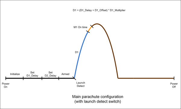
Figure 3 - Simple rocket with single
parachute scenario
This is how you would configure the
computer:
We select our Delay1 Multiplier
to be 0.2 seconds (value = 4) (see table Table 1)
We set the Delay 1 Offset to be
3 seconds (value = 3 seconds / 0.2 = 15 = F)
During normal operation you can then
change the �2.� parameter in 0.2 second increments
meaning you can increase the time from 3 seconds to a
maximum
D1 = (15 + 31) x 0.2 = 9.2 seconds.
Motor M1 is set for full range
movement by setting �6.� to 0 and �7.� to V.
If the servo was to move in the other direction the two
values would be reversed. The servomotor will be on for 2.4
seconds. This is set by parameter �8.� (value = 2.4 /
0.16 = 15 = F)
We set the �C.� parameter to 0
to turn off the lost alarm.
|
|
D1 |
D2 |
M1 |
|
D1Mul |
D1Off |
D1Dly |
D2Mul |
D2Off |
D2Dly |
M1P1 |
M1P2 |
M1On |
Param
|
|
|
|
|
|
|
|
|
|
|
Value |
0.2sec |
|
0 sec |
|
|
|
0 |
32 |
2.4sec |
|
|
|
|
M2 |
Lost |
|
|
M2P1 |
M2P2 |
M2On |
LOn |
LOff |
LDly |
|
|
Param |
|
|
|
|
|
|
|
Value |
|
|
|
|
|
|
Now if the rocket
will fly with the same setup on every launch, all you have
to do for each launch is turn on the FC and press the ARM
button twice and the rocket is ready to go. This makes it
very simple to use once configured.
Say you have a more advance rocket
that wants to deploy a drogue parachute at apogee and then
the main parachute some time later when it has had a chance
to descend some way. This technique is often employed to
prevent large parachutes from being opened at high speeds as
well as to stop the rocket drifting too far in windy
conditions.
You also want to use the lost alarm
functionality as you are flying in wooded terrain.
A simulation of the rocket predicts
that it will reach apogee after 7.25 seconds. Because this
is the first flight you will want to have some control over
the 1st delay either side of the 7.25 seconds on
subsequent launches.
Using drogue parachute descent rate
calculations you decide that the main parachute should
deploy 22 seconds after apogee.
This is how you would configure the
computer:
Calculate D1
Here we can choose say the 0.2sec or
0.5sec step value for the D1 multiplier. I will
choose the 0.2 second multiplier (�0.� Set to 4) so
that we can fine tune the deployment. I am going to allow
the D1 delay to be adjustable from 6 seconds upwards.
D1 Offset (�1.�) is set to 6 / 0.2 = 30 = U.
If I had chosen to use the 0.5second
multiplier then the D1 offset parameter would have
been set to 6 / 0.5 = 12 = C.
We now need to set the D1 delay
parameter (�2.�) to bring up the total time as close
to the 7.25 seconds as possible. Since we chose the 0.2s
multiplier, we need to set D1 delay to 7.25s � 6s =
1.25s. Now 1.25s / 0.2 = 6.25. We pick the closest integral
value to 6.25 which is 6. So this means the deploy time
using the delay formula becomes:
D1 = (30 + 6) * 0.2 = 7.2seconds
which is close enough to the required 7.25 seconds. This
setting allows us to chance the delay in Normal Mode
from 6 seconds to 12.4 seconds.
Calculate D2
D2 is less critical since the
22seconds after apogee is only a rough estimate. For this
delay we may choose the 1 second or 2 second multiplier.
I�ll choose the 1 second multiplier. (�3.� = 6)
Let�s say we want to set a minimum
time of 14 seconds and vary the time up from there. D2
offset would be set to 14 x 1 = 14 = E. And to get to 22
seconds we set D2 delay parameter to 22 � 14 = 8. This gives
us the ability to vary the D2 period from 14 seconds to 46
seconds in the Normal Mode.
Set M1 and M2
Because of the deployment system
configuration we need to set the M1 servomotor to turn
clockwise and the M2 servomotor to turn anticlockwise when
activated. We set the positions as appropriate for the
deployment system. In this example they are just set to full
range. The On Time for both servos requires 1 second.
See the values. See table below.
Set Lost Alarm
We choose to set the alarm for 5
minutes after main parachute deployment, and we want the
sound to beep for 1 second and stay quiet for 3 seconds.
Parameter �E.� sets the delay in minutes, so we set
it to 5. The sound on time and off time are given in
0.25second increments so we set �C.� to 4 (1sec/0.25
= 4) and the �d.� parameter to C (3sec/0.25 = 12 = C)
|
|
D1 |
D2 |
M1 |
|
D1Mul |
D1Off |
D1Dly |
D2Mul |
D2Off |
D2Dly |
M1P1 |
M1P2 |
M1On |
Param
|
|
|
|
|
|
|
|
|
|
|
Value |
0.2sec |
|
1.2sec |
1 sec |
14 sec |
8 sec |
0 |
32 |
.96sec |
|
|
|
|
M2 |
Lost |
|
|
M2P1 |
M2P2 |
M2On |
LOn |
LOff |
Ldly |
|
|
Param |
|
|
|
|
|
|
|
Value |
32 |
0 |
.96 |
1 sec |
3 sec |
1 min |
Now if the rocket will fly with the
same setup on every launch, all you have to do for each
launch is turn on the FC and press the ARM button twice and
the rocket is ready to go.
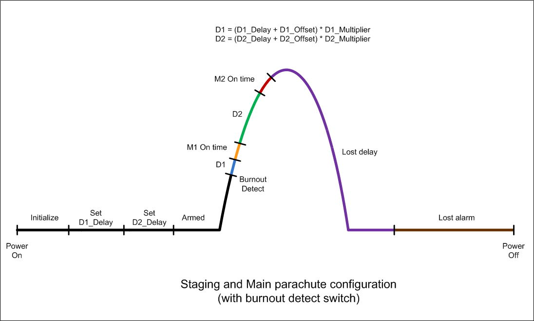
In this scenario the FC is fitted to
the booster of a 2-stage rocket and will be used for
initiating the staging of the next stage and at a time later
for opening a parachute on the booster. The ideal time to
release an upper stage is when the booster is travelling at
its fastest which happens right around burnout. It is also
the worst time to deploy a parachute since it could be
ripped off.
The external trigger this time is
based on a pressure switch that activates when the pressure
inside the rocket drops to 10psi above atmospheric pressure.
This means that a short time later the rocket will be
travelling the fastest as the pressure drops to 0.
This is how you would configure the
FC:
Let�s assume that the time between the
sensing of the pressure drop to the time that the second
stage should be released is only 30ms. We need to set the
D1 multiplier to 0.01s = 0. We set the D1 Offset
to 3 x 0.01s = 30ms = 3. We set D1 delay to 0.
M1 and M2 positions and On Times are
configured as in the previous example. And the lost alarm
functionality is turned off.
In this example we set the delay to
parachute opening to be 2 seconds after staging. The D2
Multiplier is set to 0.5s and the D2 offset is
set to 4 giving us 2 seconds. We can then vary that in half
second increments.
|
|
D1 |
D2 |
M1 |
|
D1Mul |
D1Off |
D1Dly |
D2Mul |
D2Off |
D2Dly |
M1P1 |
M1P2 |
M1On |
Param
|
|
|
|
|
|
|
|
|
|
|
Value |
0.01s |
|
0sec |
0.5s |
2 sec |
0 sec |
|
|
|
|
|
|
|
M2 |
Lost |
|
|
M2P1 |
M2P2 |
M2On |
LOn |
LOff |
LDly |
|
|
Param |
|
|
|
|
|
|
|
Value |
|
|
|
|
|
|
Now if the rocket will fly with the
same setup on every launch, all you have to do for each
launch is turn on the FC and press the ARM button twice and
the rocket is ready to go.
To reset the configurable parameters
back to the default factory settings do the following:
- Make sure power switch is set to
OFF
- Hold the PGM and ARM buttons down
at the same time and turn the power switch to ON.
- The �r� character will be
displayed.
- Press the ARM button once more to
confirm the reset.
- After the beep, turn the power
switch to OFF.
The default factory settings are set
up for a typical single stage 2L water rocket.
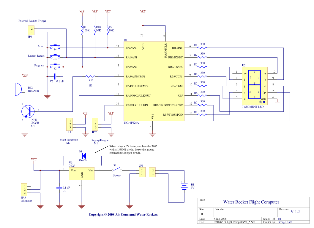
Hardware
The circuit diagram for version 1.5 is
shown in Figure 4. Central to
the design is the PIC16F628A microcontroller from Microchip.
The on-board oscillator is used to reduce the external
component count.
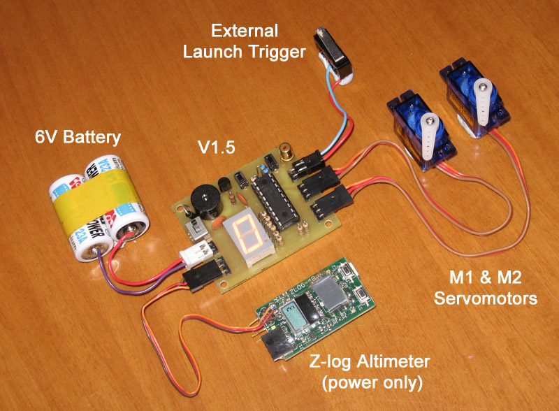
A power connector JP3 is provided that
allows an altimeter such as the Z-log to be connected
directly to the power supply. This connector will be used in
future versions as the auxiliary device connector.