This section describes the details of the water rocket flight
computer (FC) as designed by the Air Command team.
The purpose
of the FC is to co-ordinate various events during the flight of
a water rocket. One of its responsibilities is to deploy the
parachute at the desired time.
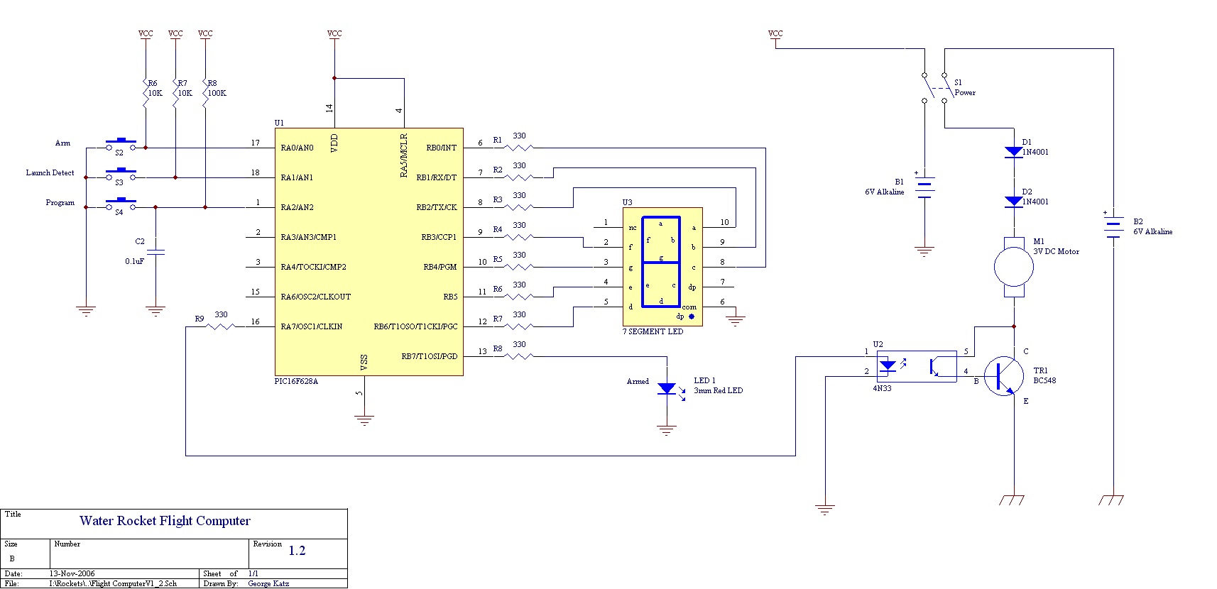
Version 1.2
V1.2 Circuit diagram
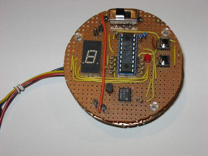
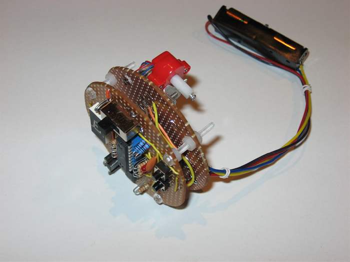
FC Prototype (front)
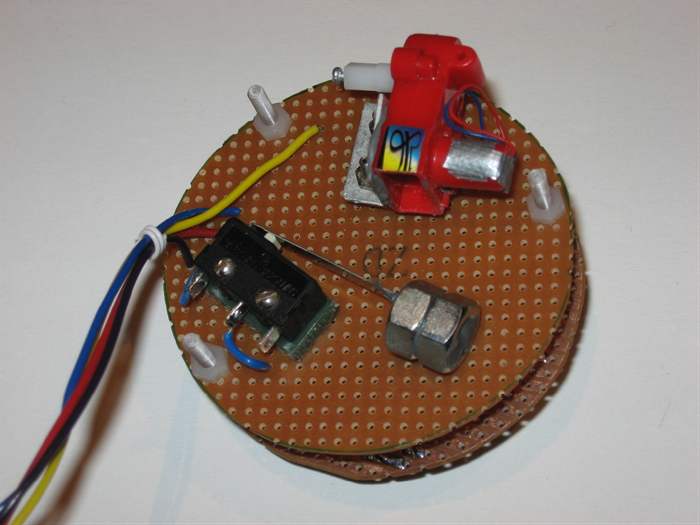
FC Prototype (back) Motor & gearbox at the
top and launch detect switch at the bottom
FC assembled
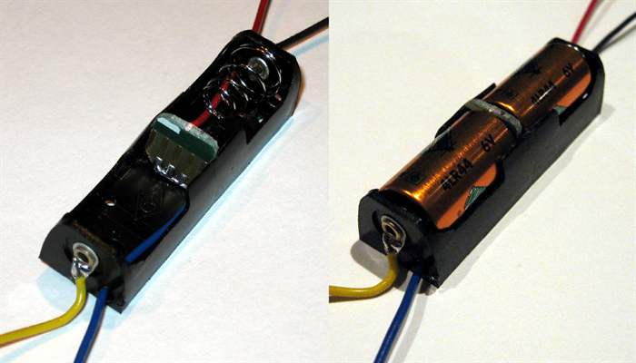
Power supply.
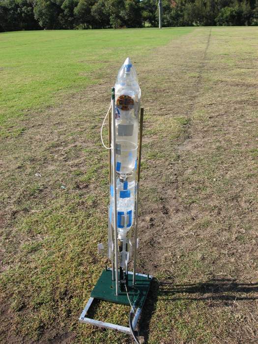
FC ready for its maiden flight.
Version 1.2 of the FC was successfully flight tested on 11th
November 2006 with 100% parachute deployment reliability over
the 5 missions flown that day.
Update: As of 3rd
February 2007 the FC had flown 17 missions.
16 successful deploys
1 failed deploy. - Suspect grain of sand in the motor gearbox.
This version of the FC was
intended to test the ability of the system to function at water
rocket type G forces and to test the entire system from launch
detect, parachute deployment to the recovery phase. Future
versions of this FC will have more capability such as apogee
detection for parachute deployment and many other experiments.
Following is a detailed description of the FC V1.2 design.
Circuit Description
The circuit is based around an inexpensive
PIC16F628A microcontroller. Weight and reliability played a
significant roll in choosing the type of microcontroller. The PIC 16F family of microcontrollers was considered a good
compromise between capability and minimum necessary external
components.
Please refer to the circuit diagram at left.
You will notice that the PIC has no external clock source in
this design. We are using the internal 4Mhz clock. (This was
another reason this PIC was chosen)
The PIC has three external inputs, the "Program" button, the
"Arm" button, and the "Launch Detect" switch.
The capacitor and resistor on the "Program" button are used
for debouncing the switch contacts.
The launch detect switch is simply a microswitch with a
weight glued to the armature. The switch must be oriented in
such a way that it will activate when the rocket is launched.
(All other switches are oriented in such a way that the
predominant G-forces do not activate them - this includes the
power switch!)
The PIC uses 7 of its output lines to directly drive the
segments on the LED display with 330 Ohm current limiting
resistors in series with each LED. An 8th output drives the
"Armed" LED.
The last PIC output drives the deploy motor. The motor is
driven via an opto-coupler in order to isolate the two power
supplies. This design feature may be retained for future designs
in order to allow the microcontroller to run from a different
voltage to the drive actuators or sensors.
The opto-coupler is a
4N33 (mostly because that's what we had on hand) and drives
a small signal transistor BC548 to provide enough current for
the tiny motor. A more powerful transistor was not necessary.
The two power diodes are placed in series in order to reduce
the voltage across the motor.
The power switch is a DPDT type switch and isolates both
power supplies.
The power supply consists of two separate batteries. This was
necessary to isolate the processor supply from the noisy motor
power supply. Both batteries are small 6V 150mA batteries housed
end to end in a single AA battery holder. A small piece of
double sided PCB is placed between the two batteries to provide
the other two contacts.
In future designs it is hoped that better filtering of the
noise generated by the motor will eliminate one of the
batteries.
The motor draws about 80mA when running, but it only runs for
about 250ms for each deploy, so the battery should be good for
quite a few launches.
The microprocessor and LED displays draw about 8-60mA from
the other battery depending on how many LEDs are on. This means
that the FC can be on continuously for about 2 hours before
needing a battery change. A typical launch event has the FC on
for only about 5 minutes (usually less) so quite a few launches
can be achieved with one battery too.
Operation
Once the FC is turned on, it waits for the user to either
select a time delay, or arm the system. The following settings
are available in V1.2: (This range can easily be changed in the
code)
LED Display
Deploy Delay
(Seconds)
0
3
1
3.25
2
3.5
3
3.75
4
4
5
4.25
6
4.5
7
4.75
8
5
9
5.25
A
5.5
b
5.75
C
6
d
6.25
E
6.5
F
6.75
To change the delay simply press the "Program" button until
the desired delay is displayed.
Once the delay is chosen, press the "Arm" button. This will
cause the FC to go into a loop waiting for the "Launch Detect"
switch to activate. In this mode the time cannot be changed. If
you wish to change the delay after the system is armed, simply
turn the FC off and then on again.
When the system is armed the "ARMED" LED will light and the
LED display will continue to indicate the time delay chosen.
When the FC detects a launch the time delay starts and the
LED display indicates "L" for launched. This is mostly used for
testing as you are unlikely to be close enough to see the
display when you launch the rocket.
After the preset time delay the FC drives the deploy motor
and displays "P" for parachute briefly. (Again useful for
testing)
The computer then goes back to the beginning waiting for the
user to set a new delay.
The V1.2 prototype was built on two circular "strip" type
PCBs to fit the housing in the rocket. The two PCBs were
attached together with nylon screws to reduce overall weight.
The "Front" PCB contained the displays and switches while the
back PCB mounted the deploy motor and launch detect switch. See
photos on left.
The battery holder was kept separate in order to be able to
place the weight in another part of the nosecone in order to
keep the rocket more balanced.
If you would like further information please
contact us.
Improvements
The computer did not have an aerodynamic cover, but that
is something that can be easily added.
The LED display is hard to see in full sunlight, but
with a small shroud around the display that should solve the
problem.