Each flight log entry usually
represents a launch or test day, and describes the
events that took place.
Click on an image to view a larger image, and
click the
browser's BACK button to return back to the
page.
Day 56 - Polaron IV Rocket and
Launcher Details
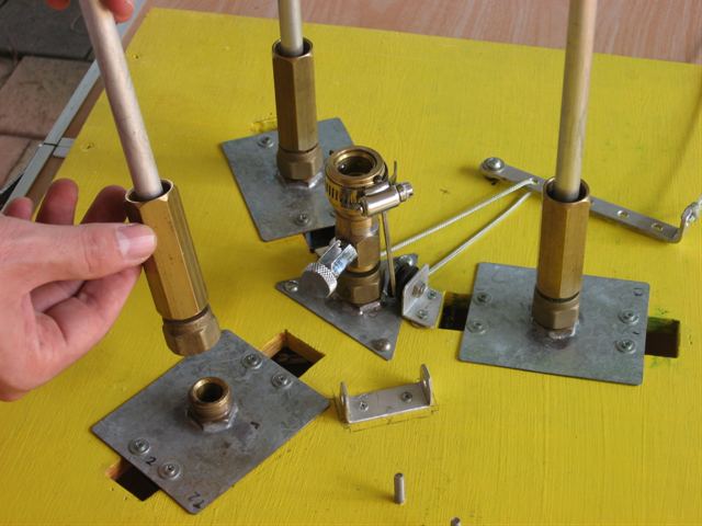
The 13mm Gluon booster nozzle.
Booster fill tubes. These are removable for
easier transportation.
Booster nozzle about to be inserted into the
nozzle seat.
Nozzle seats attached to the rest of the
launcher.
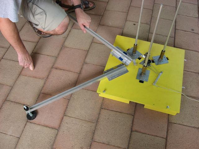
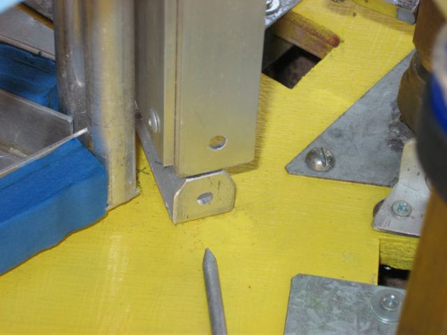
Guide rail legs are reused from our medium
launcher.
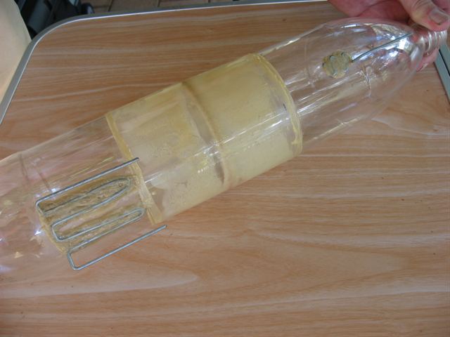
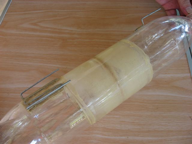
Detail showing the booster pins glued to the
bottle surface.
Side on view of the pins.
This view shows the location of the guide
rail lugs. One is at the bottom and the other
near the Cg.
Booster pins about to be inserted into the
corresponding main stage tubes.
Boosters are placed first on the launcher.
Guide rail about to be inserted over the top
lug.
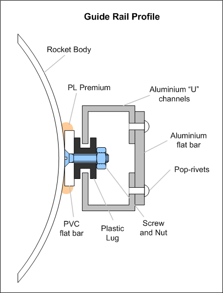
This diagram
shows the cross-section detail of the guide rail
and the guide rail lug.
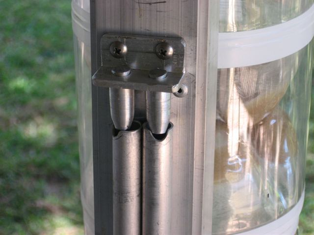
The guide rail simply slides into the top of
the guide rail struts.
The bottom of the guide rail is pinned
against the launcher to prevent it from coming
loose on launch.
Boosters are filled first and then capped.
The payload section is locked in place after
the main stage has been filled and tightly
capped.
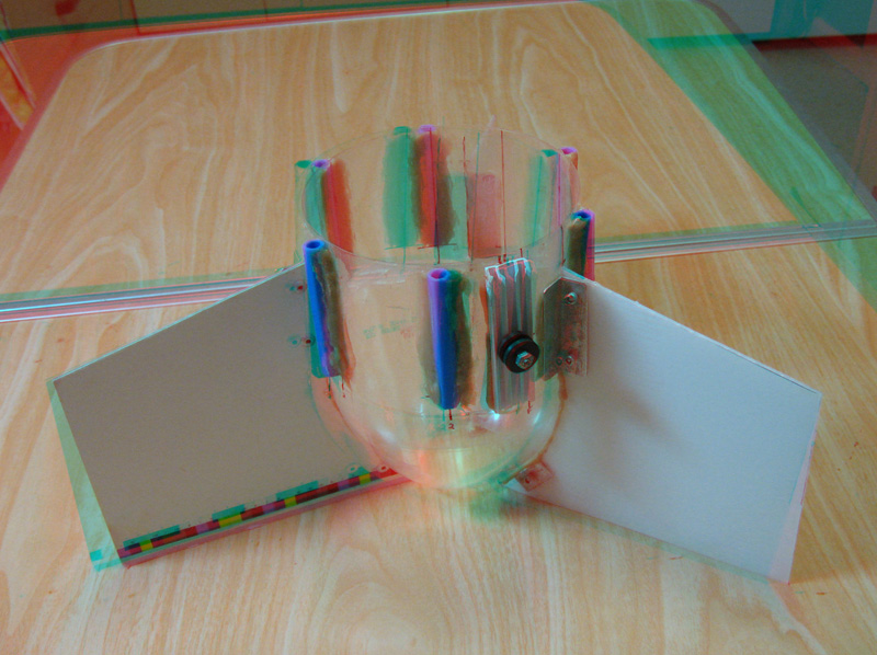
This is a detail of the removable fin
section with the Aluminium 7mm nozzle.
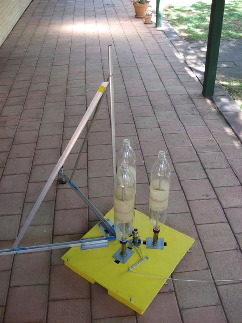
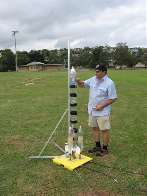
Getting ready to test the launcher as a
whole. Here is the Polaron IVd dummy for the
test.
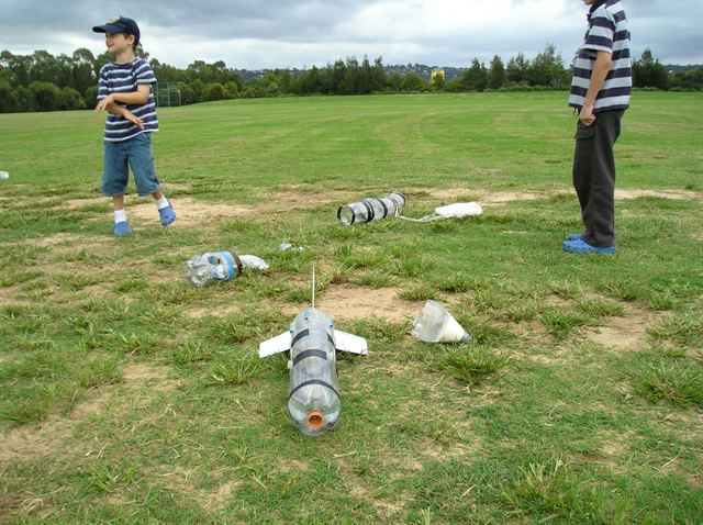
Making sure the stripes on kids are well
aligned with stripes on rockets.
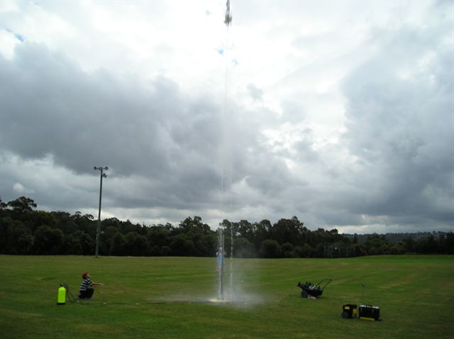
Success. Vertical take-off. All the boosters
stayed on, and fell of at the same time.
We know why we don't use the NOAA parachute
technique any more.
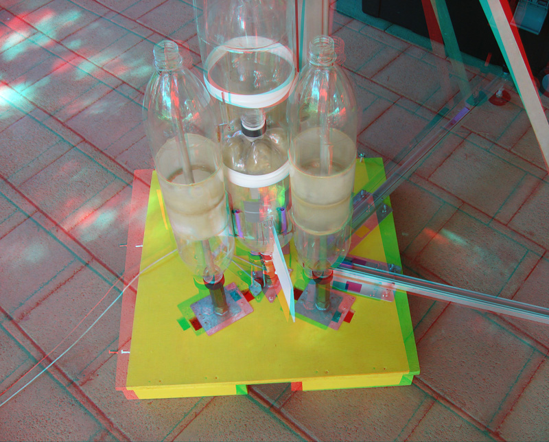
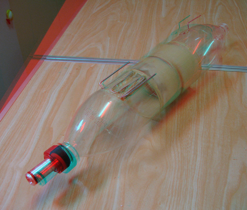
Okay, time to
put on your
3D glasses.
The assembled rocket.
The Gluon booster
Removable fin section
Under the launcher
Release head with nozzle seats
Payload section
Date:
11th March 2008
Location: Workshop
Conditions: Pleasant.
Team Members at Event: GK and PK.
In this weeks update
we describe the Polaron IV rocket and
launcher in detail. The Polaron IV rocket
was flown two weeks ago at the
last NSWRA launch event.
This rocket and launcher will be used in our
next round of developments as we increase
the capacity and strength of both the rocket
and boosters.
Polaron IV Launcher
Design methodology
We wanted to build a
flexible launcher for the next set of
planned rockets, and in particular ones with
boosters. As we look more seriously towards
reinforcing bottles we wanted to make sure
the launcher would be able to handle the
higher pressures. One design criterion
established early was that the launcher
should operate up to 500psi. When dealing
with design for higher pressures safety is
paramount. We always use the correct
fittings and properly rated materials. We
are lucky in that dad has had close to 45
years of commercial experience in designing
and building high pressure equipment for
SCUBA divers, fire fighters, the military as
well as experimental deep sea equipment. Any
high-pressure components that we create in
house always have a high safety margin.
We also realized that
depending on rocket materials and
configurations that for optimal results the
main stage would need to operate at
different pressures to the boosters. The
launcher needed to be capable of launching
both single nozzle rockets as well as
clustered rockets.
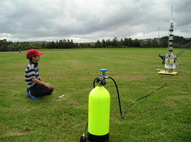
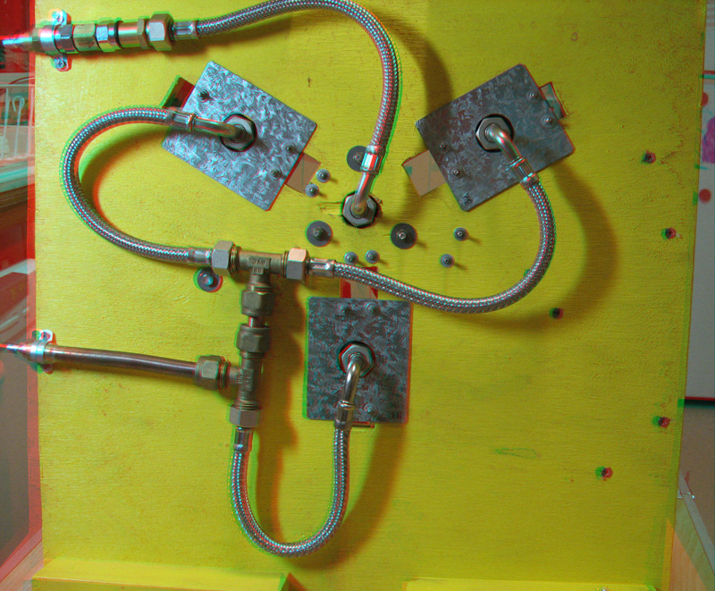
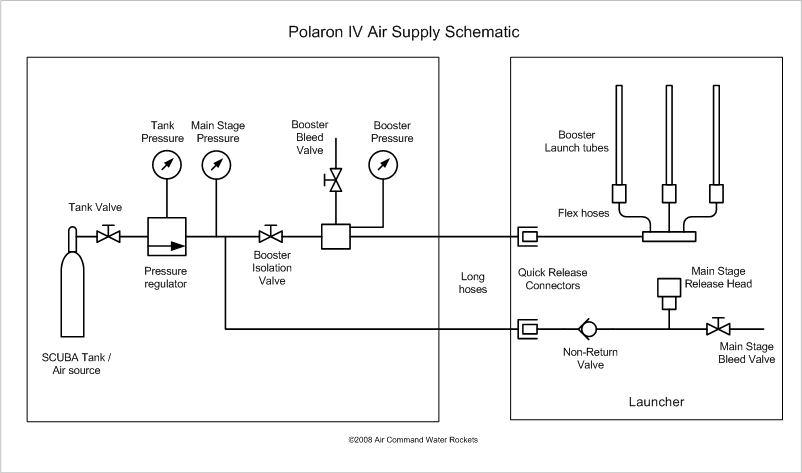
Air Supply &
Distribution
The air for the
launcher is typically supplied in compressed
form from a scuba tank via a commercial
pressure regulator, but can be connected to
an air compressor or a bicycle pump if
really desperate. There are two quick
release connectors on the side of the
launcher. One supplies the air to the
boosters and the other to the main stage.
We have now completed
a separate self-contained control panel with
all the pressure gauges, valves and bleed
valves. We will describe this in more detail
in future updates. The control panel
connects to the two quick release fittings
with two long hoses.
The main stage air
supply line has a non-return valve fitted
near the quick release fitting. This
prevents water from draining from the rocket
and entering the air supply hose.
Other than the flex
hoses all other fittings on the launcher are
brass, thick copper or steel. The flex hoses
are made of rubber encased in a stainless
steel mesh with stainless steel ends.
Diagram of the air
supply components (Click to Enlarge)
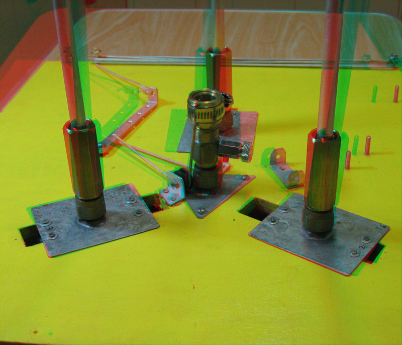
Sliding Booster
Nozzle Seats
The booster nozzle
seats are free to slide horizontally. The
reason for this is two-fold. It
allows us to vary the diameter of both the
main stage as well as the boosters depending
on a particular rocket design. The nozzle
seats just slide to the appropriate position
to keep everything aligned.
They also slide a
little by themselves as the rocket and
boosters expand during inflation. This
reduces the stress on the nozzles against
the seats.
The nozzle seats have
an integrated fill tube that doubles as a
launch tube for the boosters. The fill tube
fills the boosters with air only above the
water line. Each of the fill tubes is
connected together through the manifold
below the launcher. This allows the air
pressure to equalize between the booster
segments. By keeping the fill tube inlets
above the water line it prevents water from
transferring between the booster segments.
Doing the pressure
equalization on the launcher rather than the
rocket itself allows the rocket to be
lighter. It would also be quite difficult to
separate the three boosters if they were
connected to a single manifold on the
rocket.
The nozzle seats and
fill tubes are removable for easier packing
and transportation. The nozzle seat is just
machined from a section of brass and the
aluminium fill tube is epoxied in.
The fill tube rather
than being open at the top, is plugged and a
small hole is drilled from the side just
under the plug to let the air out. This was
done simply to stop water entering the
booster manifold while filling the boosters
with water from the top and also during
launch as the boosters clear the launch
tubes.
Release Head
The release head is
made from a brass 9mm Gardena mechanism. We
chose a good quality one that uses ball
bearings instead of the plastic tabs to
retain the main stage nozzle. The mechanism
is soldered to another brass section and is
screwed down in the center of
the launcher. The release head can be
unscrewed and replaced with a different
launch mechanism. The brass section directly
under the release head has a bleed valve
to allow the rocket to be
emptied should a launch abort needs to be
called. One problem with locating the bleed
valve here is that you need to approach the
pressurised rocket in order to release the
pressure. This is a safety issue and will be
resolved by allowing the bleed valve to be
turned remotely using a string. The bleed
valve cannot exist within the control panel
as it needs to be on the same side of the
non-return valve as the rocket. Putting the
non-return valve in the control panel would
allow too much water to drain into the hose.
A hose clamp holds two
ends of a string to the sliding part of the
release head. This string is fed through two
pulleys at the base of the release head that
turn the vertical motion into a horizontal
one. The string is loosely threaded through
a hole in a lever to allow the tension on
both sides of the release head to be
balanced.
Because the spring in
the release head is quite strong, we use the
lever to reduce the amount of force
necessary to release the rocket without
causing the launcher to tip over in the
direction of the string being pulled.
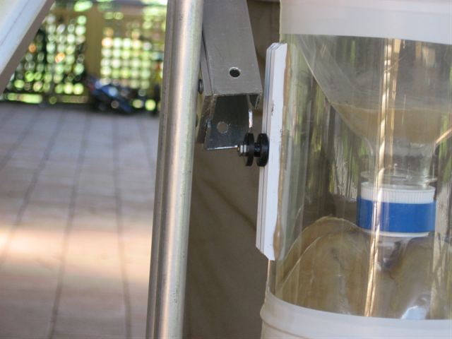
Guide Rail
The guide rail
consists of two U channels of aluminium
attached so that they face each other with a
7mm gap between them. We made the guide rail
2m long because we expect the rocket length
to increase in future experiments. It also
gives the rocket plenty of time to get up to
speed. The guide rail is removable for easy
transportation. We went with the single
guide rail as opposed to the three we have
been using for simplicity. There isn't a
whole lot of room on the launcher especially
with the three boosters in the way. We went
with this design as it is much stiffer than
a launch rod that could easily bend under
the loads of a higher-pressure launch. The
disadvantage is that the rocket has to have
guide rail lugs that add weight and drag.
You can ask questions or
leave comments about the video
HERE
(If the video does not play, try the latest
Flash player from Macromedia)
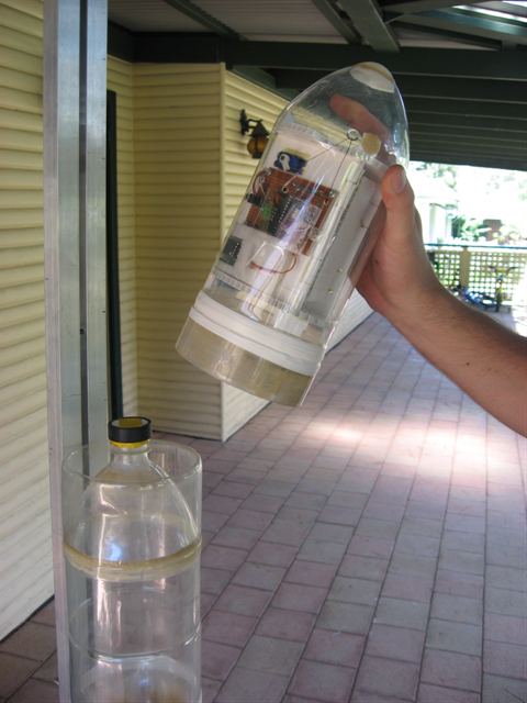
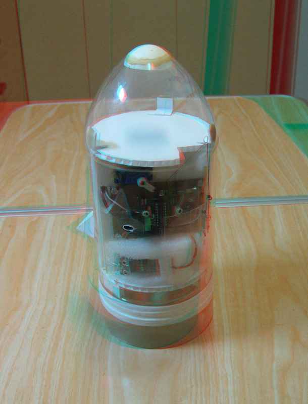
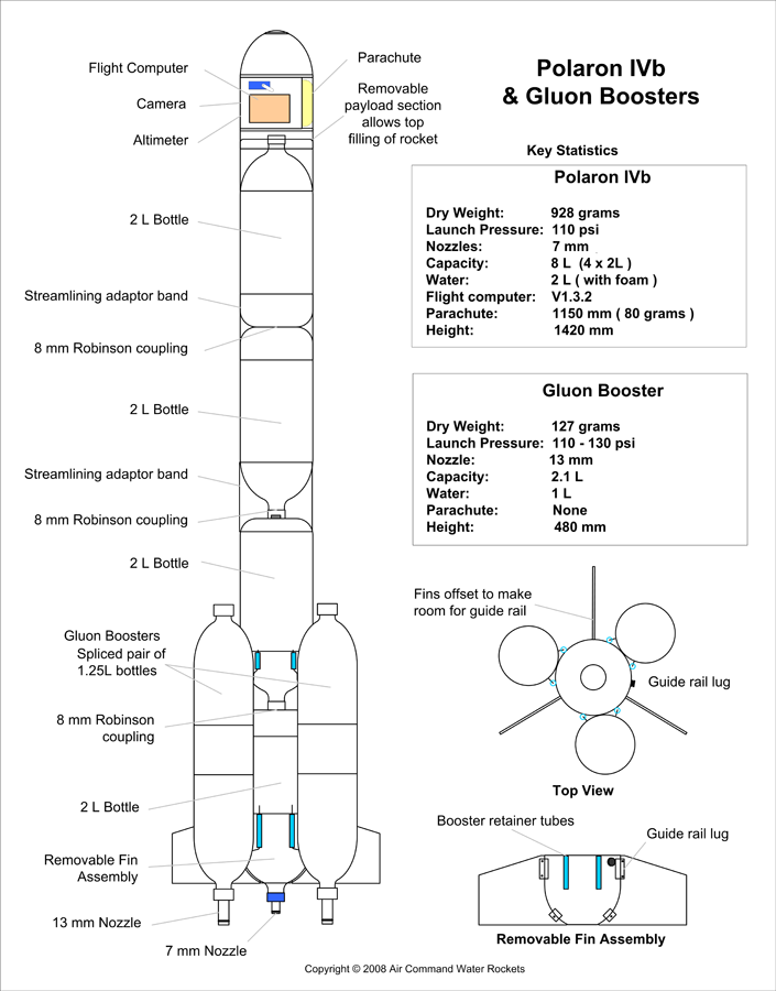
Polaron IV rocket
Payload Section
The
payload section is composed of the inner
support structure that holds all the
components, and an outer aerodynamics shell
with a parachute door and latch. The inner
structure is made from corrugated plastic
used for sign making. (Also known as
Coroplast, Correx, Corriflute or Twinplast).
We just use contact glue to join these
together.
The
inner support structure has the following
components attached to it:
V1.3.2 of our flight
computer;
A 6V battery pack
made out of two CR123A lithium
batteries;
FlycamOne V2 video
camera with 2Gb SD card;
MOD4 Zlog altimeter;
8g micro RC servo;
and
And the spring loaded
parachute deployment bay.
The
outer aerodynamics shell is made from a 2 L
bottle with the base and neck cut off. To
get the nice elliptical nose shape, we glue
in half a ping pong ball into the hole left
by the removed bottle neck.
The
inner structure simply slides into the outer
shell and is retained by stops glued to the
inside of the outer shell.
Body
The pressure chamber
part of the rocket is made from 4 x 2 L
bottles Robinson coupled together. The top
bottle is turned neck up so that we can fill
the rocket while it is on the launcher. This
makes it a lot easier to align all the pins
and tubes on the boosters without spilling
the water from the bottom of the rocket.
The bases of the
bottles are reinforced with a second layer
jacket made from a 2.25L bottle and heat
shrunk with PL premium glue sandwiched in
between.
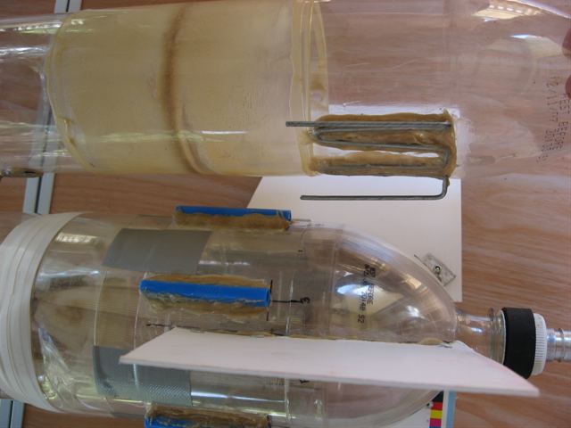
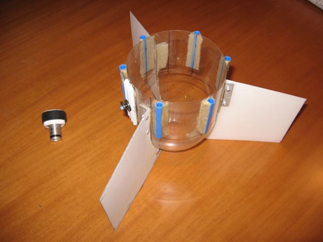
Removable Fin Section
The fin section of the
rocket is removable. This section has all
the fins with the booster retention
tubes attached as well as the lower guide
rail lug. The tapered part of this section
ensures an even spread of force on the
bottom of the pressure chamber. It also
helps reinforce the lowest bottle. All the
components are attached with PL premium.
Guide Rail Lugs
The guide rail lugs
keep the rocket attached to the guide rail
and help it steer in the correct direction
as it accelerates and before the fins have a
chance to start working. One lug is attached
at the bottom of the rocket and the other is
near the center of gravity of the rocket.
The lugs are glued to short lengths of
extruded PVC bar. This gives the attachment
point some rigidity against the soft PET
bottle.
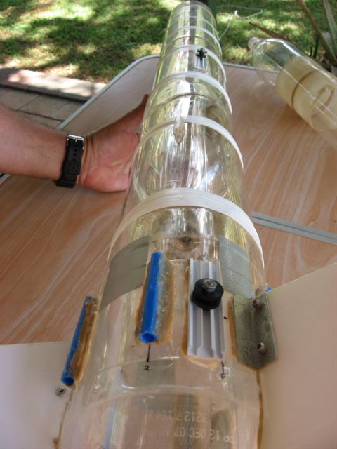
Booster Retention
Mechanism
The boosters are
attached to the main stage with a simple pin
type arrangement. The main stage has a pair
of tubes (made out of ballpoint pens) glued
to the surface. These tubes support the full
weight of the main stage during the thrust
phase of the boosters. The boosters have
opposing pins (made out of coat-hanger wire)
glued to their surface. A third pin is
located near the top of each booster that is
not load bearing but keeps the booster
aligned with respect to the main-stage axis.
This pin is offset to the side to allow the
booster to sit flush up against the main
stage.
While on the launch
pad the boosters are free to move out of
their nozzle seats. When the main stage is
locked down in the release head, the
tube/pin arrangements keep the boosters from
flying off. When the main stage is released,
the boosters produce more thrust than the
main stage and that keeps them pushed up
against the tubes and attached to the main
stage. As soon as the boosters stop
producing thrust, air pressure on their
nosecones pushes them back and the pins
slide out of the tubes.
We favoured this
arrangement rather than holding down all
nozzles individually because it makes it
much easier to synchronize the release of
all of them. If they weren�t exactly
synchronized, and one of the boosters let go
even a fraction of a second later than the
rest, its pins might slide out of the tubes
in that instant, and you might end up with
an out of control rocket.
Polaron IV Rocket. Click to enlarge
Dummy Main-Stage
Flight Tests
Two days before
launching the real rocket we built a dummy
main stage of equal weight and size to test
to see if the whole system would work as
expected. We did not want to use the actual
rocket as the payload is quite expensive.
The dummy main stage consisted of four 2
liter bottles joined together, but only the
lowest 2 L bottle was pressurised. We wanted
to include the approximate weight of water
that would exist in the real rocket. We
filled it up with 1.5L of water so there was
only about 0.5L of air in the rocket. This
was just enough to get the water out of the
rocket in flight so that it would not be
heavy on the way down.
We fitted the top of
the main-stage with a retired
NOAA nosecone and a parachute to help
guide it gently back down. We also filled a
zip-loc bag in the nosecone with about 150mL
of water to provide extra ballast as the
real rocket payload is a little heavier than
the NOAA nosecone.
We launched the rocket
at only 100psi as that was enough to prove
the concept. The first flight was excellent
and all systems worked as expected. The
nosecone also came off at apogee and the
rocket landed well.
The second flight was
equally nice and straight, with the boosters
separating at about the same time. On both
flights we didn't notice any deviation from
the straight path caused by uneven thrust.
This was very encouraging. Although on the
second flight the parachute of the main
stage failed to open and the rocket
disintegrated on the ground. The removable
tail section and the guide rail lug further
up the rocket survived without any damage
and were fitted to the real main stage that
evening.
Here is a video of
those dummy main-stage test flights.
You can ask questions or
leave comments about the video
HERE
(If the video does not play, try the latest
Flash player from Macromedia)
Setup and Launch
Operations
The following list
describes all the steps from launcher setup
and rocket assembly at the launch site to
launching the rocket.
Assemble launcher
including fill tubes, and guide rail
legs.
Connect air supply
lines to control panel.
Apply silicone grease
to the fill tubes and nozzle seats and
the release head.
Apply silicone grease
to the booster nozzles.
Seat all the boosters
in the nozzle seats.
Apply silicone grease
to the main stage nozzle.
Slide the main stage
over the booster pins, and lock the main
stage nozzle into the release head.
(Verify all the booster pins are located
inside the retaining tubes.)
Slide the guide rail
in over the guide rail lugs and lock it
in place.
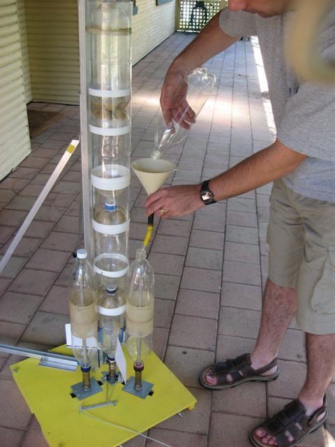
Fill the boosters
with water using a funnel.
Cap the boosters
tightly.
Fill the main stage
with water using a funnel. We use a long
funnel that allows us to get past the
first coupling so that water does not
remain in the top bottle base.
Cap the main stage
tightly.
Lock the
nosecone/payload section in place.
Pack the parachute in
the nosecone.
Configure and arm the
flight computer.
Start the altimeter
recording.
Start the video
camera recording.
Clear the launch area
of all personnel.
Pressurise the
boosters to the required pressure,
checking gauges on the panel for leaks.
Pressurise the main
stage to the required pressure, checking
gauges on the panel for leaks.
Verify that launch
criteria are not violated. These include
wind speed, people wondering close to
rocket, or nearby aircraft.
Fast takeoff,
Straight flight path, with boosters
separating simultaneously. Parachute
failed to open. Dummy main-stage
destroyed with removable tail
section sustaining no damage.