Introduction
This is the build log of our rocket
project called "Inverter". The log is in chronological order so to
see the most recent post you need to
Jump To The Bottom.
You may need to refresh this page to see any
latest updates.
Design
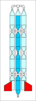 |
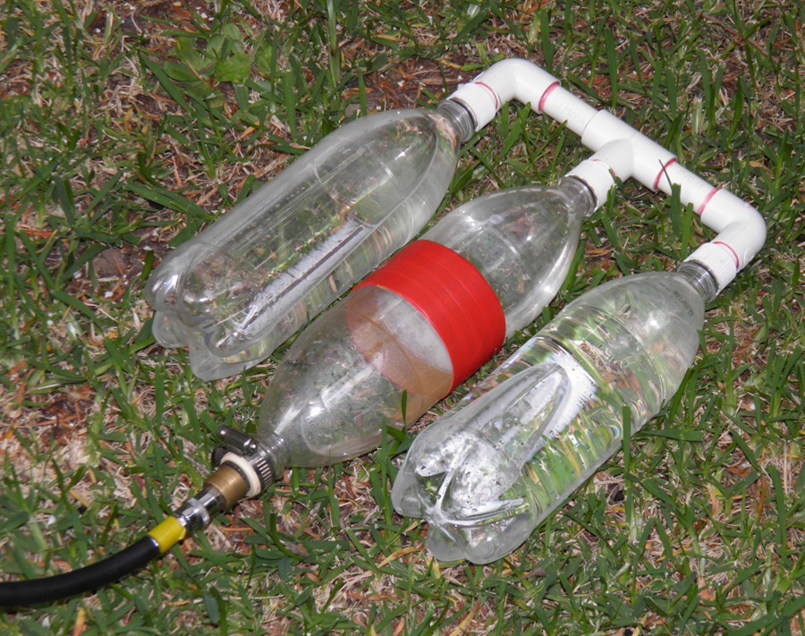
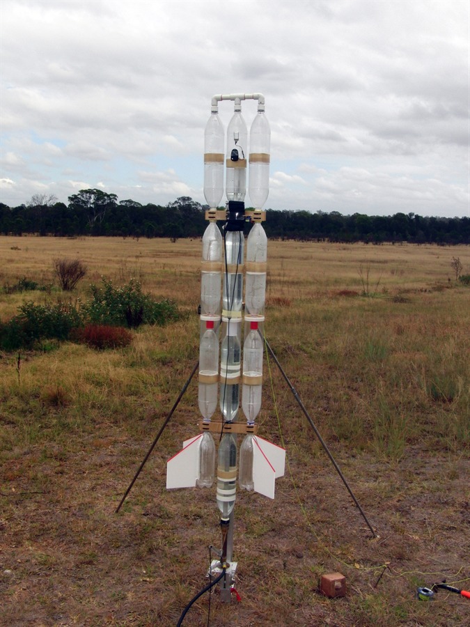
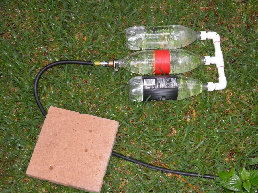
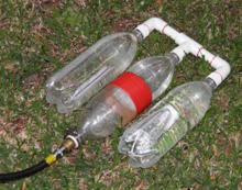
The Inverter rocket is based on a central
pressure chamber that mostly contains water
and two side mounted air-only pressure
chambers. They are joined together at the
top using an air manifold made from PVC
tubing. The rocket's name comes from the fact that
the flow of air is inverted inside the
rocket.
This approach allows one to build a large
capacity single nozzle rocket out of regular
bottles without the rocket being too long.
This concept has been used over the years by
water rocketeers. Here are some
examples:
Because the rocket only uses a single
nozzle it simplifies the launcher design and
allows us to use our existing one without
modification. The flat rocket is also easy
to attach to the guide rail.
We chose to use 2 air chambers in order
to reduce the overall drag and since water
rockets are also usually filled to 1/3 water
it meant we could fill the central segment
almost completely with water. Having a
longer central segment also meant that water
could be distributed vertically in the
rocket and hence helping to increase the
stability.
|
Build Log
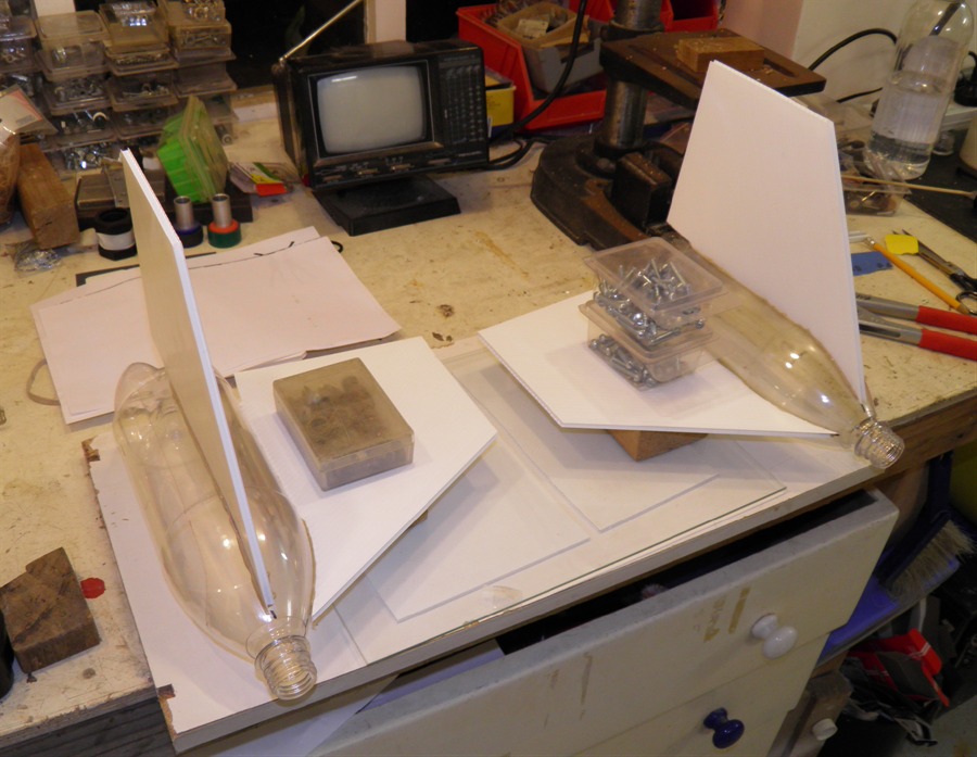
12th December 2012
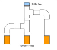
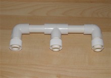
- Designing the manifold. Since this was
going to be an important part of the rocket
we decided to start with the manifold. We wanted to have an opening on the top
of the central segment so that we could fill
it with water once it was on the pad. It
would be difficult to turn it upside
down to fill it and not have the water flow
into the air-only segments. The other
alternative would have be to fill the
rocket through the nozzle, but our launcher
isn't set up for that, so we chose to simply
add an opening at the top of the rocket.
We wanted to use the tornado couplings so
that we could easily assemble or replace the
segments as needed, and use our standard
components. We added enough spacing between
the manifold pipes to allow us to use wider
segments in the future.
The manifold looks funny the way it is
because we wanted to have a 4 way connection
above the central segment, but they don't
sell them at the local hardware shop. They
only sell T-connectors. When I asked the
sales guy, he said "This is the plumbing
section, this isn't the furniture section."
A little bewildered I said "OK" So either
there is something about plumbing that only
needs T-connectors, or somewhere out there
there is furniture made from PVC piping.
Checking on-line, I can see there are X
pieces available for PVC pipes... hmmmm.
Based on the layout below we bought the
necessary components at the local hardware
store.
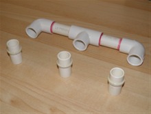
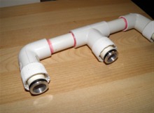
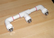
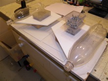
13th
December 2012 - We cut out
all of the pieces and assembled them with
the tornado couplings, and weighed
everything... 235 grams was way too much for
just the manifold! It was time to re-think
the overall design to reduce the weight so
we decided to change the design to just a T
and 2 elbows. We also decided against using
the tornado tubes and would attach the
captive caps to the PVC tubes. Sealing would
be achieved by soft rubber washers under the
caps. We were going to loose the ability to
fill the rocket from the top, but would
still be able to if the whole manifold was
removed.
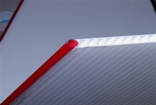
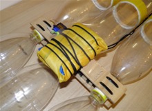
Original manifold plan turned
out to be too heavy,
but did have access to the
center bottle. |
|
|
|
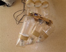
15th
December 2012 - Machined up 3 PVC rings
that would hold the captive caps. We glued
these with epoxy to the PVC tubes. We also
obtained the bottle caps from the local
supermarket. We got these from hand wash
detergent pump packs. Now we have at least a
6 month supply of hand washing detergent.
The pumps in the caps were cut out and the
hole in the cap enlarged on the lathe so it
would fit on the PVC tube.

Parts cut out for the lighter
manifold |
Test fitting the whole thing
together |
|
|
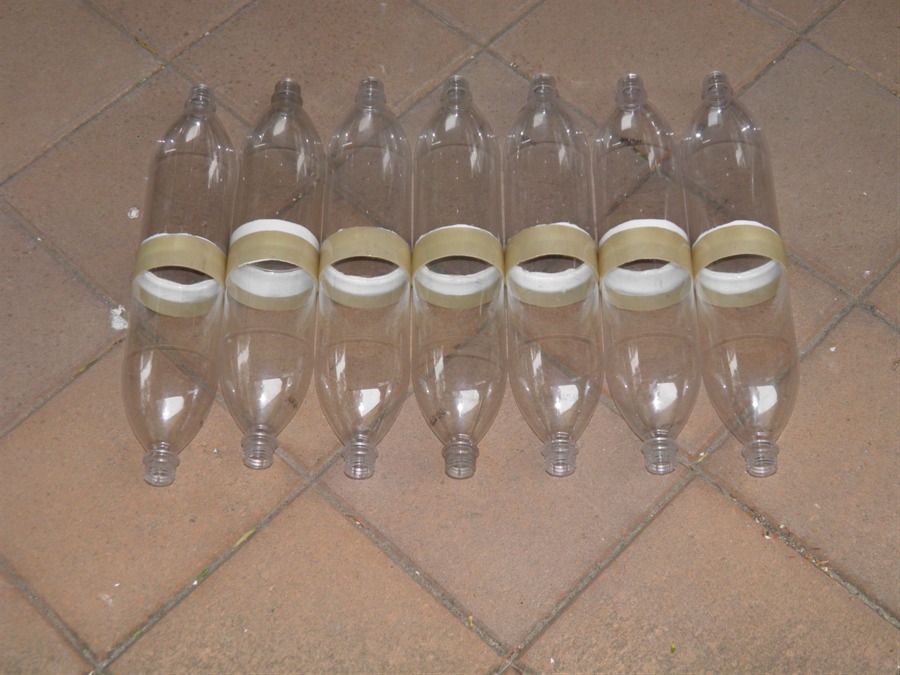
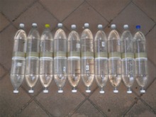
18th
December 2012 - Finished making 7 new
90mm spliced pairs with the narrow sleeve.
We had used up most of our spare spliced
pairs last year for the commercial and so we
had to make a few for this rocket. We want
to use 3 - 4 spliced pairs per segment on
this rocket.
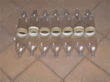
7 new spliced-pairs |
|
|
|
28th
December 2012 - We glued the whole of
manifold together today using PVC cement.
Partially glued together |
|
|
|
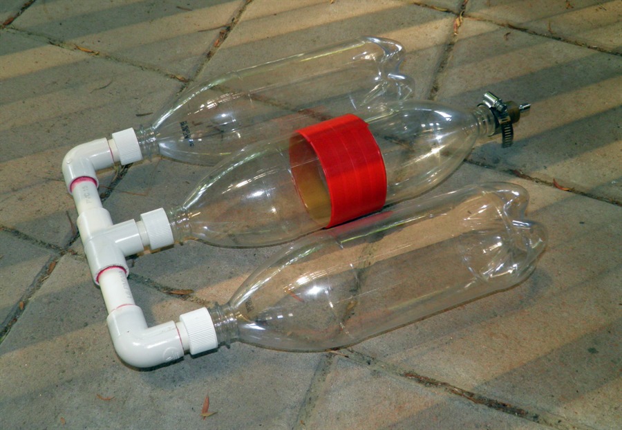
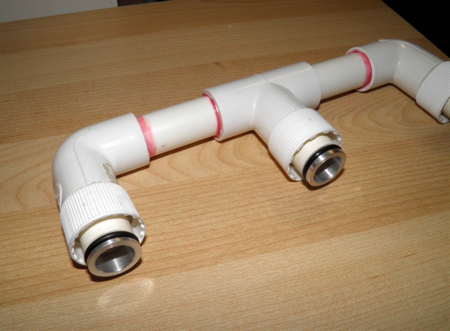
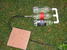
1st January
2013 - Pressure testing the manifold. We
tried pressure testing the manifold today
but have had several problems with getting
good seals. We would fix one leak, but when
pressurised to a higher pressure another
would leak. We decided that this was going
to be too unreliable especially if we were
going to pull the manifold off to fill the
rocket on the pad. So it was decided to
switch to plan B and go with the o-rings.

Ready for first pressure test -
had some leaks |
Test fit of what the Inverter
rocket will look like |
|
|
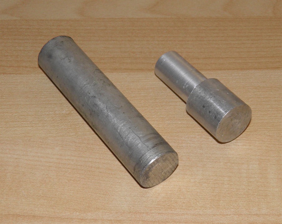
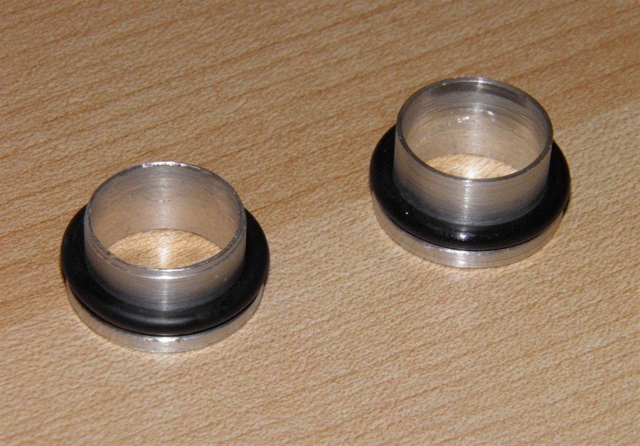
7th January
2013 - Machined up 2 of the three o-ring
sleeves that will fit into the end of the
manifold. Each sleeve is made of aluminium
and weighs 2 grams. These will be glued into
the ends of the tubes with epoxy. The hole
in the sleeve is 16mm for maximum airflow.
The wall thickness is around 0.75mm.
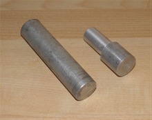
Stock aluminium |
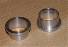
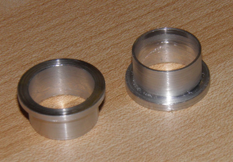
Sleeves machined to fit |

..with o-rings |
Test fitting rings into the
manifold |
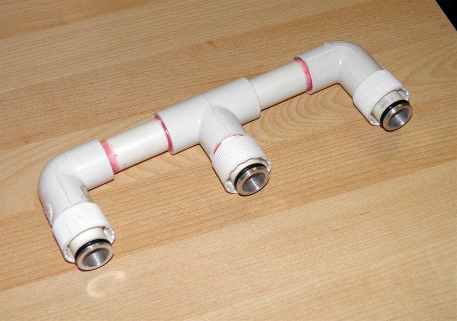
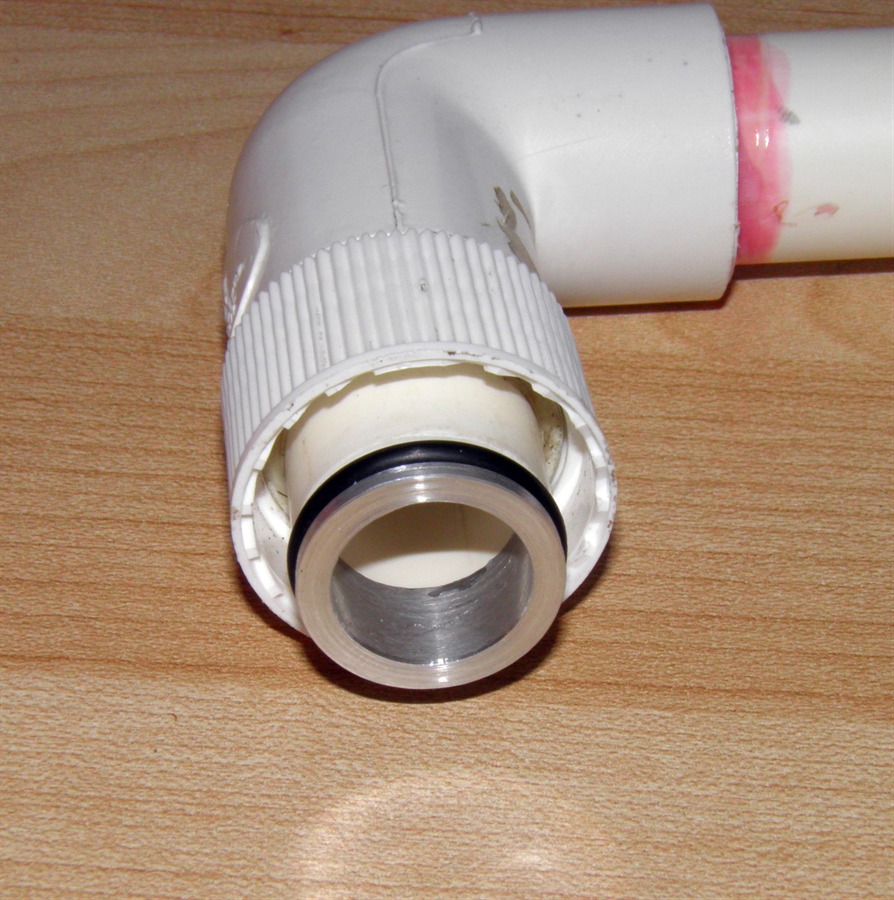
8th January
2013 - Machined up the third o-ring
sleeve. We glued all the the o-ring sleeves into
the manifold with
epoxy.
All 3 sleeves glued in |

Close up of the sleeve in place. |
|
|
12th January
2013 - We pressure tested the air
manifold to 120psi today. There were no
leaks and the manifold was easy to put on
and take off again.
Pressurised to 120psi - no leaks |
|
|
|
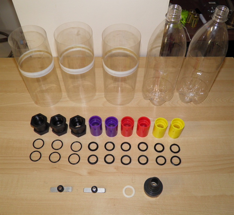
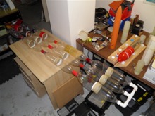
15th January
2013 - Gathered up all the tornado
tubes, nozzle, guide rail lugs necessary for
the rocket. We are using 22mm tornado tubes
on the central segment since it is going to
be passing water through them. These should
be hopefully big enough not to choke the
flow too much since the nozzle is only 16mm.
The cross sectional area of the tornado
tubes is roughly double that of the nozzle.
We decided to make up three more spliced
pairs of bottles for this rocket so we
prepared the bottles for those as well.
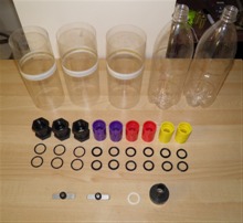
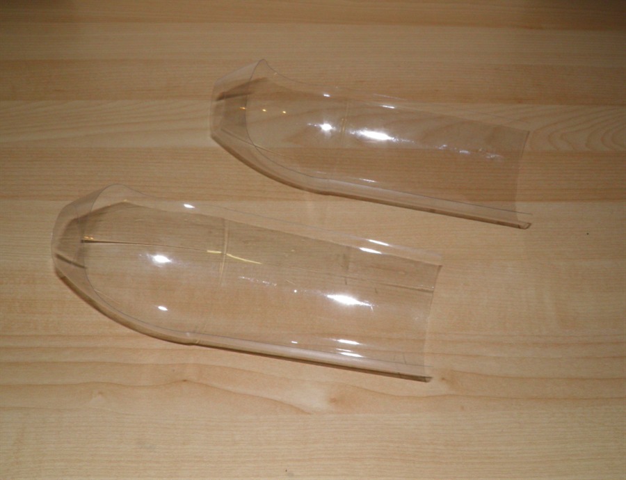
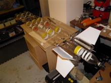
Fairings, tornado tubes with
seals, nozzle and guide rail
buttons. |
|
|
|
16th January
2013 - Spliced the the 3 new
spliced-pairs
with Sikaflex today. Only 10 more days to
launch so we need to hurry up so the glue
has enough time to fully cure. Prepared the
sleeves for these as well.
17th January
2013 - Finished gluing the sleeves on
with PL premium today. We also did some
preliminary simulations to get an idea
of how the rocket is expected to perform. It
looks like it should do around 500 feet at
120psi. It is hard to enter this particular
rocket's parameters accurately into the
simulator, but at least we have a general
idea. It's a little higher than what we are
actually
expecting, especially with a high drag
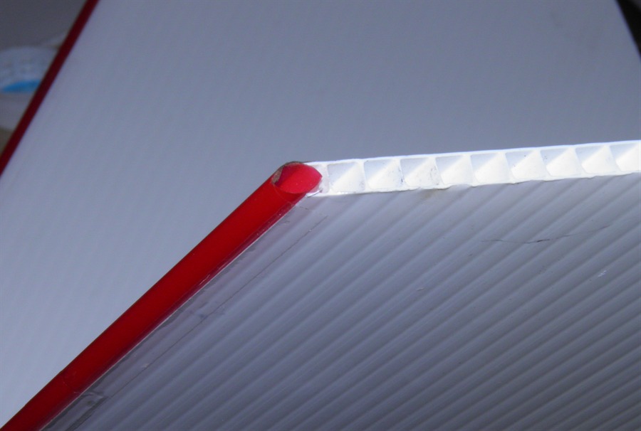
rocket like this.
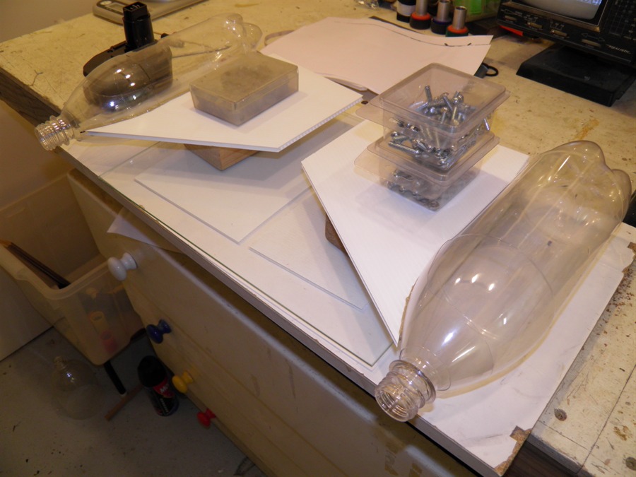
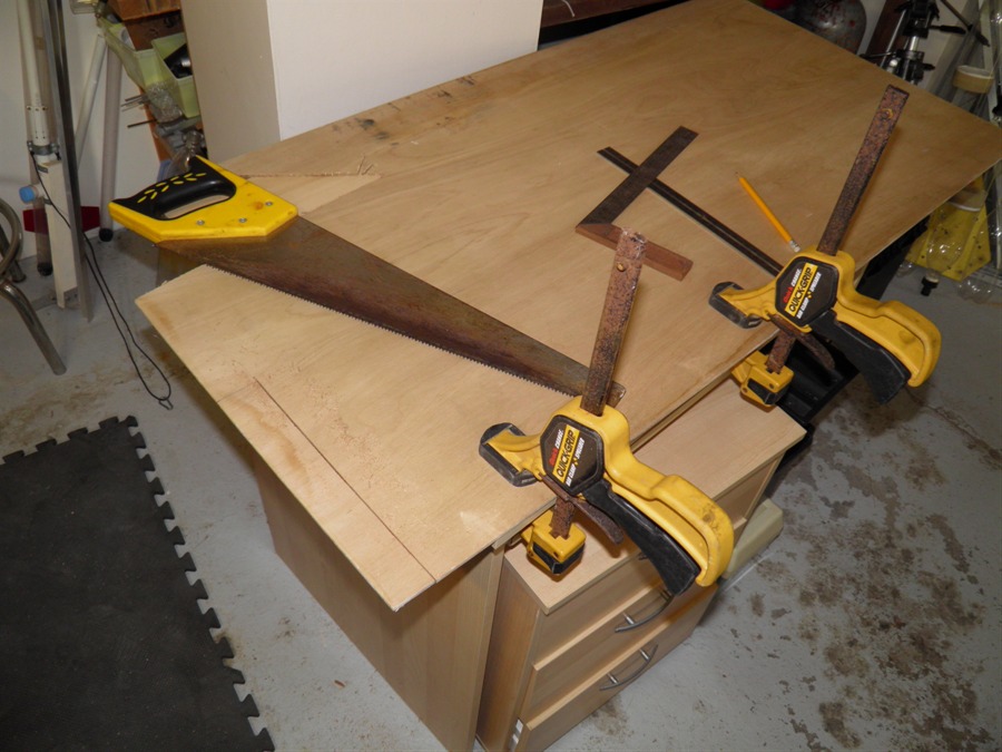
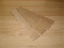
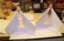
19th January
2013 - Cutting out corriflute fins.
We first made a cardboard template to trace
them out evenly on the sheet. There is a
huge Bunnings store that has just opened up
about 10 minutes away from our place.
They now sell the 5mm and 3mm corriflute
sheets, so very easy to get. We also cut out
the fin cans that the fins will be glued to.
The fins are attached to the lowest single
bottles on the air segments. The 2 fins on
each side are at 90 degrees to each other.
Because the rocket needs to be screwed
together, we allow the fin can to rotate so
that once everything has been tightened we
can rotate the fins to the correct position.
These will be then simply taped in place
like we do with all of our fins.
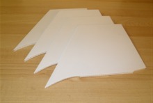
Fins cut out from 5mm corriflute |
Fin cans |
Gluing fins to the fin cans |
|
We cut out the 4 plywood brackets that
will hold the segments together. We test
drilled a couple and tried sandwiching a
tornado tube between them and then secured
it with a cable tie. I think this system
should work. If not then we'll have to think
of something else. One concern that we have
is that the rocket may twist on itself. Well
that's part of the fun of trying to fly this
rocket.
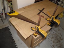
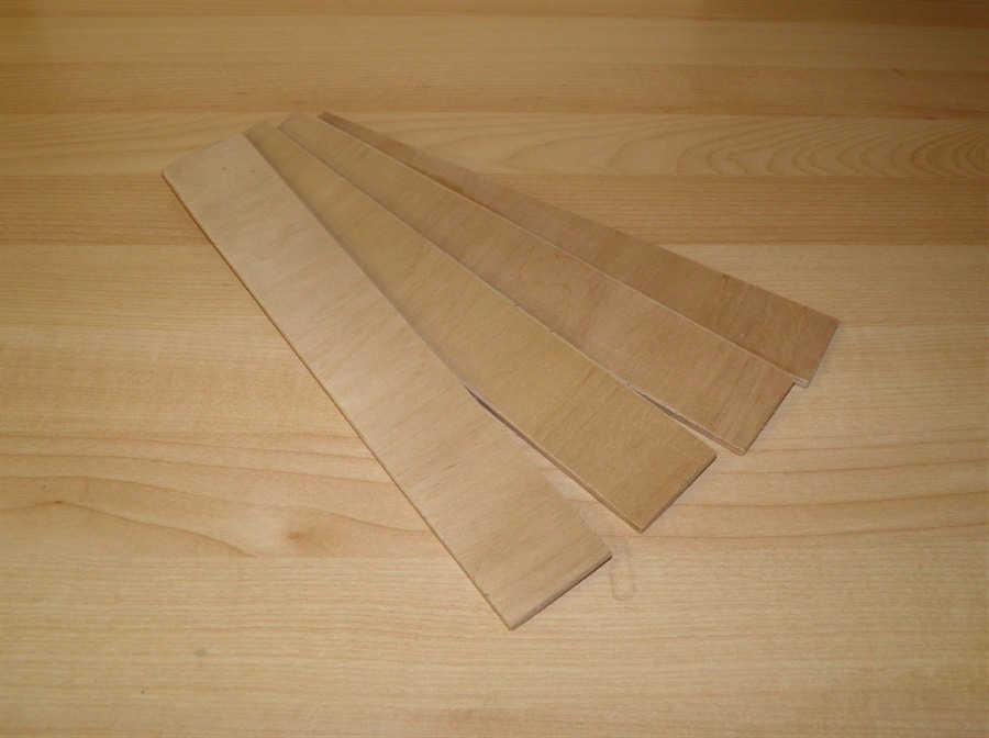
Cutting out struts from a sheet
of plywood |
4 plywood struts. 40mm x 260mm. |
|
|
20th January
2013 - Gluing the second set of fins to
the fin can. When these cure we will add Sikaflex fillets to the fins.
We also arranged the bottles to go on the
rocket as the black tornado couplings are
about 4mm shorter than the commercial ones.
We need to make sure the tornado tubes
remain in line so we can attach the
brackets. Luckily the spliced pairs of
bottles turned out in various lengths (+/-
5mm) , so we picked the longer ones for the
central segment and the shorter ones for the
outer segments. We need to get cracking
before Saturday because we still need to
pressure test all the bottles, and add the
parachute deploy mechanism.
Gluing the second set of fins |
|
|
|
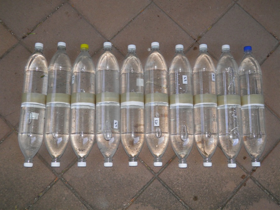
21st January
2013 - The boys helped pressure test the
10 spliced pairs today to 125psi. To much of
John's disappointment none of the bottles
exploded. :) With the pressure tests done,
we can now assemble most of the rocket. We
added the Sikaflex fillets to the fins as
well.
10 spliced-pairs ready for
testing |

Paul helping test the splices |
Sikaflex fillets on the fins |
|
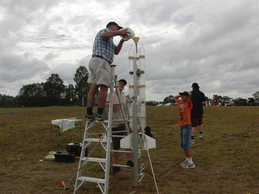
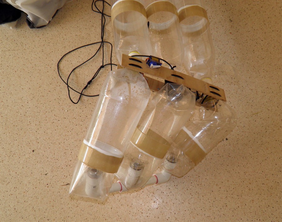
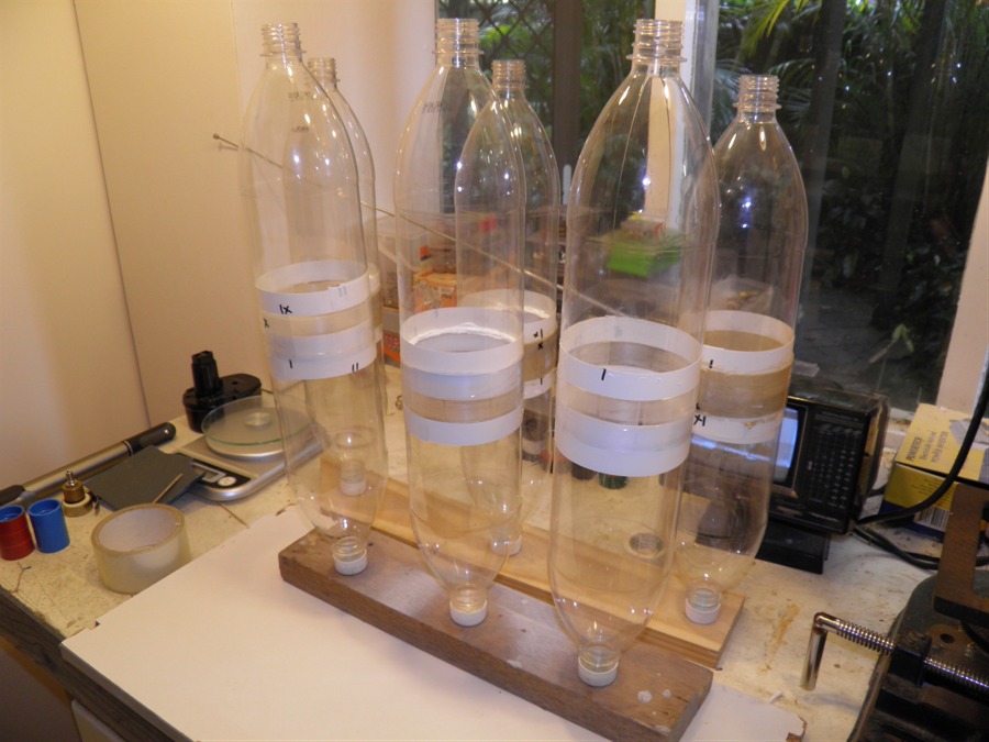
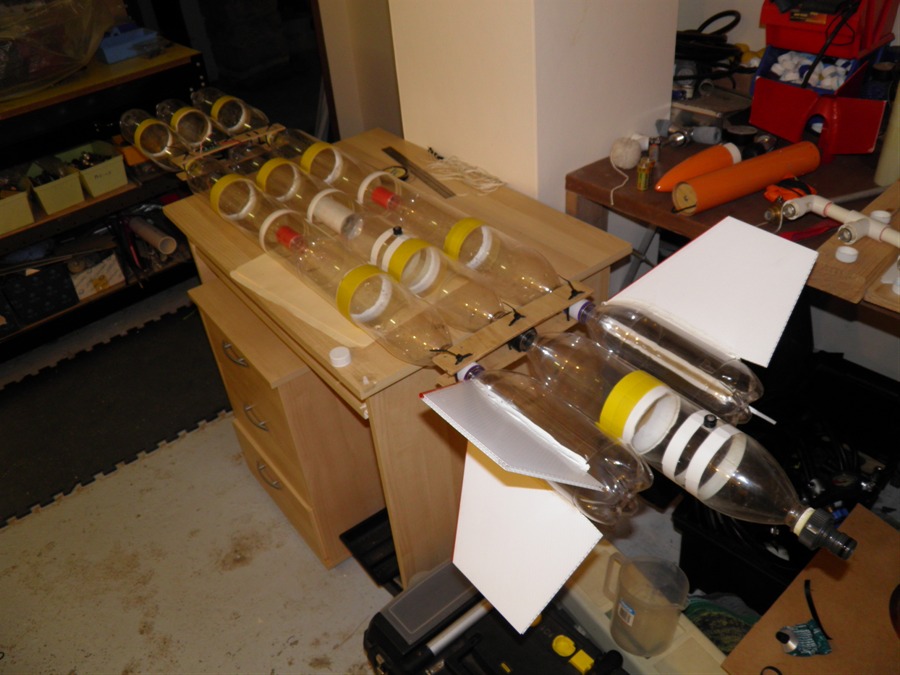
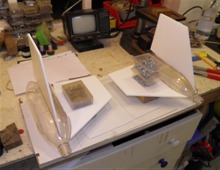
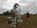
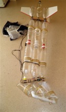
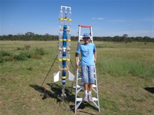
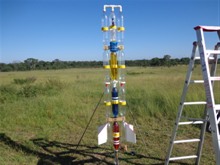
22nd January
2013 - We test assembled the rocket
today so that we could see what it will be
like when set up on the pad ready for
filling with water. We will definitely need
the ladder for this one as well. The rocket
is still missing its parachute deployment
system which is scheduled for tomorrow. We
weighed the rocket as it stands without the
recovery system and it has come in at close
to 1500grams.
While assembling the rocket I noticed
that the bottles were scratched in one
place. This must have been caused by
inserting the bottles into the test
cylinder. We will line it next time to avoid
any further scratches. Hopefully the
scratches aren't enough to weaken the
bottles.
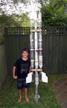
Assembled rocket |
|
|
|
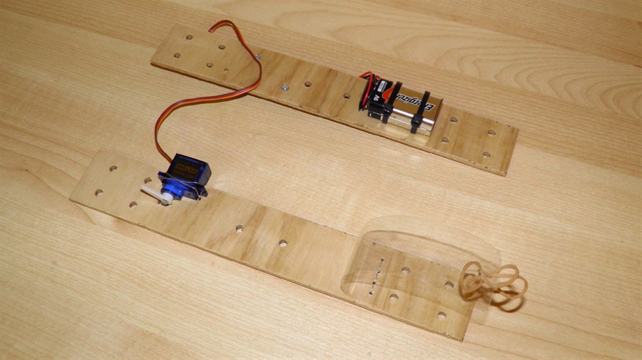
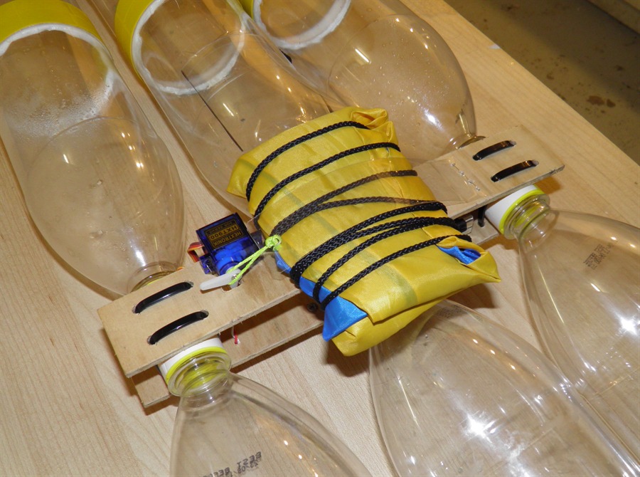
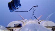
23rd January
2013 - Today we built the deployment
mechanism for the rocket. Because of its
size the rocket is using the larger 800mm
diameter parachute. The deployment mechanism
is very simple and consists of the parachute
being pinned down by a strip of PET plastic
held against one of the plywood struts. A
servo motor is connected to the STII to release
the door. There is no spring to eject the
parachute, it simply just let's it go into
the air stream. The parachute will be
attached to two separate points on the
rocket so it comes down sideways. It will be
interesting to see how much it will swing
side to side on the way down. We have
attached the struts to the tornado tubes
with cable ties.

Struts with deployment mechanism |
The reverse side has the battery |
|
|
24th January
2013 - Finished preparing the rocket,
We added drinking straws to the leading edges of
fins to make them more aerodynamic. KFC
straws are great for this as they fit nicely
in the 5mm Corriflute.
Fin leading edges |
|
|
|
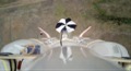
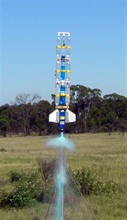
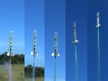
26th January
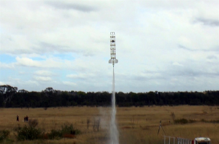
2013 - Launch day. The full launch
report is available here:
Day 129
Filling with water |
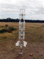
Ready to go |
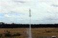
Maiden flight |
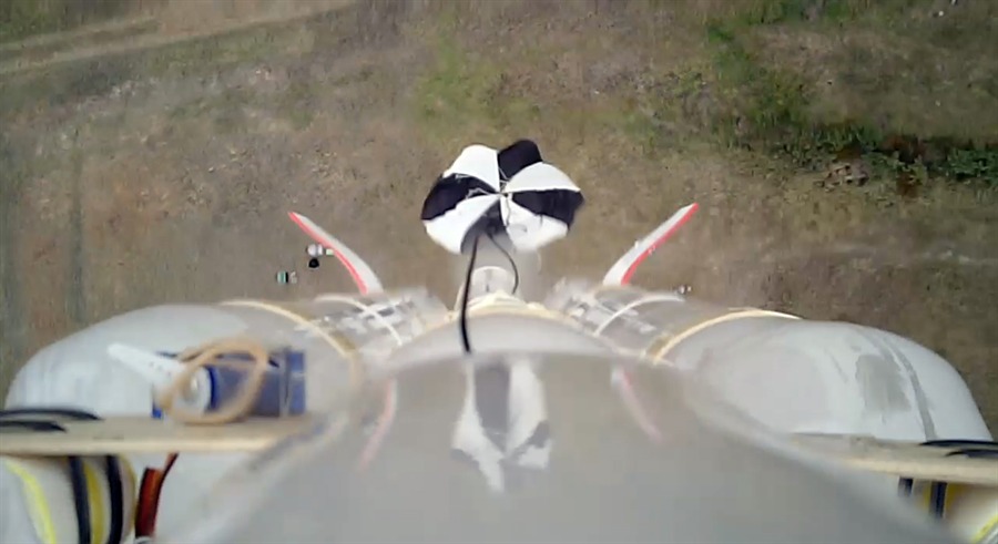
Onboard video frame |
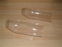
27th January
2013 - We took the rocket completely
apart and discarded the damaged bottles. We
inspected everything for damage and really
the only things that need to be replaced are
the bottles and the parachute. We started
preparing the 6 new bottles for splicing.
Damaged bottles |
Only the bottles are damaged |
|
|
28th January
2013 - We spliced the six bottles with
Sikaflex today and prepared the sleeves that
will go over them. We also re-glued the
retaining ring on the manifold tube with the
24 hour epoxy. This retaining ring holds the
captive cap on the tube and stops the bottle
from flying off. The parachute also got an
inspection, and we will replace it with a
different one for the next flight.
2nd February
2013 - Today we pressure tested the
manifold again to 130psi to make sure it
wasn't damaged during the landing. Luckily
the top bottles acted as a shock absorber so
it's fine. The bottle splices were also
finished today with the sleeve being
attached with PL. We'll wait 4-5 days for
the splices to fully cure before testing
them. I also looked over the deployment
mechanism and realized that the one main
difference between this one and our previous
successful incarnations of it were that they
used the hinge pin method to hold the
parachute in place. This is a much more
secure connection of the door and does not
have the same loading problems. While the
rubber band stretches under load, the hinge
pin doesn't. The hinge pin method will not
work easily in this setup but we'll
implement something more secure.
Re-testing the manifold to
130psi |

Making more splices |
|
|
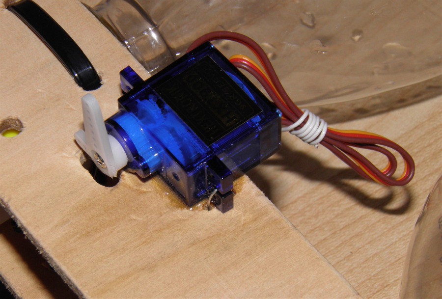
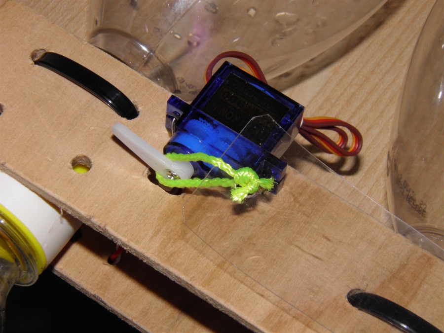
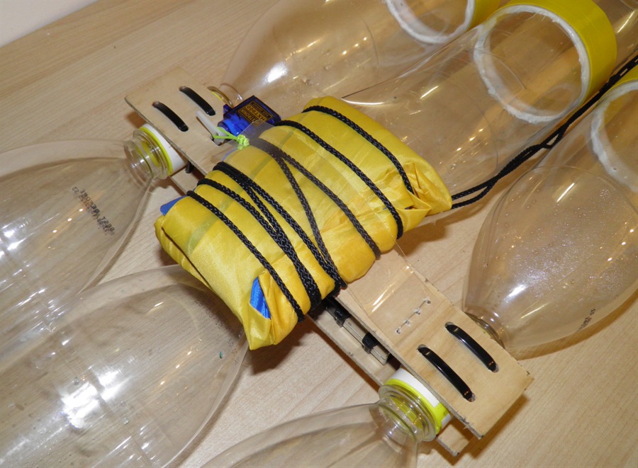
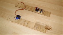
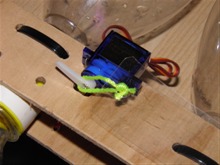
4th February
2013 - We made some improvements to the
deployment mechanism today. The servo was epoxied to the plywood strut so that it is a
lot more solid. Before it was just wired to
the strut. We also replaced the rubber band
with a loop made of nylon rope. This now
prevents the parachute door from stretching
open under load. Once we assemble the rocket
we will also add a little platform under the
parachute so it can't slide out from under
the door.

Epoxied Servo |
Nylon loop replaces the rubber
band |
|
|
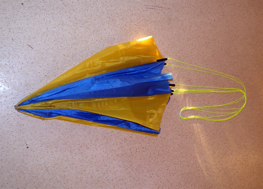
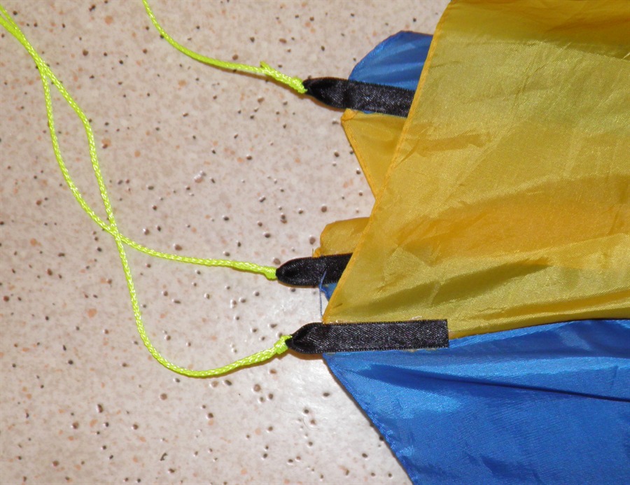
5th February
2013 - We made a new parachute today out
of an old umbrella. The old one was ripped
in too many places. Instead of gluing pieces
of reinforcing fabric and using eyelets we
went with gluing sections of a ribbon for
the shroud lines to attach to. We haven't
used this technique before so we're not
quite sure how well it will work. We just
used regular contact glue.
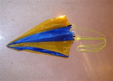
New parachute |

Detail of the glued ribbon and
shroud line |
|
|
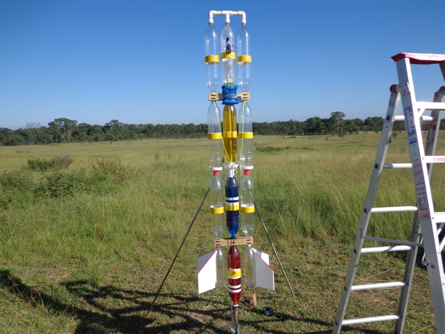
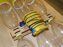
7th February
2013 - We pressure tested the 6 new
spliced pairs and re-assembled the rocket.
We added a little colour to the outside
since the parachute was going to be blue and
yellow and the water was also going to be
blue.
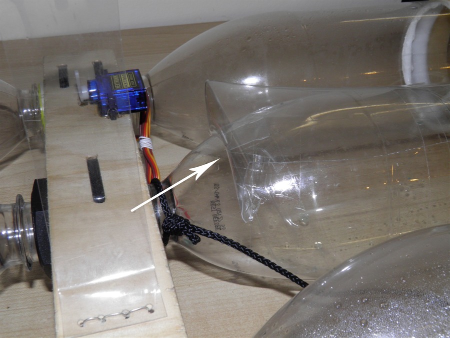
We added a small support platform under
the parachute to stop it from sliding down
during acceleration. This was just a piece
of PET bottle taped to the side of the
bottle.
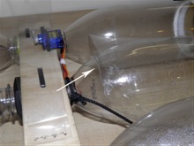
Arrow shows the support platform |
Parachute held down by door |
...and rests against the
platform |
Assembled rocket ready to fly |
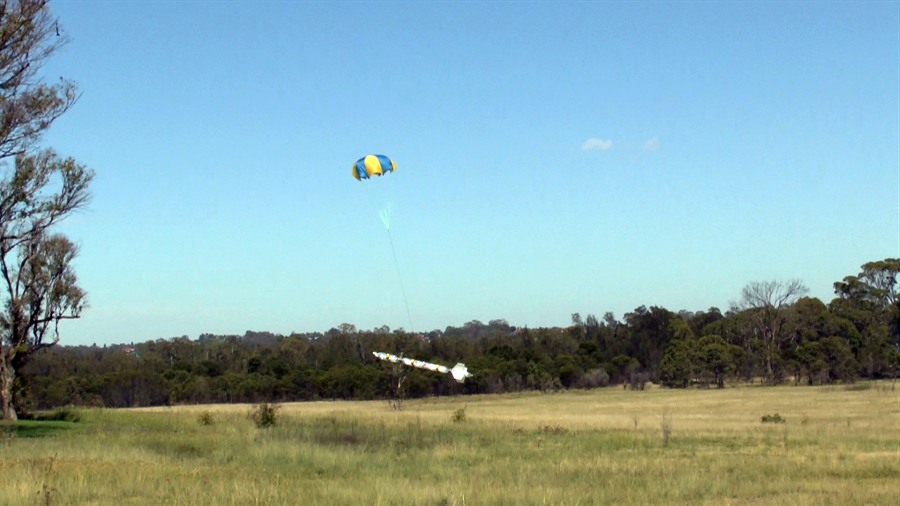
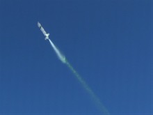
10th
February 2013 - Launch day. This time we
had a much better success. Full launch
report is here:
Day 130.
Blue food colouring |
 |
Apogee deployment |

Gentle landing |
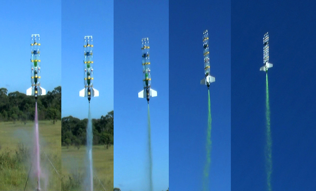
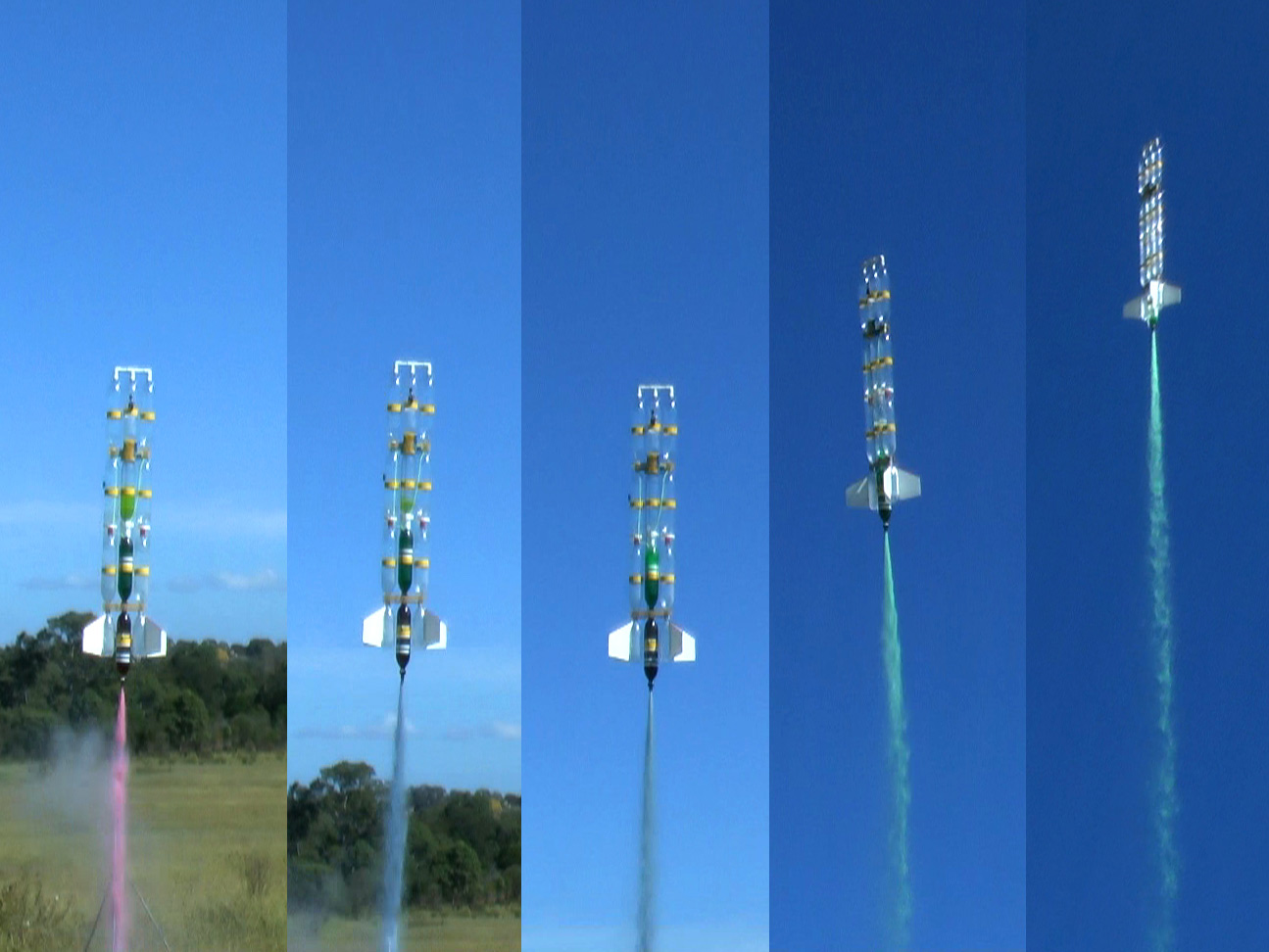
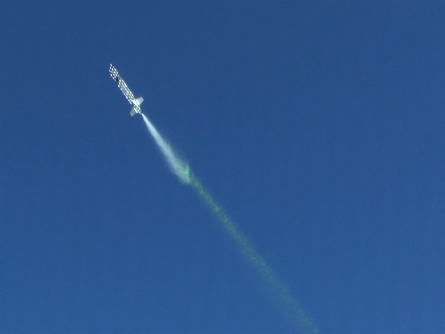
30th March
2013 - Launch day - Painting the sky.
This time we put differently coloured water
in each of the spliced pairs in order to
change the water stream colour mid flight.
See the full launch
report from day 132 for more details.
Multi-coloured |

Flight 1 |
Flight 2 |
Air-pulse during flight 1 |
|