 |
 |
![]()
![]()
![]()
|
|
last updated: 3rd May 2026 - Day 245 - Launch Tubes #3 |
|
|
|
Splicing Bottles AS#5 |
|
#235 - Coming Soon |
|
#234 - Coming Soon |
|
#233 - Coming Soon |
|
#232 - Coming Soon |
|
#196 - Coming Soon |
|
#193 - Coming Soon |
|
#172 - Coming Soon |
|
|
| FLIGHT LOG | |||||||||||||||||||||||||||||||||||||||||||||||||||||||||||||||||||||||||||||||||||||||||||||||||||||||||||||||||||||||||||||||||||||||||||||||||||||||||||||||||||||||||||||||||||||||||||||||||||||||||||||||||||||||
|---|---|---|---|---|---|---|---|---|---|---|---|---|---|---|---|---|---|---|---|---|---|---|---|---|---|---|---|---|---|---|---|---|---|---|---|---|---|---|---|---|---|---|---|---|---|---|---|---|---|---|---|---|---|---|---|---|---|---|---|---|---|---|---|---|---|---|---|---|---|---|---|---|---|---|---|---|---|---|---|---|---|---|---|---|---|---|---|---|---|---|---|---|---|---|---|---|---|---|---|---|---|---|---|---|---|---|---|---|---|---|---|---|---|---|---|---|---|---|---|---|---|---|---|---|---|---|---|---|---|---|---|---|---|---|---|---|---|---|---|---|---|---|---|---|---|---|---|---|---|---|---|---|---|---|---|---|---|---|---|---|---|---|---|---|---|---|---|---|---|---|---|---|---|---|---|---|---|---|---|---|---|---|---|---|---|---|---|---|---|---|---|---|---|---|---|---|---|---|---|---|---|---|---|---|---|---|---|---|---|---|---|---|---|---|---|
|
|||||||||||||||||||||||||||||||||||||||||||||||||||||||||||||||||||||||||||||||||||||||||||||||||||||||||||||||||||||||||||||||||||||||||||||||||||||||||||||||||||||||||||||||||||||||||||||||||||||||||||||||||||||||
| Day 171 - How to Measure Altitude | |||||||||||||||||||||||||||||||||||||||||||||||||||||||||||||||||||||||||||||||||||||||||||||||||||||||||||||||||||||||||||||||||||||||||||||||||||||||||||||||||||||||||||||||||||||||||||||||||||||||||||||||||||||||
|
Date:
14th February 2016 Location: Whalan Reserve, NSW, Australia Conditions: Calm, Blue Skies, 32C, Team Members at Event: John K, Paul K, GK,and PK. Measuring AltitudesThis week we have a look at 4 different ways to measure altitude of a water rocket. We tested all of these techniques on each launch to compare how accurate they are and then we look at the advantages and disadvantages of each.
Video
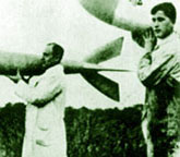
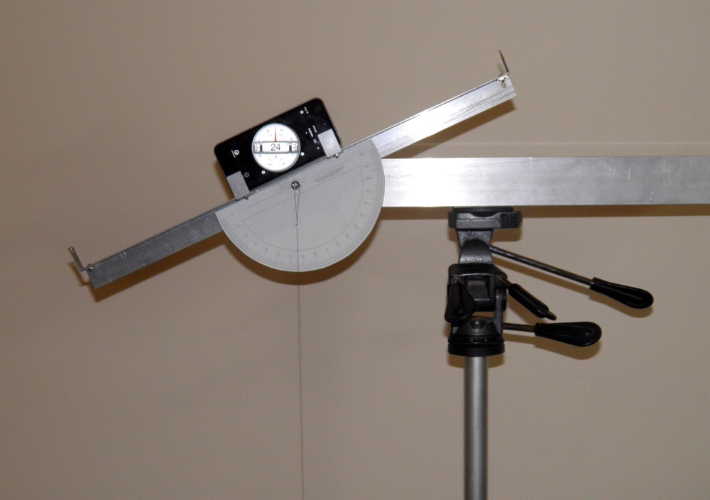
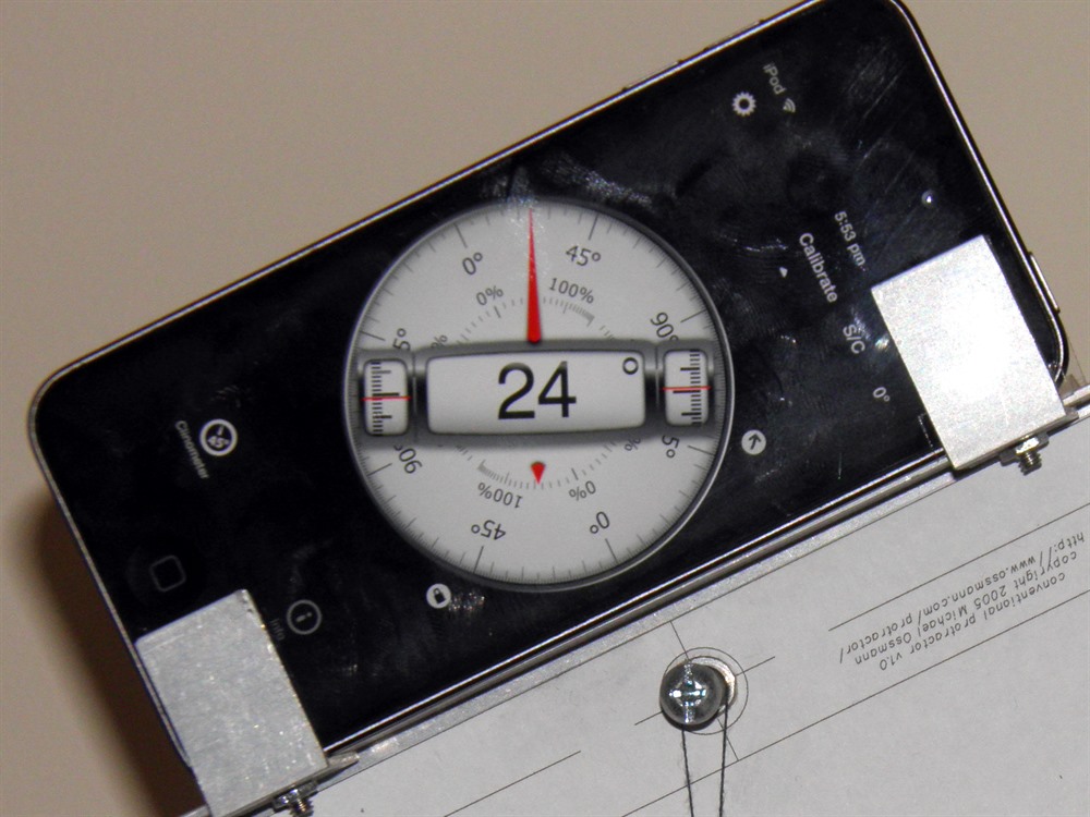
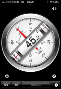
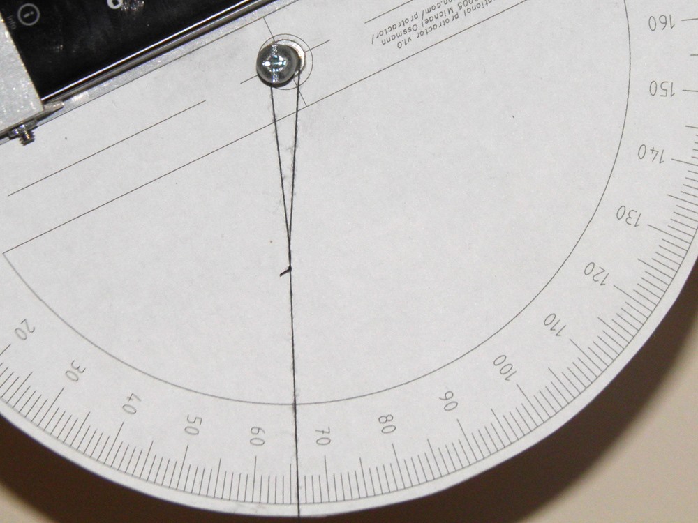
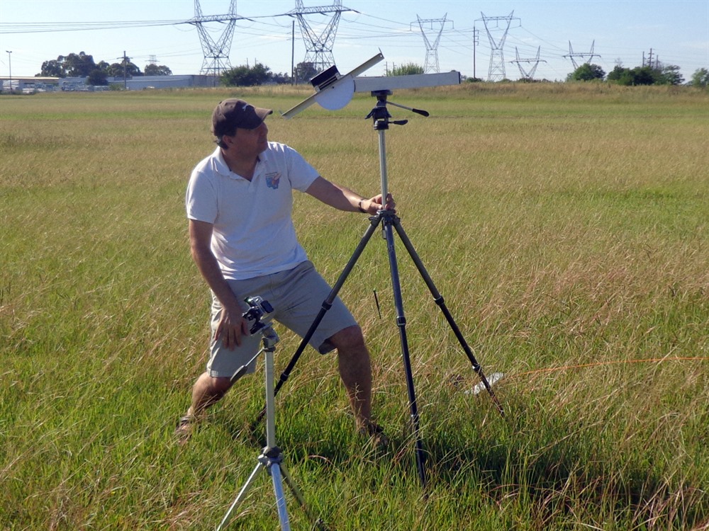
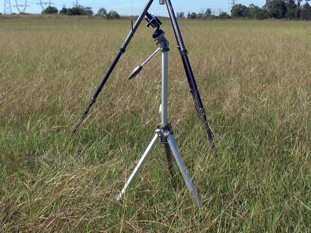
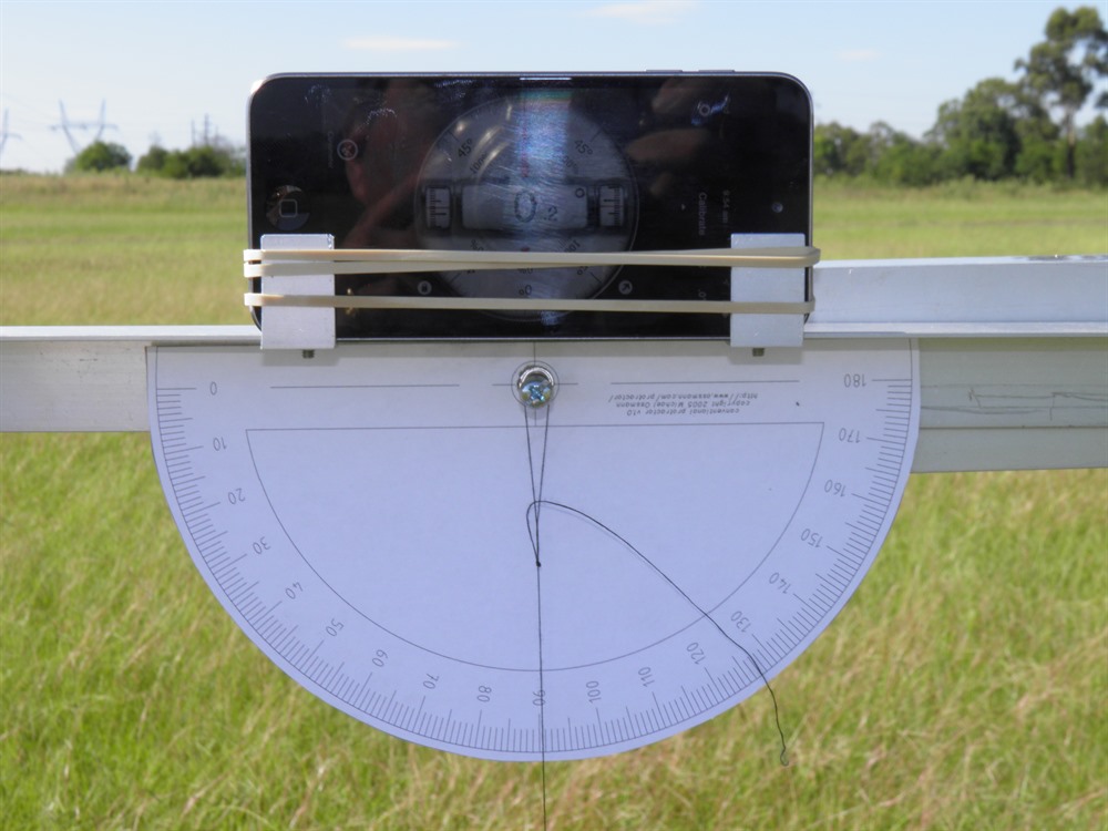
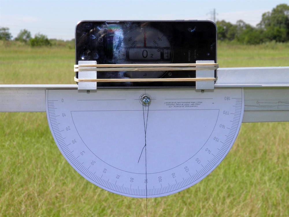
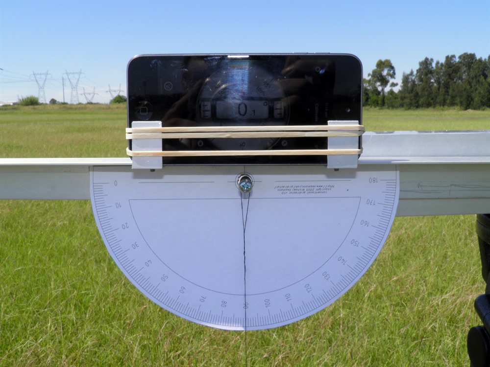
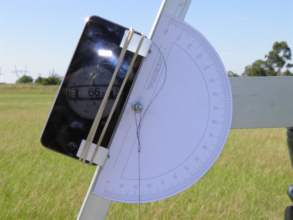
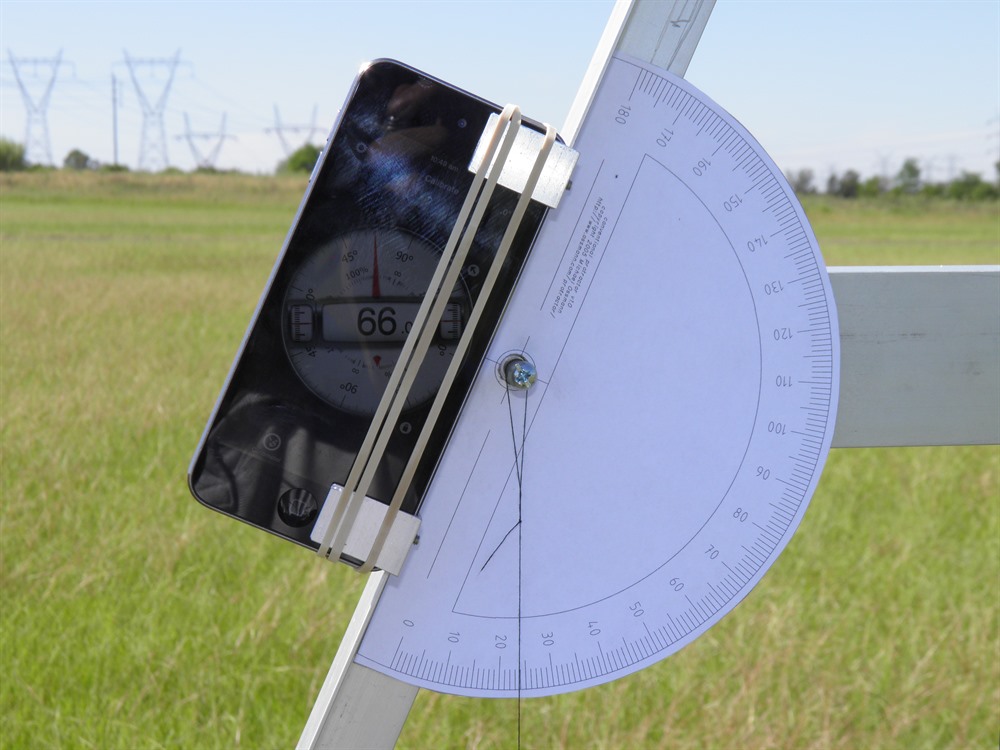
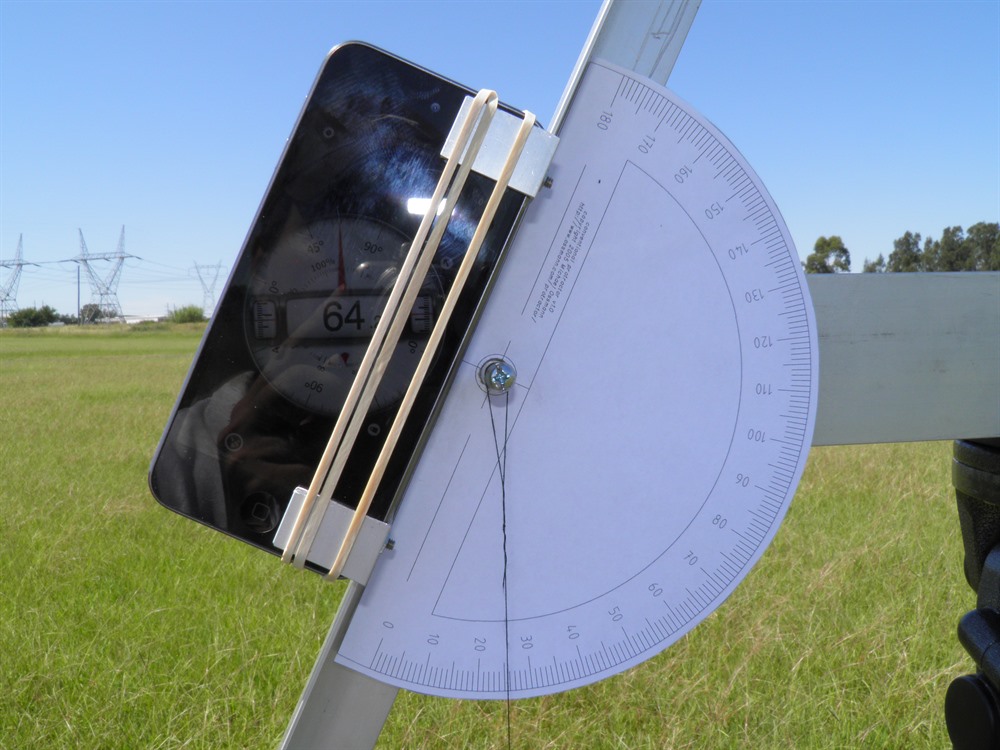
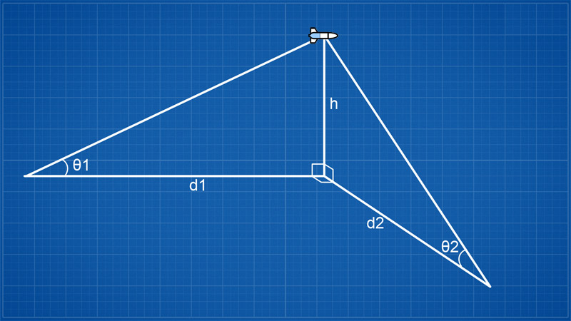
Experiment SetupInclinometerWe made the inclinometer from a couple of spare aluminium sections we had on hand. The pivot point was made with a screw and a lock nut. We put a piece of felt between the arm and the base and tightened the lock nut until there was sufficient friction to keep the arm in the set position while still allowing it to easily move. This way you could track the rocket to apogee and then at apogee you would just leave the arm in place so you could record the reading from the side. We used two different angle measuring devices. We used the classic hanging weight on the end of a thread and a protractor. We also mounted an iPod on top of the arm and used a free App that uses the internal accelerometers to measure the angle. The protractor and thread is good for about 0.5 degree accuracy while the iPod was down to about 0.1 degrees. Most smart phones today can perform the same function. The whole inclinometer could also be pivoted about the vertical axis so the rocket could be tracked laterally away from the launch pad. We would always take two readings. One with the inclinometer pointing at the nose of the rocket on the pad as that was about the same height as the inclinometer was above ground. The second reading was then recorded at apogee. The difference between these angles was used in the calculation.
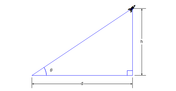
To work out the altitude we use the following formula:
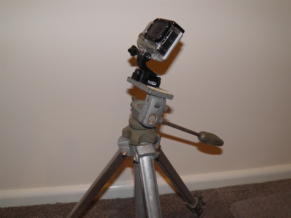
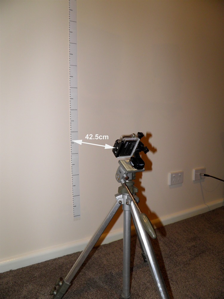
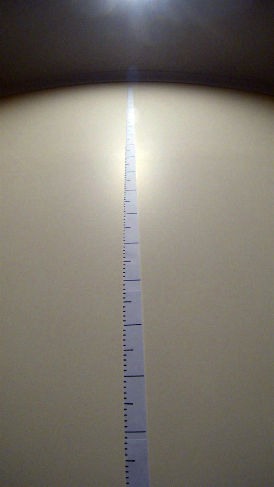
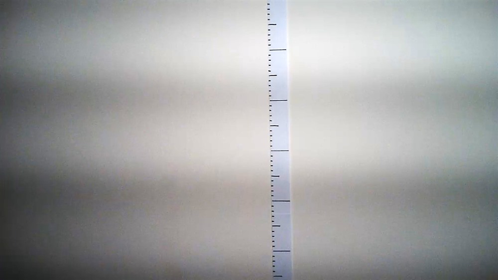
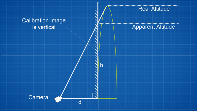
Ground PhotographyThe ground camera used in the experiment was the GoPro Hero 3 Black Edition. We set the recording format to 2.7K video with a wide setting. We chose the higher resolution format so it was easier to locate the rocket in the sky and with better precision. The camera was set up on a tripod and angled upwards at around 45 degrees. We also rotated the camera to portrait mode so we could get the most pixels vertically. This would give us enough coverage with the launcher in view near the bottom of the frame and more than 90 degrees above the camera to make sure we caught the apogee of the flight. We located the camera at the same distance from the rocket as the inclinometer. (42.5m) To get the calibration image, we placed the camera at the same angle, and 42.5cm away from a vertical wall. This would give us a 100:1 scale factor. We then placed markings up the wall and took an image with the camera with the same video settings.
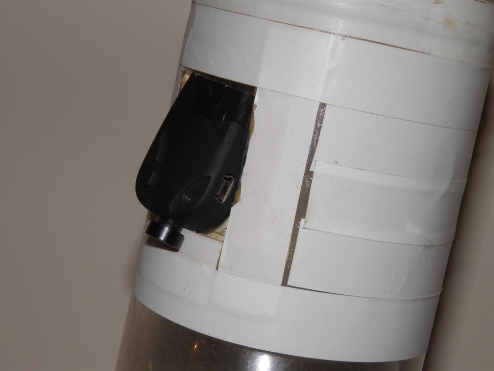
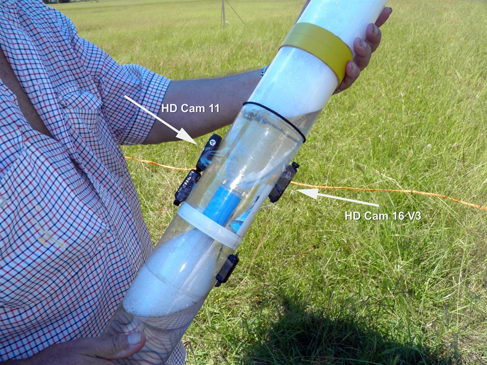
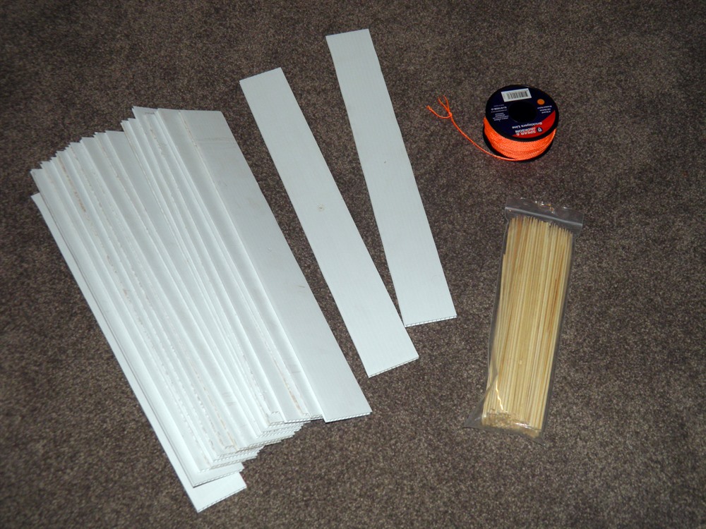
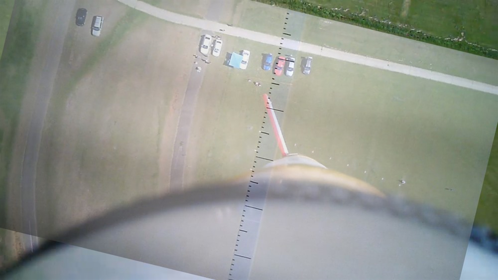
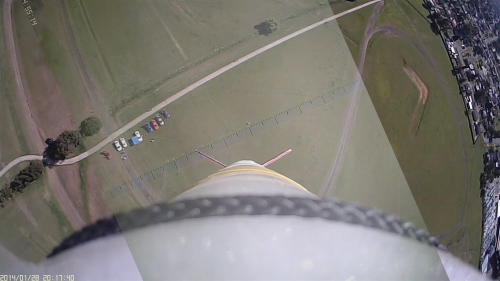
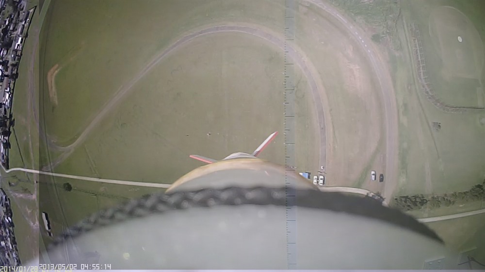
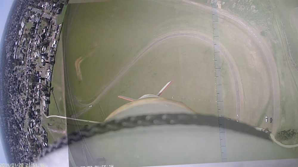
Aerial PhotographyFor this experiment we prepared a 100m string with 5m marks on it and then at the launch site we ran 50m of the string in one direction and then 50m at 90 degrees in another direction. We then placed a set of white coriflute markers at each 5m point and pinned it to the ground with a skewer stick so wind couldn't blow it away. With this setup we were hoping that at least some of the markings would be visible from the air at apogee. We used two different cameras taped to either side of the rocket. One camera had a regular narrower field of view while the other had a wide angle lens. We again obtained a calibration image for each camera, but this time we located the camera exactly 1m from the wall.
To work out the altitude we simply use ratios of the measurements in the apogee photo vs the calibration image measurements. For example if in the apogee image we see that 35m on the ground corresponds to 30cm in the calibration image then we can use the following formula to work out how high we are:
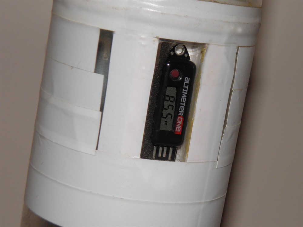
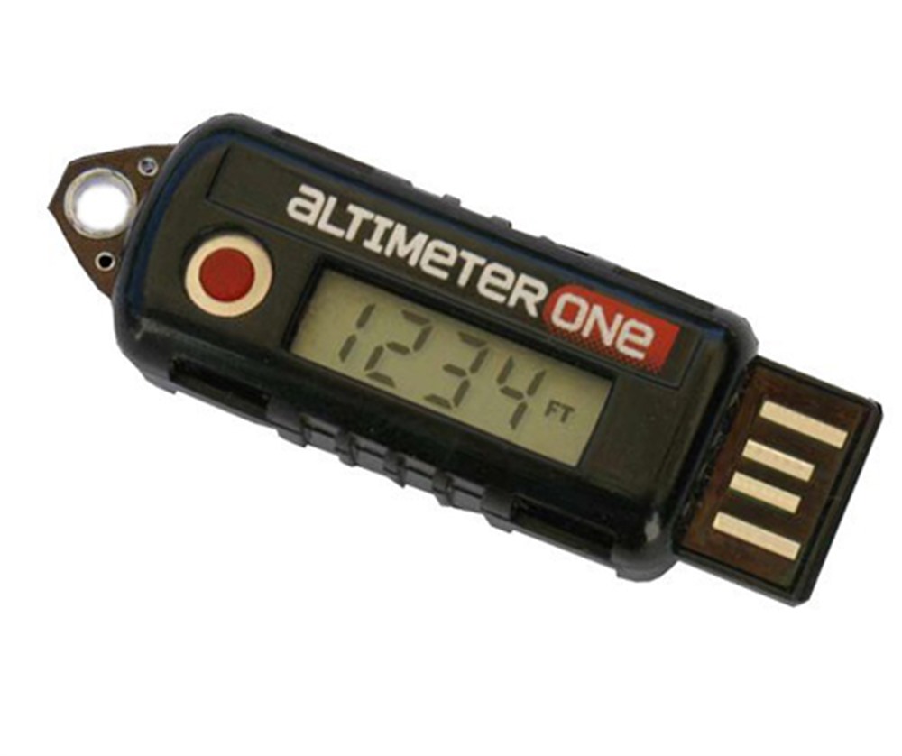
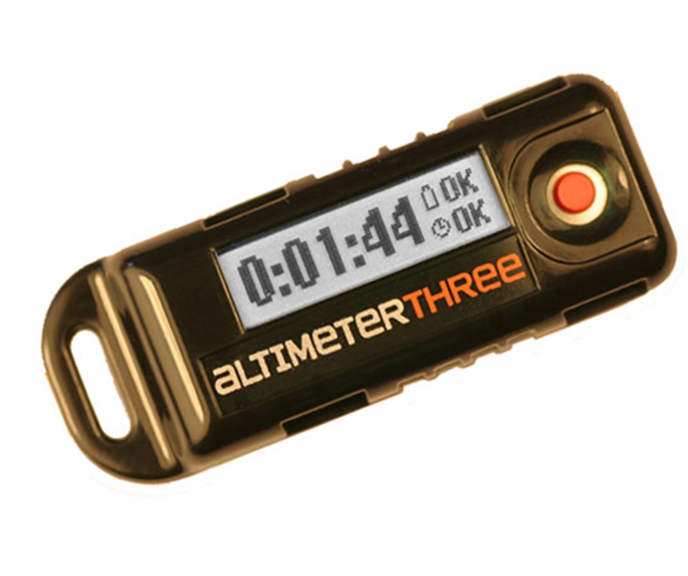
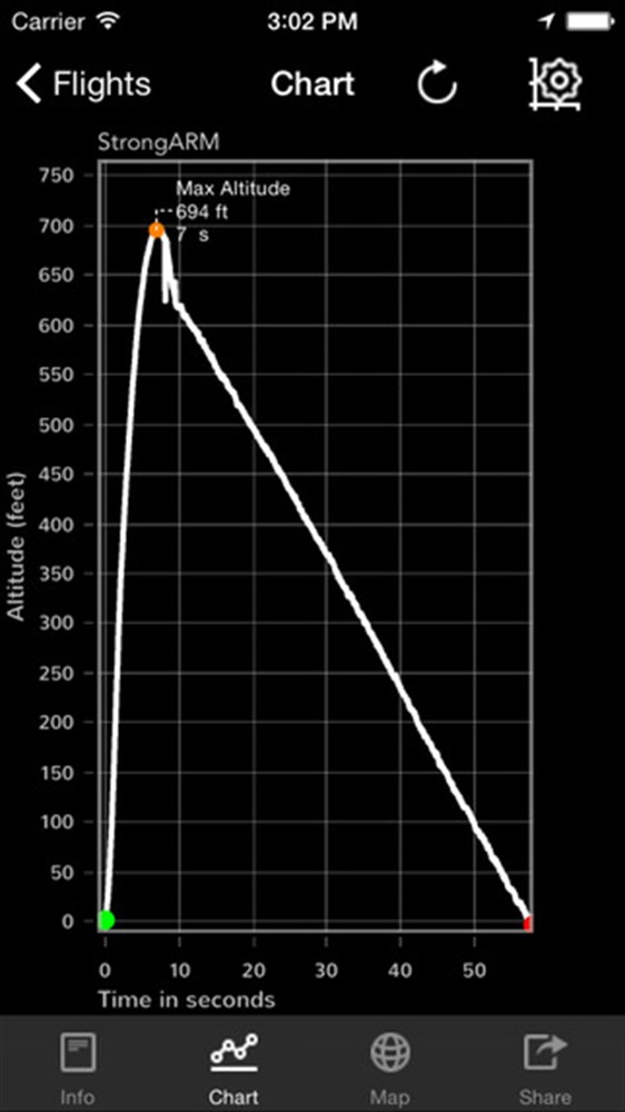
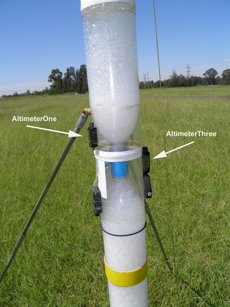
AltimetersWe used two different altimeters for these flights The peak only reading AltimeterOne and the recording AltimeterThree. These altimeters use barometric pressure sensors to measure altitude down to an accuracy of about 1 foot.
ResultsWe repeated the experiment on three flights and measured the altitude using all 4 techniques on each flight. Inclinometer ResultsThe following angles were observed with the two different inclinometers. They were in quite close agreement with each other. The table also shows the calculated altitude estimate based on the average of the two angles. The inclinometer was located 42.5 meters from the launch pad.
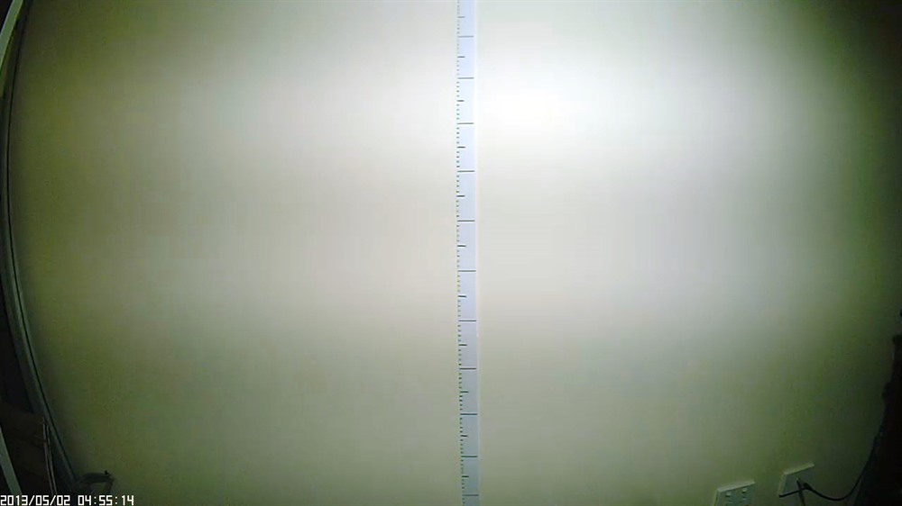
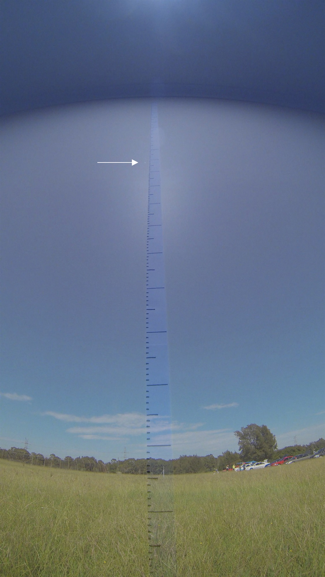
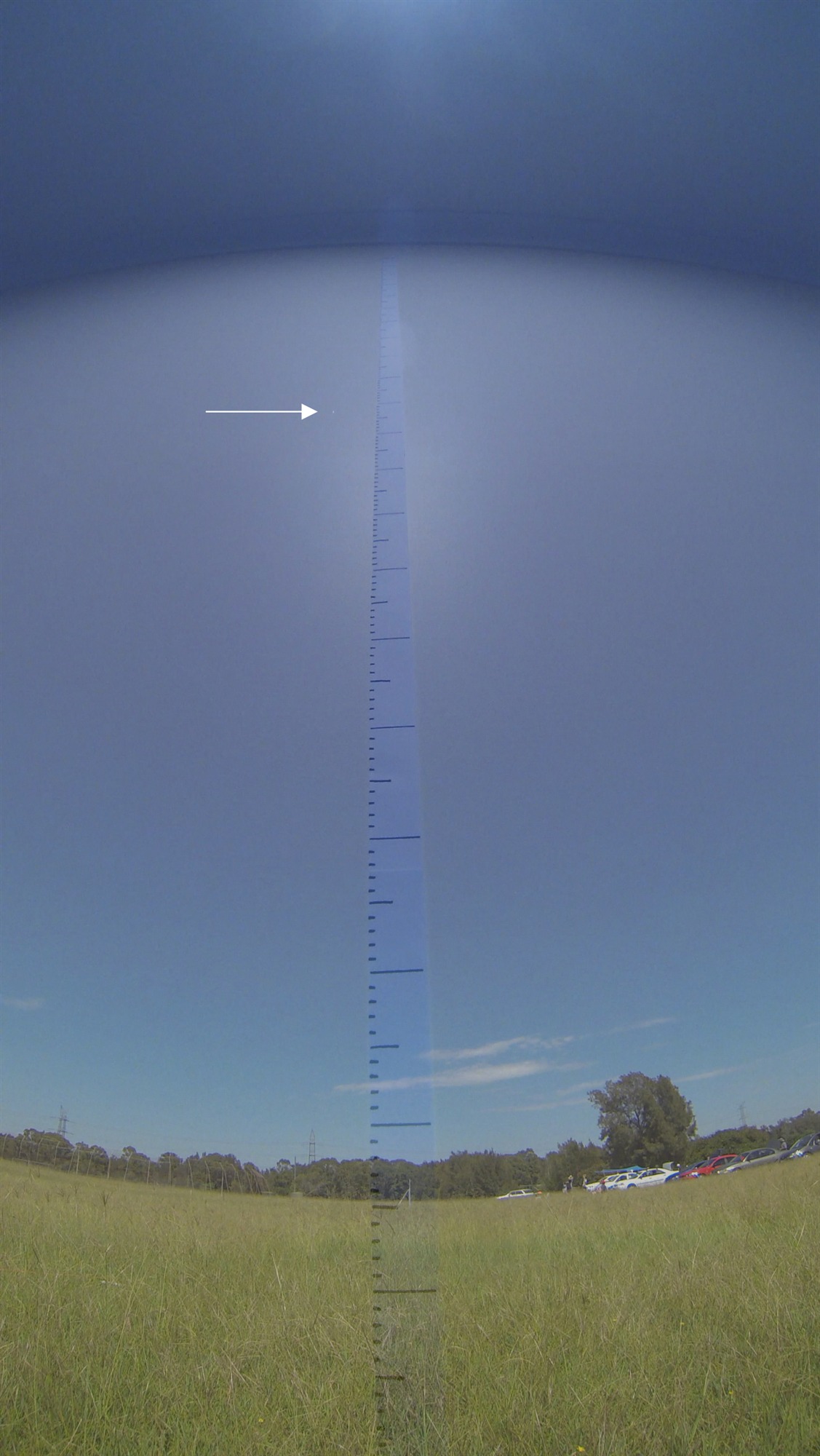
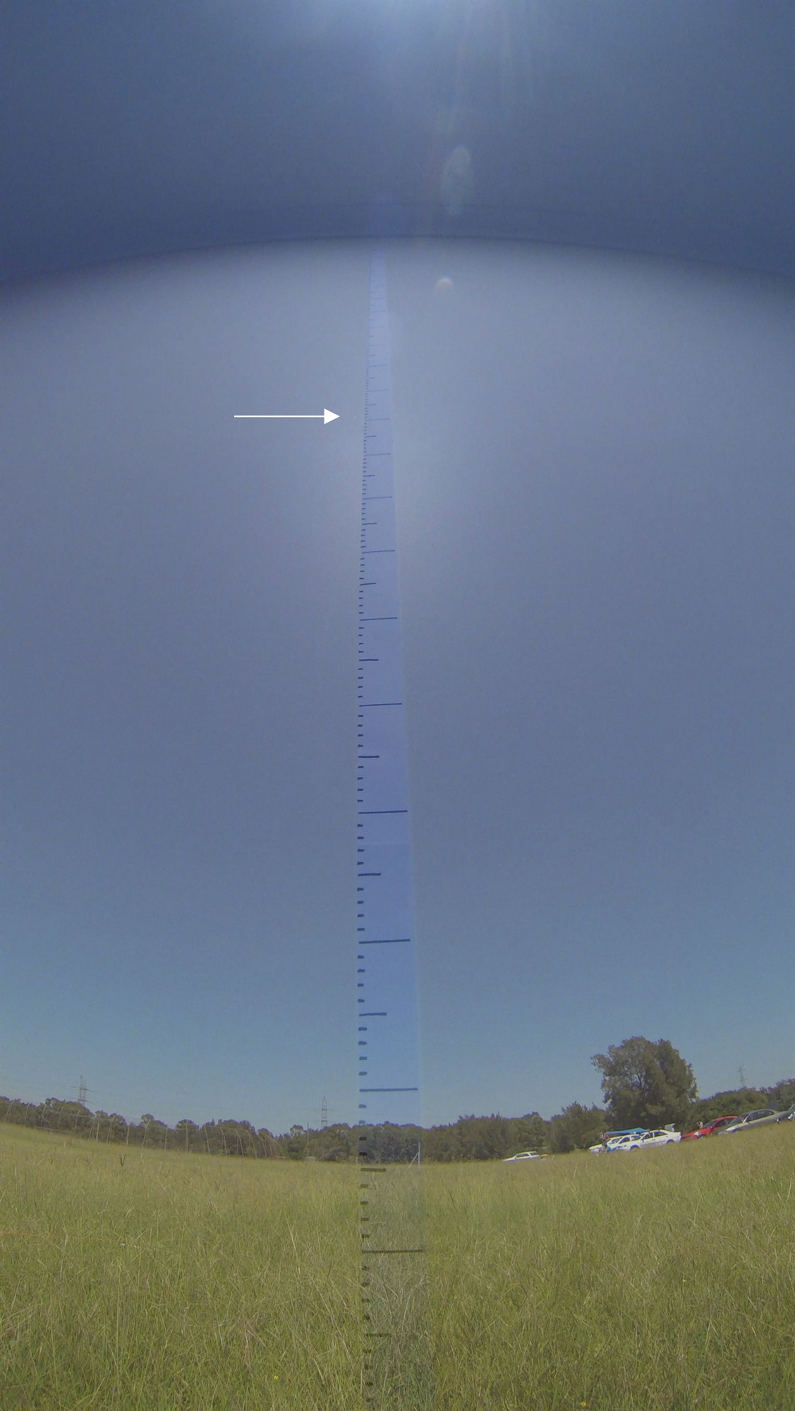
Ground Photography ResultsTo find the apogee image we watched the flight video frame by frame and paused when the rocket stopped gaining altitude. We then saved this frame to a file. We then overlayed this image with the calibration image and read the altitude off directly. Each small tick mark represents 1 meter in the images below.
After combining the calibration image with the apogee image we arrived at the following altitude estimates:
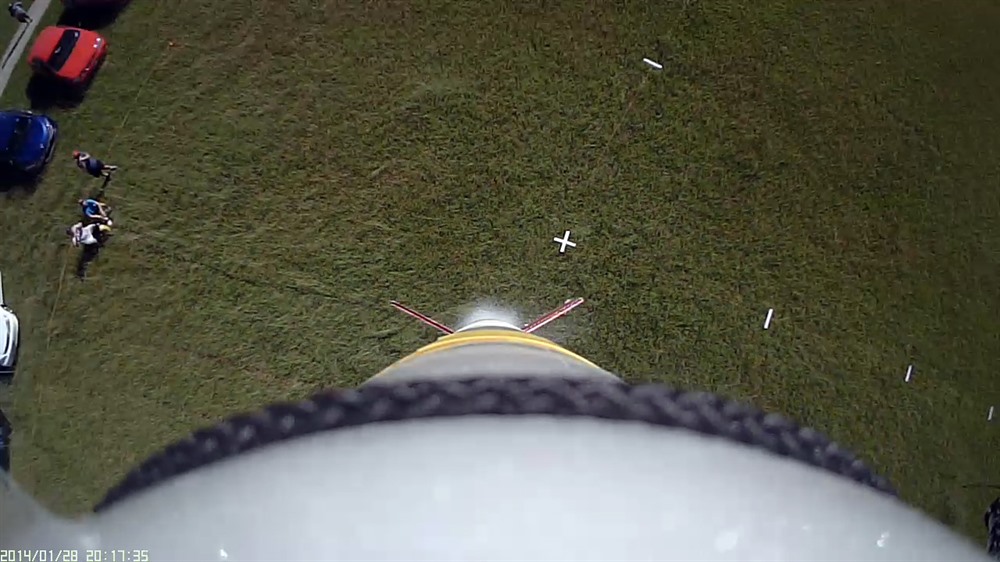
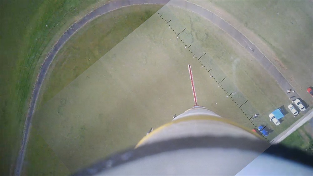
Aerial Photography ResultsThe markers on the ground were easily visible in the footage right near apogee. Having the two sets of markers at 90 degrees helped ensure that at least one set wasn't obscured by the rocket. We again reviewed the video for each flight and saved an image when the rocket was near apogee and the ground markers were visible. The narrow FOV camera failed to record the entire flight of Flight #3.
After overlaying the calibration image and rotating it to align with the ground markers we were able to work out the altitude by scaling the readings appropriately. Here are the altitude estimates from the two cameras. The estimates in brackets represent altitude derived from the second set of markers placed at 90 degrees. These are higher because the camera is looking at them from an angle, ie. not directly above them,
Altimeter ResultsWe flew the AltimeterOne on all three flights, and the AltimeterThree was added on the last flight. We know from past experiments that these are quite accurate, and so we used these readings as the reference for the other measurement techniques.
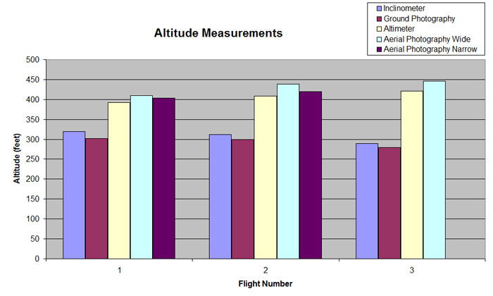
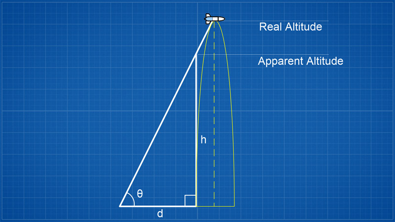
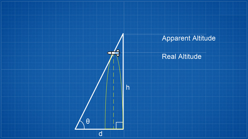
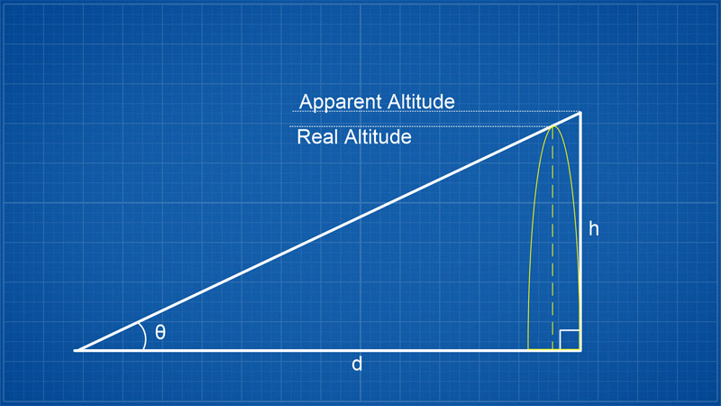
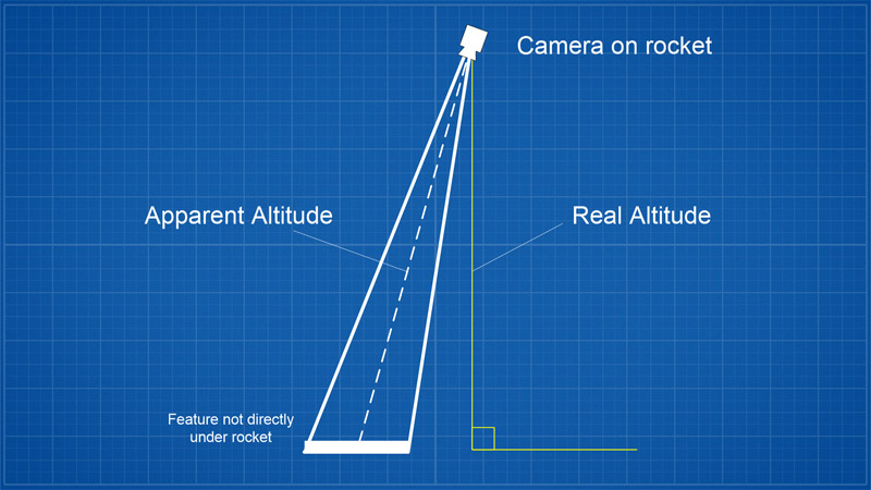
AnalysisHere is a summary of the measurements. As you can see the inclinometer and ground camera photography have a significant errors in their estimates. This is primarily due to non-vertical flight of the rocket. On the diagram below you can see that if the rocket reaches apogee some distance away from the vertical the apparent elevation angle is not going to correctly represent the true picture. For large elevation angles this error is going to be even more significant.
ConclusionAs we can see each of the different techniques produced different altitude estimates for the same flight. When compared to the altimeters the Inclinometer results varied by as much as 30% from the actual altitude. The ground photography technique achieved similar results, while the aerial photography was a little better. If you are performing experiments where it is very important to measure altitude accurately then altimeters are really your only option, When flying casually and you just want to know approximately how high your rocket went then the other techniques could be used. Let's have a look at some of the advantages and disadvantages of using each of the techniques.
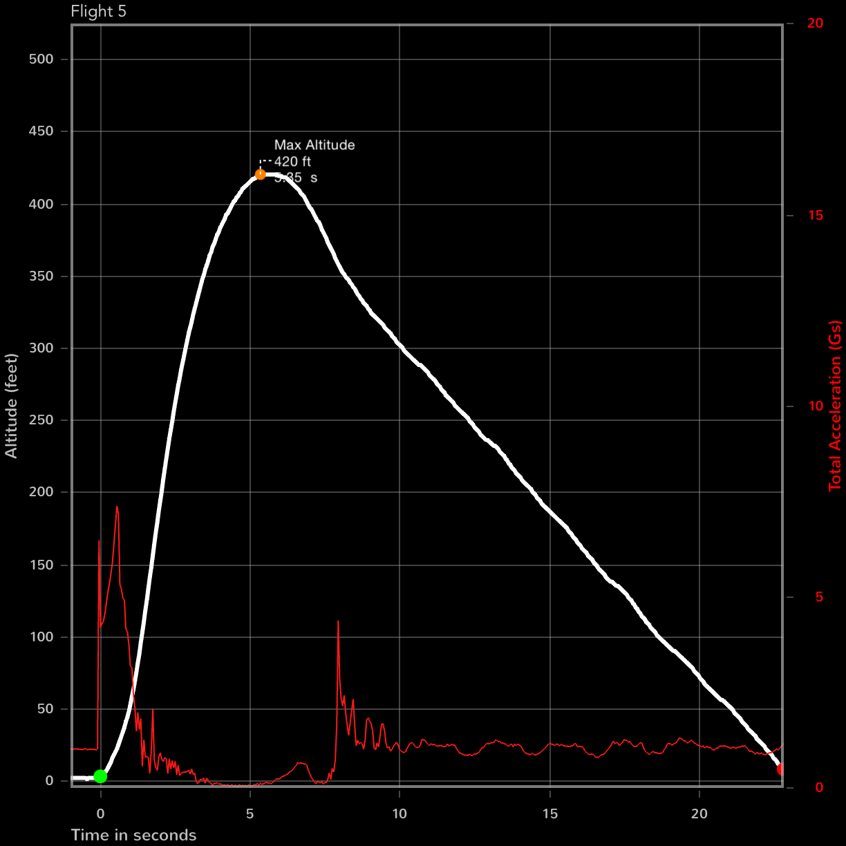
Flight Details
|
|||||||||||||||||||||||||||||||||||||||||||||||||||||||||||||||||||||||||||||||||||||||||||||||||||||||||||||||||||||||||||||||||||||||||||||||||||||||||||||||||||||||||||||||||||||||||||||||||||||||||||||||||||||||