last updated: 21st october 2023 - Day 226 to Day 230 - Various Experiments

Safety First

Search

Site Index

Tutorials

Articles

Rocket Gallery

Labs

Where To Buy

10 Challenges

Links

Blog

Glossary

Contact Us

About


Construction - Basic

Body

Ring Fins

Flat Fins

Nozzle

Nosecone

Construction - Advanced

Robinson Coupling

Splicing Bottles #1

Splicing Bottles AS#5

Reinforcing Bottles

Side Deploy #1

Side Deploy #2

Mk3 Staging Mechanism

Multi-stage Parachutes

Fairings

Construction - Launchers

Gardena Launcher

Clark Cable-tie

Medium Launcher

Cluster Launcher

Launch Abort Valve

Quick Launcher

How It Works

Drop Away Boosters

Katz Stager Mk2.

Katz Stager Mk3.

DetMech

Dark Shadow Deployment

Articles

Recovery Guide

Parachutes

How Much Water?

Flying Higher

Flying Straight

Building a Launcher

Using Scuba Tanks

Nozzles

Video Taping Tips

MD-80 clone

Making Panoramas

Procedures

Burst Testing

Filling

Launching

Recovery

Electronics

Servo Timer II

V1.6

V1.5

V1.4

V1.3, V1.3.1, V1.3.2

V1.2

Deploy Timer 1.1

Project Builds

The Shadow

Shadow II

Inverter

Polaron G2

Dark Shadow

L1ght Shadow

Flight Log Updates

#230 - Tajfun 2 L2

#229 - Mac Uni AON

#228 - Tajfun 2 Elec.

#227 - Zip Line

#226 - DIY Barometer

#225 - Air Pressure Exp.

#224 - Tajfun 2

#221 - Horizon Deploy

#215 - Deployable Boom

#205 - Tall Tripod

#204 - Horizon Deploy

#203 - Thunda 2

#202 - Horizon Launcher

#201 - Flour Rockets

#197 - Dark Shadow II

#196 - Coming Soon

#195 - 3D Printed Rocket

#194 - TP Roll Drop

#193 - Coming Soon

#192 - Stager Tests

#191 - Horizon

#190 - Polaron G3

#189 - Casual Flights

#188 - Skittles Part #2

#187 - Skittles Part #1

#186 - Level 1 HPR

#185 - Liquids in Zero-G

#184 - More Axion G6

#183 - Axion G6

#182 - Casual Flights

#181 - Acoustic Apogee 2

#180 - Light Shadow

#179 - Stratologger

#178 - Acoustic Apogee 1

#177 - Reefing Chutes

#176 - 10 Years

#175 - NSWRA Events

#174 - Mullaley Launch

#173 - Oobleck Rocket

#172 - Coming Soon

#171 - Measuring Altitude

#170 - How Much Water?

#169 - Windy

#168 - Casual Flights 2

#167 - Casual Flights

#166 - Dark Shadow II

#165 - Liquid Density 2

#164 - Liquid Density 1

#163 - Channel 7 News

#162 - Axion and Polaron

#161 - Fog and Boom

#1 to #160 (Updates)


WATER ROCKET - FLIGHT COMPUTER
This section describes the details of the water rocket flight computer (FC) as designed by the Air Command team.

The purpose of the FC is to co-ordinate various events during the flight of a water rocket. One of its responsibilities is to deploy the parachute at the desired time.

Version 1.3
The circuit diagram.
Two V1.3 FC have been built to be used in our up coming rockets.
The 6V battery is now mounted under the PCB so that the FC can be mounted close to the rocket body skin.
Side view of the FC.
This is a photo showing the orientation of FC within the nosecone. It has to be mounted this way to let the launch detect switch work.
The launch detect switch is just a microswitch with a nail that is free to move within the straw guide glued to the PCB. The launch detect G-force can be adjusted by adjusting the length of the nail.


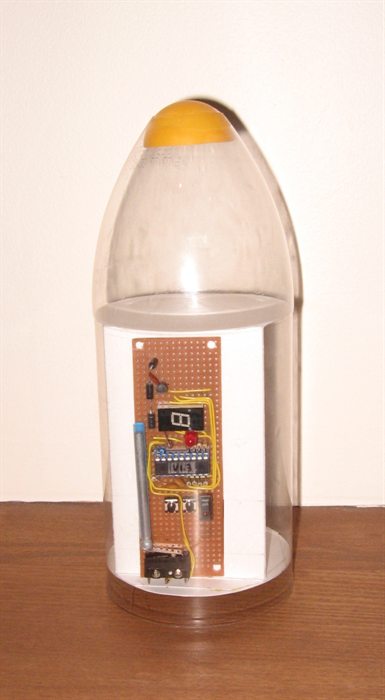
V1.3 is the next iteration of our water rocket flight computer. While in general retaining the same functionality as V1.2 the following changes have been made:
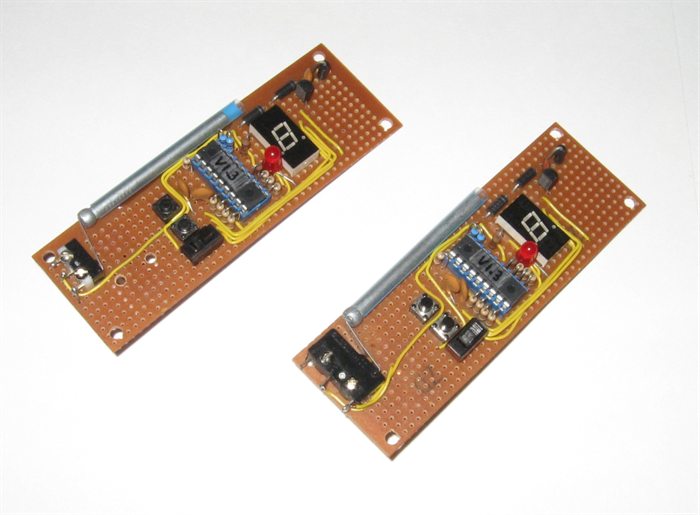
  • Single rectangular board design. This makes it simpler for manufacture and mounting.
  • Single power supply. The processor and actuator run from a single 6V battery now.
  • Modified launch detect switch.
  • Opto-coupler has been removed
  • Larger higher brightness "Armed" LED to make it easier to see in daylight.
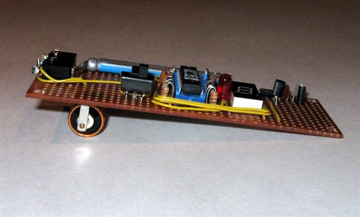
  • Reduced overall weight. ( 37 g  - including battery )
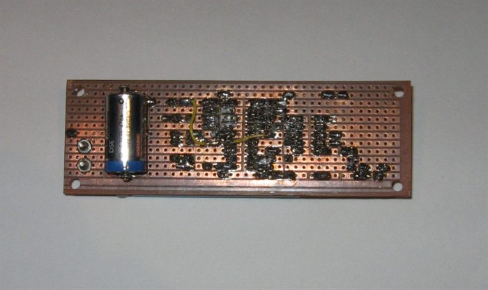
  • Battery attached to the PCB.
  • Actuator moved to the release mechanism.
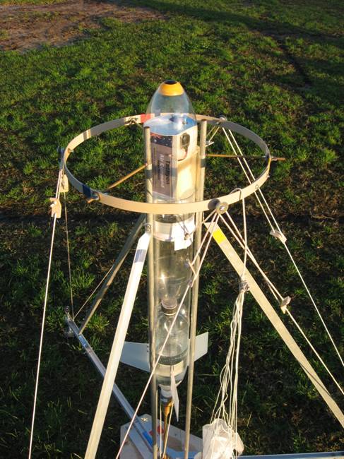
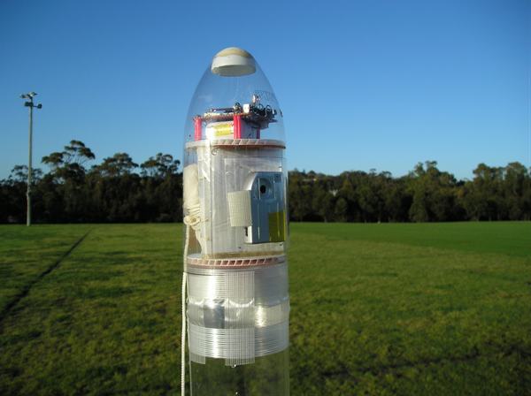
  • Designed to be mounted in 90mm as well as 110mm diameter rocket bodies.

Design

The design changes were primarily chosen to improve weight of the system. The majority of weight savings were due to having a single board design, switching to single battery operation and mounting the battery directly on the PCB. Other small weight improvements included the use of smaller components.

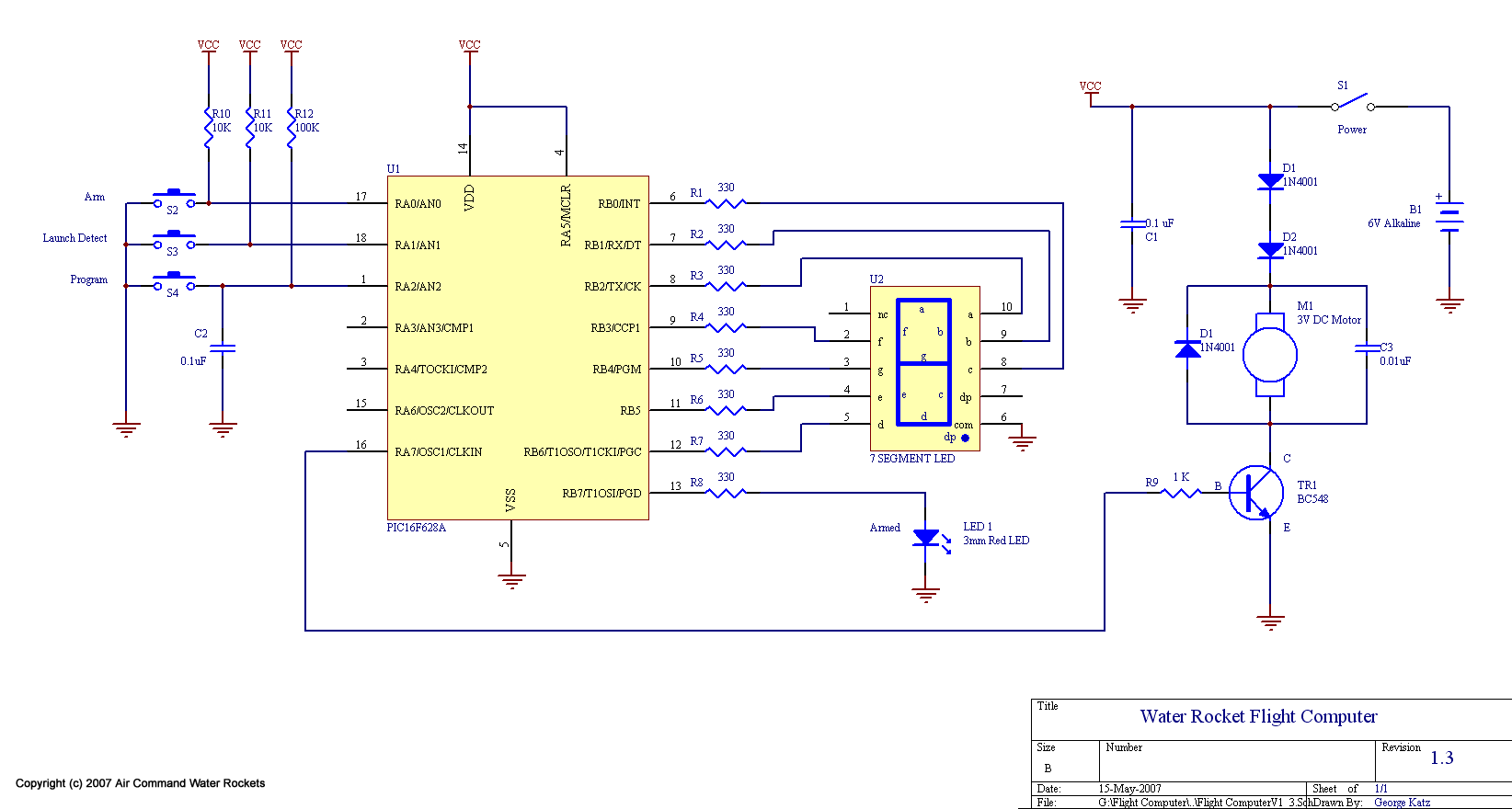
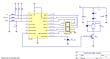
The opto-coupler has been removed and the micro-controller directly drives the actuator transistor. A snubber diode has been added across the motor as well as a small capacitor to reduce noise. A capacitor has also been added across the micro-controller's power rails.

The software changes included disabling the brown-out reset on the micro-controller to prevent it from resetting when there was a bit of noise on the power rails. The "P" display during parachute deployment has been replaced with a "-" to reduce the amount of power drawn from the battery while the motor is in operation.

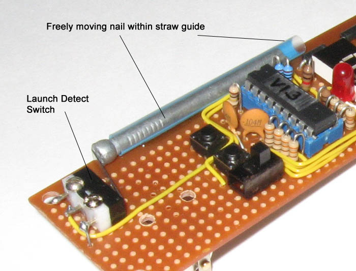
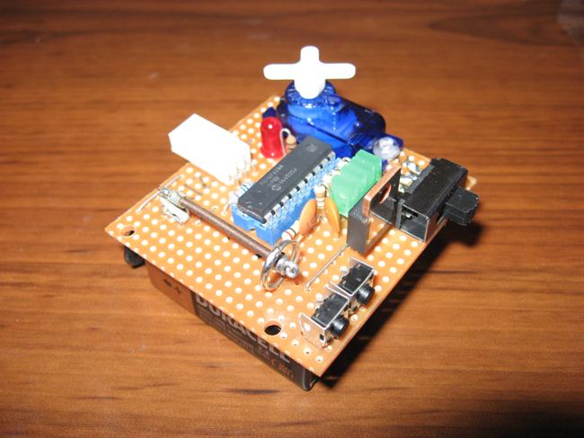
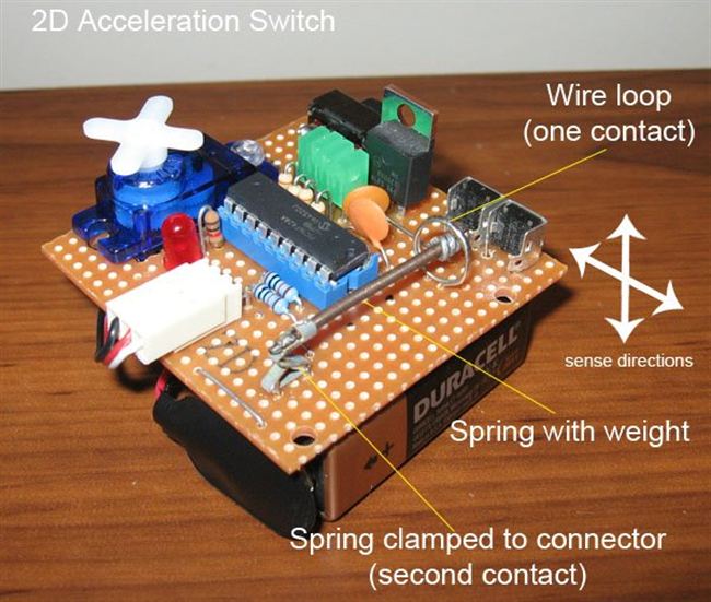
The launch detect switch is a smaller micro-switch and is activated by a large nail that slides within a guide. This helps prevent unnecessary shocks on the armature during landing. With the weight glued to the armature in V1.2 it was possible for the armature to pop out of the switch on landing. The new arrangement is also more compact.

The "power", "program" and "arm" switches have all been placed close together to allow them to be accessible from a much smaller hole in the rocket body. This helps streamline the rocket reducing drag.

Due to upcoming experiments the range of selectable delays has also been increased. The following table gives the range of delays settable with version 1.3.

LED Display Deploy Delay
(Seconds)
0 3
1 3.25
2 3.5
3 3.75
4 4
5 4.25
6 4.5
7 4.75
8 5
9 5.25
A 5.5
b 5.75
C 6
d 6.25
E 6.5
F 6.75
G 7
h 7.25
i 7.5
J 7.75
k 8
L 8.25
m 8.5
n 8.75
o 9
P 9.25
q 9.5
r 9.75
S 10
t 10.25
U 10.5
v 10.75
w 11


Operation

Operation is identical to that of version 1.2. Refer to this section for more details.

Software

The assembly source code can be found here: Flight1_3.asm

The assembled HEX code can be found here: Flight1_3.HEX

Back to top

Version 1.3.1
The circuit diagram.
V1.3.1's maiden flight on board Tachyon.


V1.3.1 is an adaptation of V1.3 to drive an RC micro-servo motor instead of the DC motor used by V1.3. The reason for switching to the RC motor was reliability and simplicity. Although the RC motors are a little heavier, by about 4 grams, they are self contained, and easy to mount.

The PIC can drive the RC PWM signal directly and therefore does not need the DC motor driver circuit, further simplifying the design.

The other design change has been the addition of a 7806 voltage regulator. This allows the flight computer to run from 9V or 12V batteries. We are using 9V batteries for most flights. Although considerably heavy, at 46 grams, the 9V batteries are easy to mount, cheap, available everywhere and provide plenty of current capacity for lots of regular flights. For record setting flights where weight is a premium, we will use much lighter batteries that may only last a few flights.

To date V1.3.1 has flown 18 times. (updated 15th April 2008 - includes day 58)
= 15 successful deploys
= 1 faulty rocket takeoff, crashed shortly after takeoff (flight computer not at fault)
= 2 non-deploy, reason unknown possibly faulty servo in one? (flown as sustainer with very high G takeoff.)

Operation

Operation is identical to that of version 1.3.

Software

The assembly source code can be found here: Flight1_3_1.asm

The assembled HEX code can be found here: Flight1_3_1.HEX

Back to top

Version 1.3.2
V1.3.2 circuit diagram.
V1.3.2 detail
V1.3.2 detail. (9V battery)
V1.3.2 ready for maiden flight. flown with two lithium CR123A batteries.


V1.3.2 is the next iteration of the V1.3 series flight computers to reduce the weight and provide a smaller footprint.

There are a number of improvements over version V1.3.1:

  • The flight computer has a new launch detect switch which allows it to work in two dimensions. This allows the PCB to be mounted in a range of orientations. (See photo on left) The spring is the compressed type which prevents it from oscillating while handling the rocket or there is slight vibration on the launch pad after the system has been armed.
  • The servo is mounted directly to the PCB.
  • The 7 segment LED display has been replaced with 4 green rectangular LEDs. These indicate in binary. This reduced the complexity and resulted in a more compact design.
  • You can set one of 16 delays, starting at 3 seconds and incrementing in .25 second intervals to 7 seconds.
  • Now typically uses 2 x CR123A lithium batteries for reduced weight, although can run from a 9V battery.
  • The flight computer with the servo now weighs 29 grams (without battery).

To date V1.3.2 has flown 29 times. (updated 15th April 2008 - includes day 58)
= 27 successful deploys.
= 2 failed deploys.

Operation

The basic operation is the same as V1.3.1.

Software

The assembly source code can be found here: Flight1_3_2.asm

The assembled HEX code can be found here: Flight1_3_2.HEX

Back to top


Copyright © 2006-2023 Air Command Water Rockets

Total page hits since 1 Aug 2006: