The idea behind the drop away boosters is to increase the
launch velocity of the main
rocket to achieve a greater
altitude. When the stored energy
in the boosters is spent they automatically separate from the main stage
and take away their dead weight and drag.
This rocket configuration is not considered a 2 stage rocket
as the main stage and boosters all fire at the same time at
launch. The technique presented here is one we have used with success
on numerous flights.
Basic Concept
The boosters are loosely attached to the main stage and in such a
way that they can only move backwards. On launch the boosters'
greater thrust allows them to remain in place until they burn
out and drag pushes them
backwards separating them from the main stage. This
way the boosters individually fall off at exactly the right
time, irrespective of what the other boosters are doing.
Practical Implementation
Several key aspects must be maintained if this system is to
work effectively.
The boosters must produce more thrust than the main stage.
This can be achieved with either bigger nozzles, or higher
pressure than the main stage. (Use of foam
can also be used to reduce and prolong the thrust of the main
stage.)
The boosters and main stage need to be released
simultaneously.
Each boosters' thrust profile must match the thrust of
the other boosters throughout their
flight. This means the pressure, water volume and capacity has
to be equal for each booster.
Booster Capacity
The booster capacity can be made equal by using identical
bottles and construction techniques to make them.
Simultaneous Release
Different mechanical configurations can be used to simultaneously
release all the nozzles. The nozzles of both the main stage and
boosters can be held individually and released at the same time,
or only the main stage nozzle needs to be held
down, with the boosters held down by the main stage.
Equal Thrust
Equal amounts of water are easily achieved with the use
of a
measuring jug.
To equalize the pressure between the boosters is a little
more tricky. Consider the case where a manifold simply connects
the boosters together to a common air supply. What happens is that an uneven amount of
air will flow into each booster. This uneven pressure then
starts forcing the water from one booster into the other through
the manifold in order to equalize. (We found this out the hard way :) )
You could potentially rectify this situation with use of
non-return valves for each booster, but you still may end up
with a pressure difference
between the boosters. This is because the non-return valves may not close at exactly
the same pressure. The method presented here connects the air chambers
of the boosters together
through an open air manifold that only transfers air and not water.
While it is feasible to have small hoses connecting
together the air
chambers in the tops
of the boosters the boosters would remain connected
when they drop off. The hoses could catch on the fins of the
main stage, as well as preventing individual boosters from falling off
when
they stop producing thrust. One could make an
air manifold on the rocket where the hoses separate, but this
adds unnecessary complexity and weight to the rocket. Any separating mechanism has to be able to
withstand the full
pressure while on the pad.
For this reason we suggest building a simple air manifold
into the launcher. In order to achieve this, each nozzle seat
needs an air fill tube that goes through the nozzle and emerges
above the booster's water level.
How It Works
For illustrative purposes the diagrams below have been simplified
to include only the relevant components. Click on the diagrams
for a larger version.
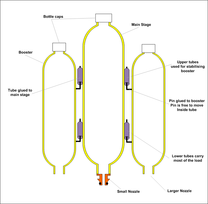
In this example the boosters and main
stage are made from spliced bottles so that they have an
opening at the bottom for the nozzle and an opening at
the top for filling with water.
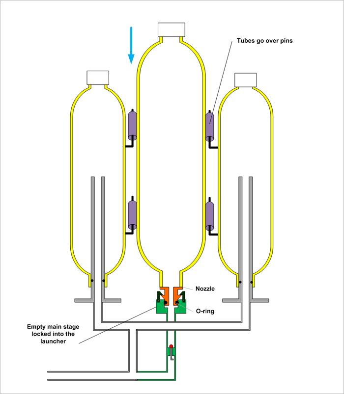
The tubes on the side of the main
stage are glued to the surface of the bottle with PL
premium glue.
The pins on the boosters are also glued to the
surface of the boosters with PL premium glue.
In this example the booster nozzles are larger than the main
stage nozzle.
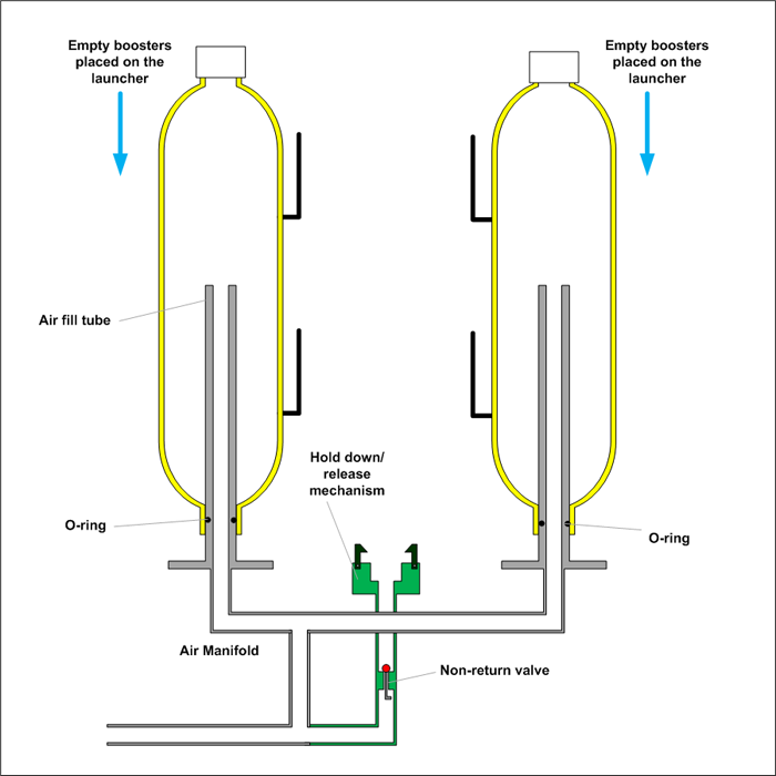
The boosters are placed on the launcher
first. These slide over the air fill tubes and seal at
the bottom with an o-ring. For illustration the booster
nozzles here are just the full bore bottle neck.
Also not shown
is the stop that prevents the booster dropping
too low.
Note that the boosters are not locked down in any
way, they are free to move up and down on the air fill
tube.
Next the main stage is placed on the
launcher carefully aligning the tubes on the main stage
with the pins on the boosters.
The main stage nozzle is locked into the central
release mechanism such as a Gardena release head.
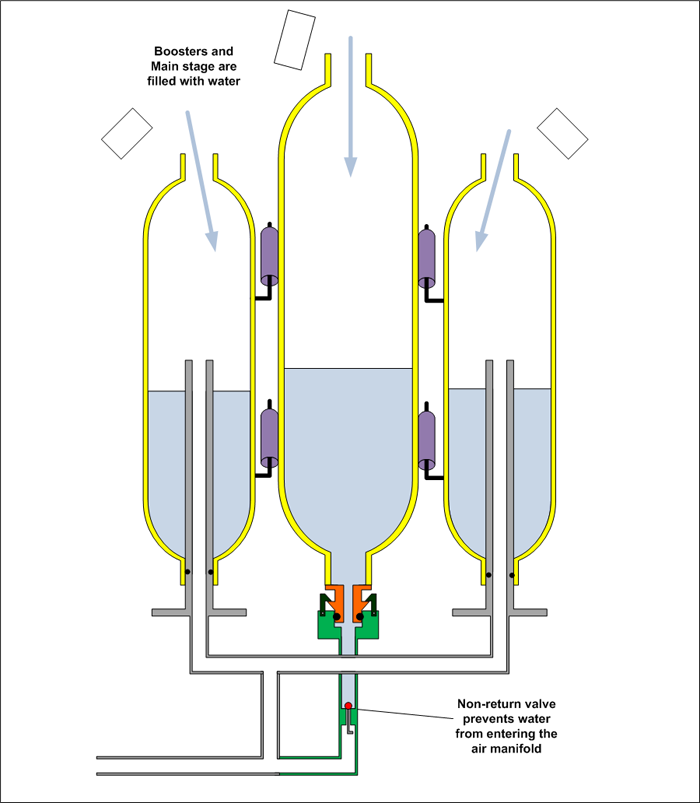
The boosters and main stage are filled
with water from the top.
Water is poured into the boosters so that it does not
go down the air fill tubes. Equal quantities of
water go in each booster.
The tops of the air fill tubes can
be closed with a small hole drilled in the side of
the tube above the water line. This prevents water
from going into the manifold while filling from the top.
The non-return valve in the main stage air supply
line prevents water from entering back into the air manifold.
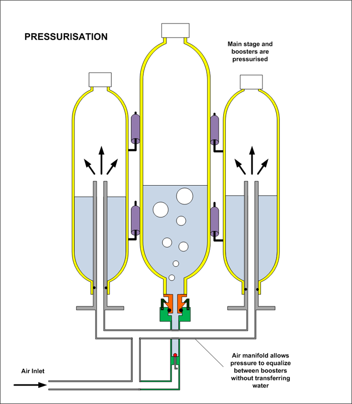
The entire rocket is then pressurised.
The open channel through the air manifold allows the
pressure to equalize between all the boosters.
When pressurised the boosters are
already trying to pull the main stage upwards. But with
the pins hooked into the tubes on the main stage the
boosters are held down.
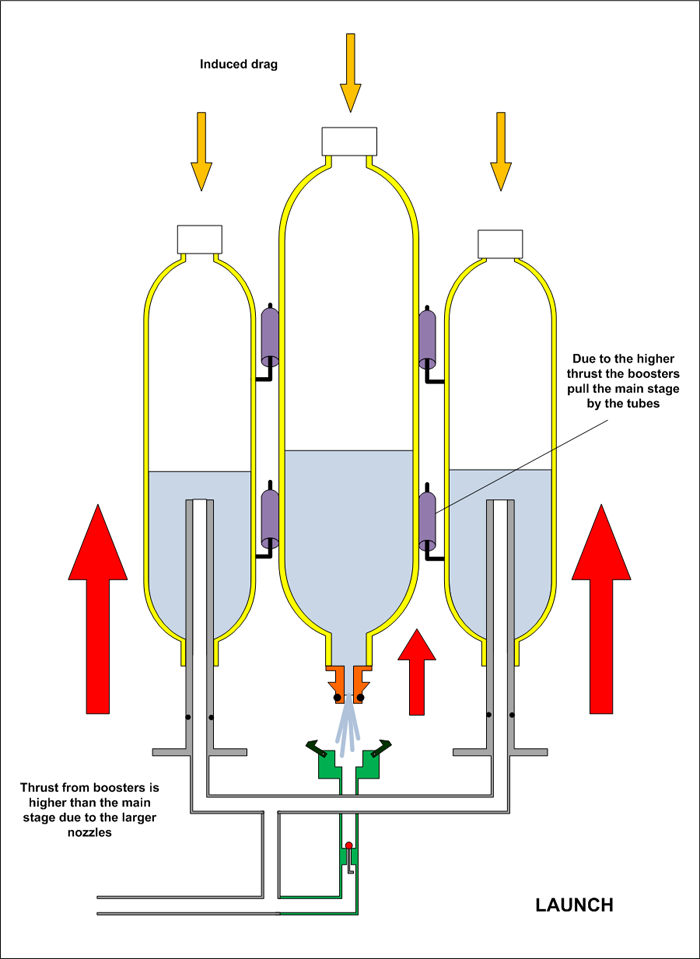
Launch is
achieved by releasing the main stage nozzle from the
launcher. This has the
benefit of simultaneously launching everything together.
The boosters having larger thrust than the main stage
will always try to "pull" the main stage with it keeping
the pins inside the tubes.
The top tubes on the main stage are there to keep the
boosters pointing in line with the rocket.
As soon as the rocket starts moving air drag starts
acting on the top of the rocket.
The air fill tubes also act as regular launch tubes
in this case giving the boosters a boost.
The booster
thrust is greater than the main stage thrust and hence
the boosters are prevented from falling out backwards.
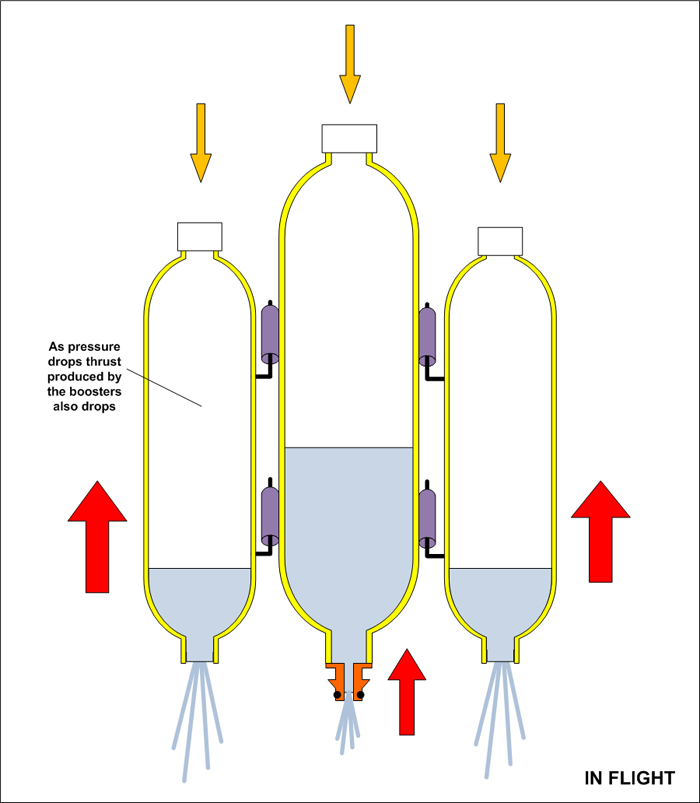
In flight, the booster pressure and
thrust start to
drop more rapidly than the main stage.
The rocket continues to accelerate the induced drag also
increases.
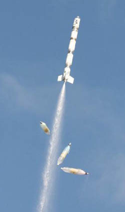
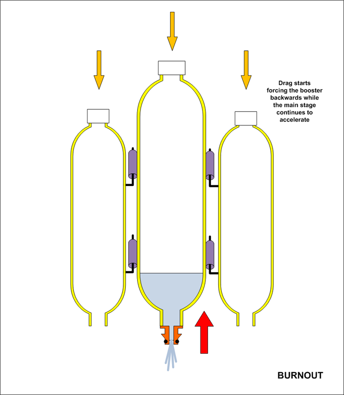
At burnout the boosters stop producing
thrust, and now the net force acting on the boosters is
just drag and gravity.
The main stage continues to
accelerate.
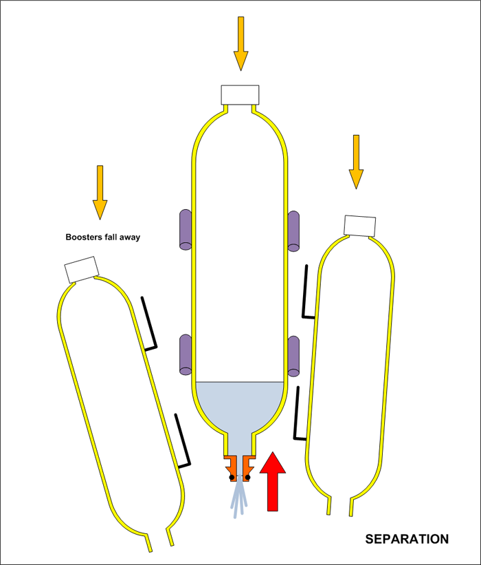
The air pressure from the drag simply
forces the boosters backwards out of the tubes and they
fall away.
The main stage continues to accelerate
upwards as long as it is producing greater thrust than
the drag.
Notes
The rocket should be designed so that the thrust phase
is much longer for the main stage compared to the boosters.
This can be achieved by having the main stage contain more
volume and/or having a smaller nozzle. Adding foam to the main
stage also prolongs the thrust.
The tubes and pins should not be too short as there will
be some amount of vertical movement between the booster and
main stage. If they are too short the boosters may separate
early due to vibration or buffeting.
The pins, tubes and main stage nozzle need to be made from
very strong materials as a lot of force is transferred
through these.
Consider using 2 or more pins on the bottom next to each
other to help spread the load.
We use smaller nozzles rather than the full bore
nozzles on the boosters as it helps to keep the acceleration
down reducing the stress on the tubes and pins.
As the rocket is pressurised there will be a small amount
of vertical movement of the boosters
as things flex under pressure. This needs to be
considered in the design so the o-rings continue to provide a good seal.
Another consideration needs to be given to the increase
in diameter of the main stage and boosters as they are
pressurised. If the booster bottle is hard up against the
main stage bottle then they will tend to want to push apart.
If a certain amount of give is not incorporated into
the launcher nozzle seats, the nozzles may wedge.
Videos
Details of the actual launcher:
Flights of the rocket with boosters:
References
A similar drop away booster concept has been used before on
experimental pyro rockets. The implementation on water rocket
shown here was inspired by Trevor's flight of his Green Ant
Shuttle: