There are different ways to eject parachutes from water rockets. The technique we like to use is called Side Deployment
(aka Horizontal Deployment) where the parachute is deployed in a
perpendicular direction to the rocket body axis.
The other common technique is to separate the nosecone and have
the parachute come out in-line with the rocket axis. This is how
most amateur pyro rockets do it.
We use the side deployment technique because we often have a
camera and altimeter mounted in the nosecone. Having
them rigidly attached to the rocket body
gives them a more stable platform on the way down.
There are a lot of different ways to achieve side deployment
as well. We like to construct ours so that the outer aero-shell is separate from the actual mechanism itself. This makes
construction and adjustment much easier. It also allows the
mechanism to be easily reused if the aero-shell becomes damaged.
The procedure below outlines the general steps of how we
construct ours. A lot of the basic concepts have been adapted
from other people's designs (See
References). No specific dimensions are given here as these will
depend on the bottles you use and how much space you want to
allocate for the parachute.
 |
1. |
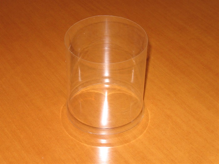
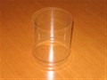
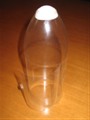
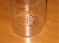
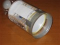
Get a clean bottle with a nice aerodynamic shape
and straight sides.
Remove the label and clean off the glue with mineral
turpentine. |
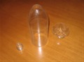 |
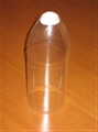
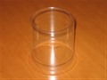
2. |
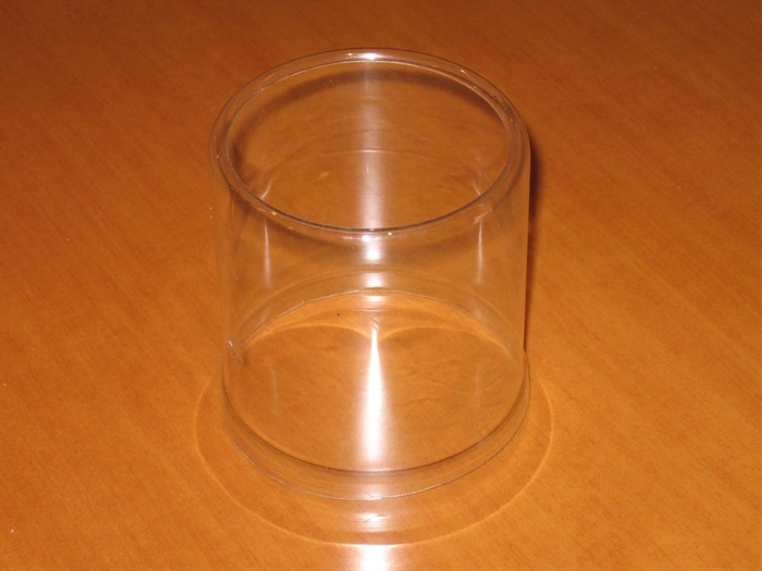
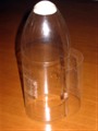
Cut off the neck and the base off the bottle. |
 |
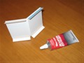
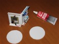
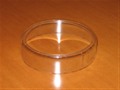
3. |
Glue half a ping pong ball into the hole left by the
neck of the bottle. This gives the nosecone a nice rounded
shape. If you are using different sized bottles look through
the kids toy box because there are bound to be plastic
balls of varying diameters. Don't let the kids see you
though. |
 |
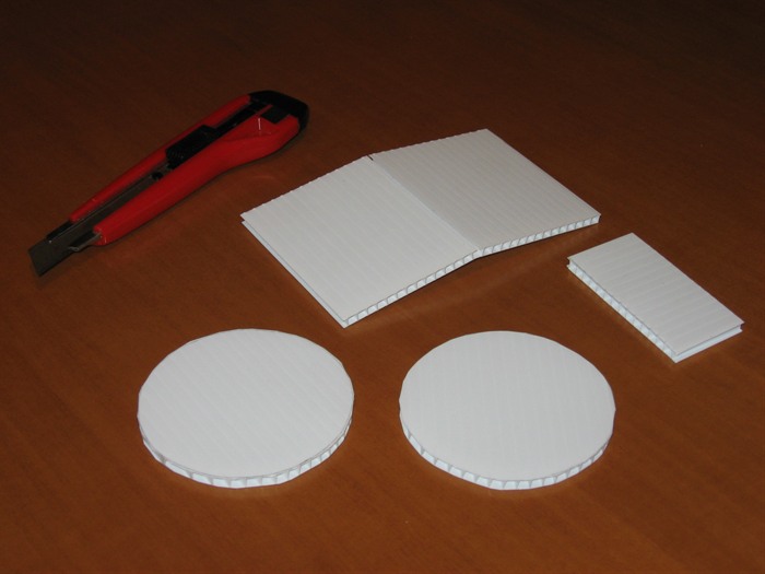
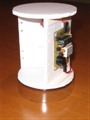
4. |
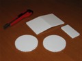
Cut two circles out of some Corriflute
sheet. You
can find this stuff almost everywhere. Old signs make a good
source.
WARNING: In the interest of public courtesy when obtaining these signs, make sure you don't get
the ones with "Wet Paint" written on them. |
| |
|
Make sure the circles are a somewhat loose fit in the bottle. This
will allow the mechanism to be removed from the bottle for
servicing. |
| |
|
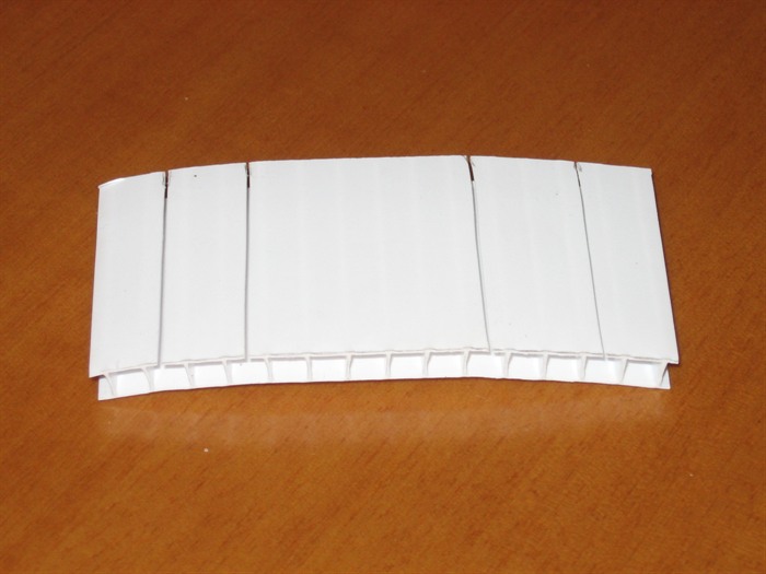
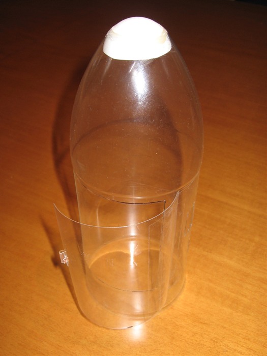
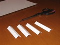
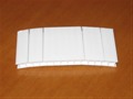
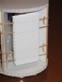
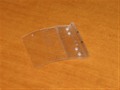
Cut out a larger rectangular section from the Corriflute
sheet. The size of this will vary depending on your
bottle size and the height you want to make it. Make it
taller to fit bigger parachutes. The corrugations should be
oriented vertically. Now slice only one side of
the rectangle half way along. (see photograph at left) |
| |
|
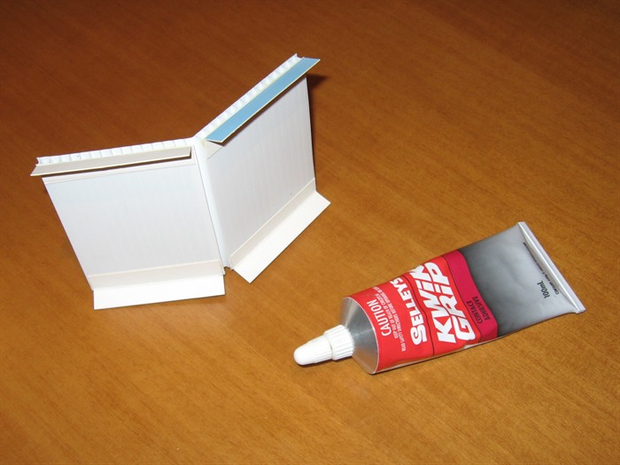
Bend the rectangle to make a 'V'. |
 |
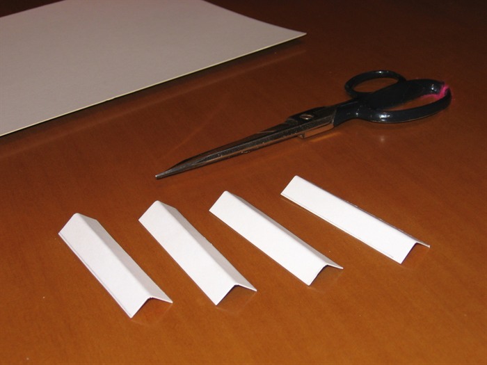
5. |
Next, cut 4 strips of cardboard and bend them 90 degrees along
their lengths to make four 'L' shaped brackets. |
 |
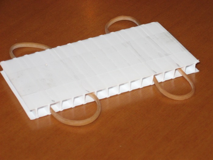
6. |
Glue these to the edges of the V with contact glue as
shown in the photograph. |
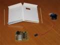 |
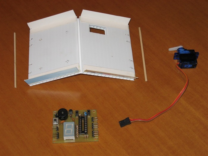
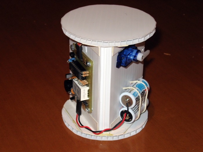
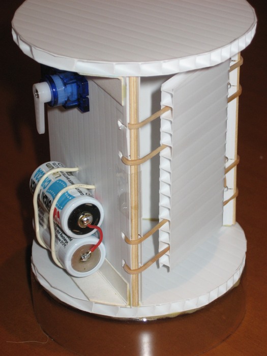
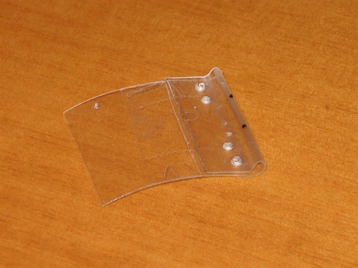
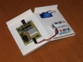
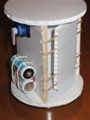
7. |
Now, make all the necessary holes in the
V to support
your release mechanism. You can use a Tomy timer, or as we
are using here an RC servo motor connected to one of our
flight computers.
Make holes and slots along the vertical edges of the V.
These will hold the rubber bands that eject the parachute.
|
 |
8. |
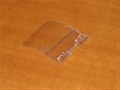
Cut out another smaller rectangle (the
ejection plate) from the Corriflute
sheet. This will be used to eject the parachute. Make
sure the corrugations run horizontally. Cut on one side only
of the ejection plate to make 4 cuts along the
corrugations. |
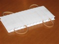 |
9. |
This
lets you to place
the rubber bands inside the corrugations. Use a piece of
tape to close the cuts again.
NOTE: When attaching the rubber bands to the V make sure
that the cuts in this small rectangle are facing away from
the parachute. This ensures that the rubber bands can't come
out through the slots. |
 |
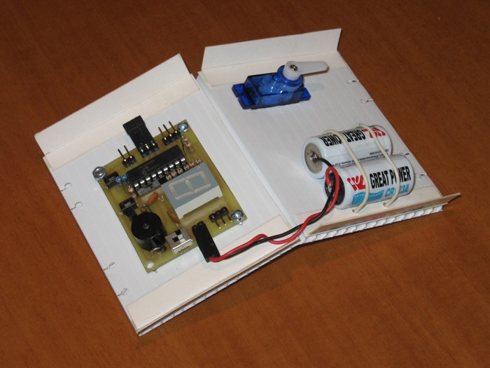
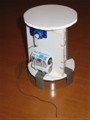
10. |
Securely attach all your release mechanism components to
the V. |
 |
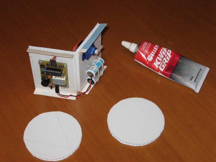
11. |
Glue the V to the two previously cut
out circles. |
 |
12. |
You want to make sure that no pieces
are overhanging the circles because you will need to be
able to slide the entire assembly into the nosecone
aero-shell.
This allows you to remove the entire mechanism for
servicing. |
 |
13. |
Keep the inside of the V clear of all
major protrusions. You can mount things like batteries in the
far end of the V. |
 |
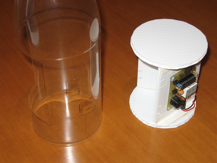
14. |
Slide the mechanism into the aero-shell. You can push it
up as far as it can go. This will stop it from moving
upwards when the rocket starts decelerating shortly after
burnout. You can mount it lower, but you need to glue some
stops to the inside of the nosecone to prevent the mechanism
from moving up. |
 |
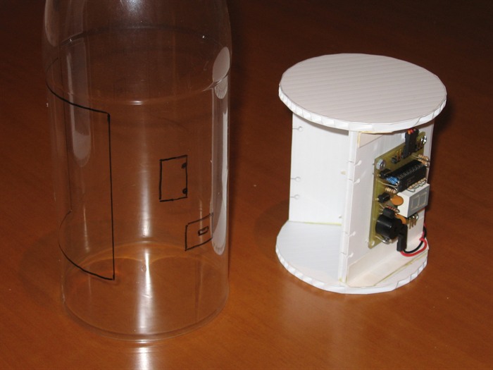
15. |
On the aero-shell, mark out the boundary of the mechanism
where the parachute will come out.
NOTE: You should make the hole only
a little smaller than the cavity. This will help
prevent the parachute from snagging on the way out.
Also mark any access holes to buttons and controls, and
don't forget the altimeter vent hole if you have one fitted. |
 |
16. |
Now cut out all the necessary
holes. We often only make small holes for the switches to
help streamline the aero-shell. To make small holes just heat
a large nail or screw on the stove top and push it through
the plastic. |
 |
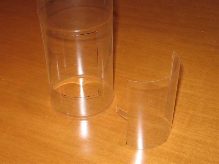
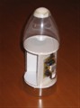
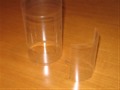
17. |
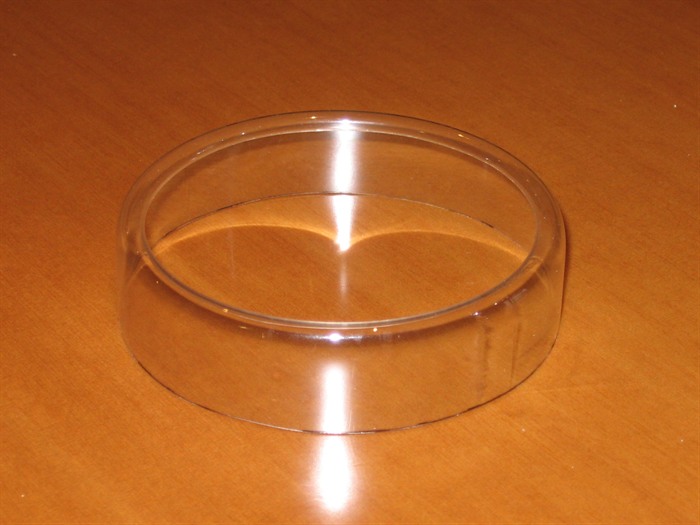
Next we make the support ring for the
mechanism. This holds the mechanism in place against
positive G's. Cut a cylindrical section from another
bottle and make sure its diameter is a little narrower
than the aero-shell bottle. |
 |
18. |
Curl one end of the section on an old
frying pan on low heat. You can use the curling
technique shown in the
Splicing
Video. |
 |
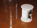
19. |
Trim the bottom of the section so there
is approximately 1 or 2 cm of straight wall left. |
 |
20. |
Glue the entire mechanism
to the top of the support ring. |
 |
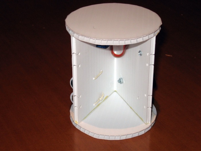
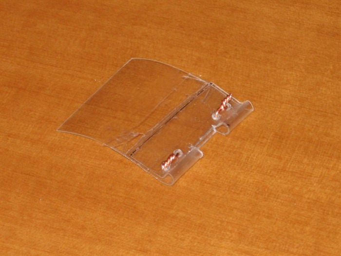
21. |
Fit the rubber bands into the holes
made earlier
along the edge of the V. We use two skewer sticks on the
edges to give the rubber bands a nice rounded edge to sit
on. The sticks are held in place with a small piece of
sticky tape. |
 |
22. |
Detail showing how the rubber band is
threaded. Experiment with the rubber band size to give
you different tension on the ejection plate. |
 |
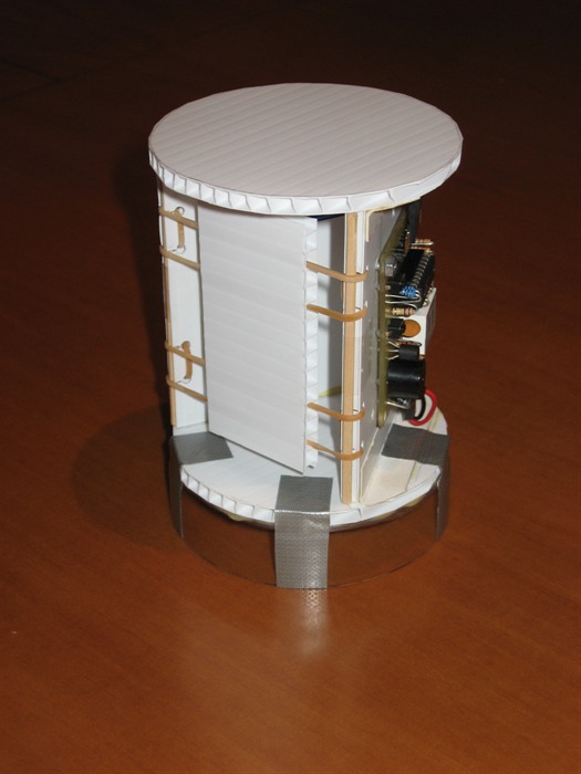
23. |
You can add extra tape to the base to
ensure a good join between the mechanism and support
ring. (Silver tape shown here) |
 |
24. |
The parachute door comes next. How this is attached and
how the door latch mechanism works will depend on your design.
The door hinge can be on the side or top or bottom. We put
ours on the side as it works better with our latch. If you have your door with the hinge on the side, you
can easily make the hinge from some packing tape. If you have your
hinge door at the top or bottom you may want to use some
other method as the hinge needs to be fairly small due to
the curvature. |
 |
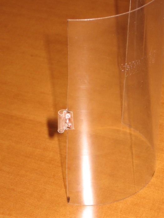
25. |
Cut out the door so that it is at least
5mm bigger than the hole all the way around. Often you
can use the same bottle that you made the support ring
out of.
Leave a small tab on door (visible in the previous
photo) and bend it back over so that it makes a loop.
Because this part of the door will have a lot of force
pulling on it, we secure the bent over tab with some
wire. You can use a heated paperclip to "drill" two
holes through the tab and then thread the wire through
it.
NOTE: A simpler alternative to the pin pulling
set up shown here is to use
a rubber band to
release the door directly. |
 |
26. |
Attach the door to the aero-shell. This
can be achieve with strong tape. You may want to use a
piece of cloth instead that is glued to the door and
shell for extra strength. In practice we find the
tape is sufficient. Two layers of clear packing tape
were used in the photo. |
 |
27. |
Now its time to make the other side of
the latch that holds the door. This is made from a strip
of left over PET bottle used to make the door and
support ring. Again we secure the bent plastic with wire
the same way as was done on the door. Here you can see
the 4 holes made by a hot paperclip wire. |
 |
28. |
After securing the plastic loops with
wire, cut out the slot for the door latch with a craft
knife. Make sure the door loop is a couple of mm
smaller to make sure the latching mechanism comes apart
cleanly. |
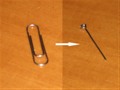 |
29. |
Using some long nose pliers turn a
paperclip into the latch pin as shown. Make sure the end
of the pin is sanded or filed to a nice smooth finish to
stop if from getting caught in the latch mechanism. |
 |
30. |
Insert the latch pin through the latch
and door, and tape the latch to the aero-shell. This
makes sure that the latch and door are well aligned.
NOTE: Don't make it too tight. The door should sit
snugly against the aero-shell, but the pin should be
free to move. |
 |
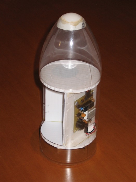
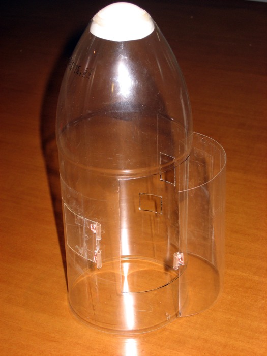
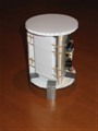
31. |
The aero-shell is now almost complete. |
 |
32. |
Attach a length of string to the servo motor arm. (horn).
Use a fairly strong thread or nylon line. |
 |
33. |
Insert the mechanism into the nosecone
and thread the string through the appropriate hole above
the latch. Insert the pin in the latch and attach the
string to the pin so that the string is fairly tight. |
 |
34. |
Okay time to go get some coffee here
comes the tricky bit. Now test the mechanism to see if it unlatches the
door. You can cut the pin to length or adjust the string
until all works properly. Secure the string knot with
some glue to stop it from coming loose. |
 |
35. |
To secure the mechanism inside the
aero-shell just tape the support ring to the inside wall
of the aero-shell. You could secure it in other ways if
you are expecting high G forces. You can use nylon
screws through the support ring and the
aero-shell. |
 |
36. |
The side deployment nosecone is now
complete. You just need to attach the parachute to the
rocket. Tying the parachute string somewhere near the
center of gravity will ensure that the rocket falls
mostly sideways helping to increase the amount of drag
on the way down. |
 |
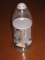
37. |
All that remains is packing the
parachute and the nosecone is ready for flight. We
normally tape the nosecone to a pressure tested bottle
and keep the entire nosecone ready for when needed. The
whole thing then just screws into either a Robinson or
tornado coupling.
Make sure you test the deployment mechanism a few times
before flight. |
There are many examples of horizontal deployment mechanisms.
Here are just a few: