 |
1. |
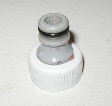
This stager is designed to work with a
standard 9mm Gardena nozzle. If you don't have one
already, you will need to make the nozzle first. Here's
how: Making a Gardena
nozzle. |
 |
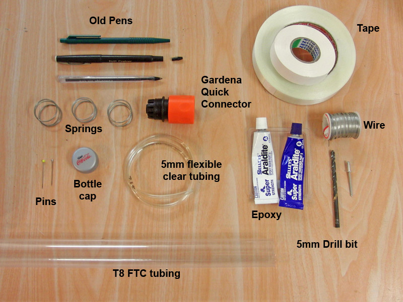
2. |
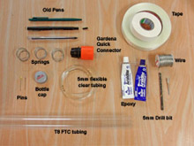
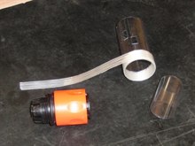
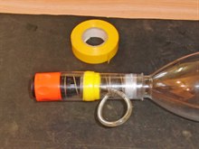
Here are the materials you will
need. Make sure that the Gardena quick connector you
are using will not slide into the FTC. There is a flange
on the quick connector just behind the thread. The
flange diameter should be bigger than the FTC diameter.
Some cheaper brand quick connectors are slightly
narrower and could potentially slip inside the FTC. |
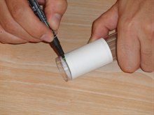 |
3. |
Cut two lengths of the T8 FTC. One
should be ~70mm long and the other ~35mm.
When you cut these
out, you need to make sure that the edges are as square
as possible. Use a piece of paper wrapped around the outside
and mark along the edge. Carefully cut along the lines.
If the edges are not square then the sustainer will not
sit straight on the booster. You can use scissors to cut
the FTC along the line. |
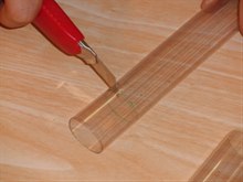 |
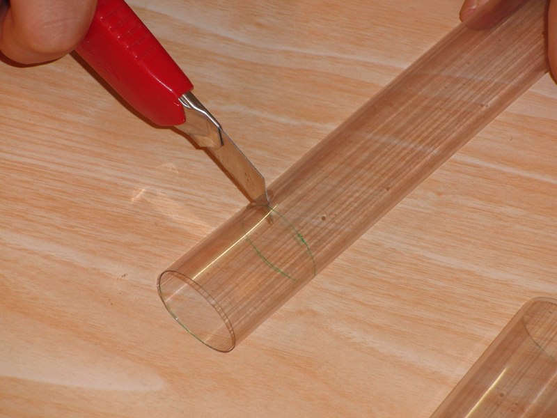
4. |
Roughly cut the FTC piece off with a
craft knife, and then trim to the marked line with
scissors. |
 |
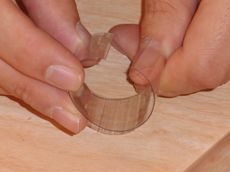
5. |
Cut the smaller FTC tube lengthways with a
pair of scissors. |
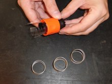 |
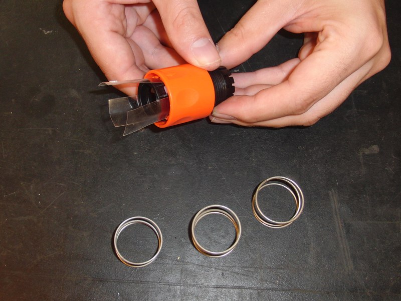
6. |
Remove the orange collar from a Gardena quick
connector by inserting 3 strips of PET plastic
underneath the collar's locking tabs, and then pulling
back on the collar.
Remove the spring and re-assemble the collar making
sure you have the white locking tabs in place. You will need 4
of these springs altogether so you can remove these from
old quick connectors. Make sure the springs are
identical in size.
At this point test to see if the sustainer nozzle
locks all the way into the quick connector. If it doesn't, you can modify the
quick connector as shown here:
Launcher Fix |
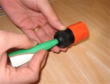 |
7. |
Sand the internal hole of the Gardena
quick connector to allow the epoxy to grip better. |
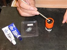 |
8. |
Put a piece of Blu-Tack, plasticine or
modelling clay on the workbench and stand the
Gardena connector on it's end (orange collar pointing up) so
that the Blu-Tack blocks the central hole. Mix up some epoxy and carefully pour it through the open
end. Pour enough epoxy
in so that it is about 5-10mm deep. It's better to use the
stronger epoxy rather than the 5 minute stuff.
Let the glue fully cure for 24 hours. |
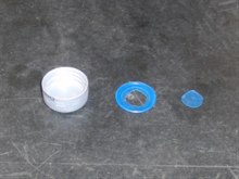 |
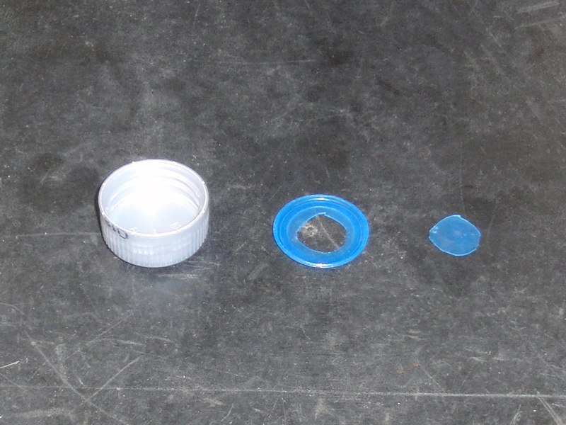
9. |
If the cap is the kind with a removable
seal then remove it from the bottle cap and cut a hole
in it as shown. The bottle cap may not have a
removable seal or may be one of the
type C caps then you don't need to do this step. |
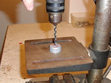 |
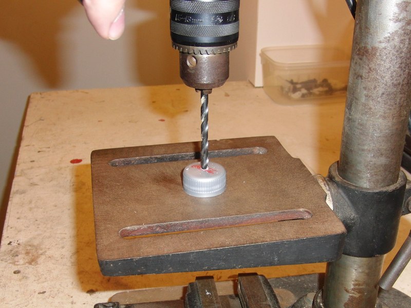
10. |
Assuming the outside diameter of your
tubing is exactly 5mm, drill a 5mm hole
straight through the top of the cap. It does not need to be
exactly on center.
NOTE: The tube needs to be a snug fit in this hole.
You should not be able to slide the cap freely on the
tube. If the hole is too big, get a new cap and drill a
smaller hole. |
 |
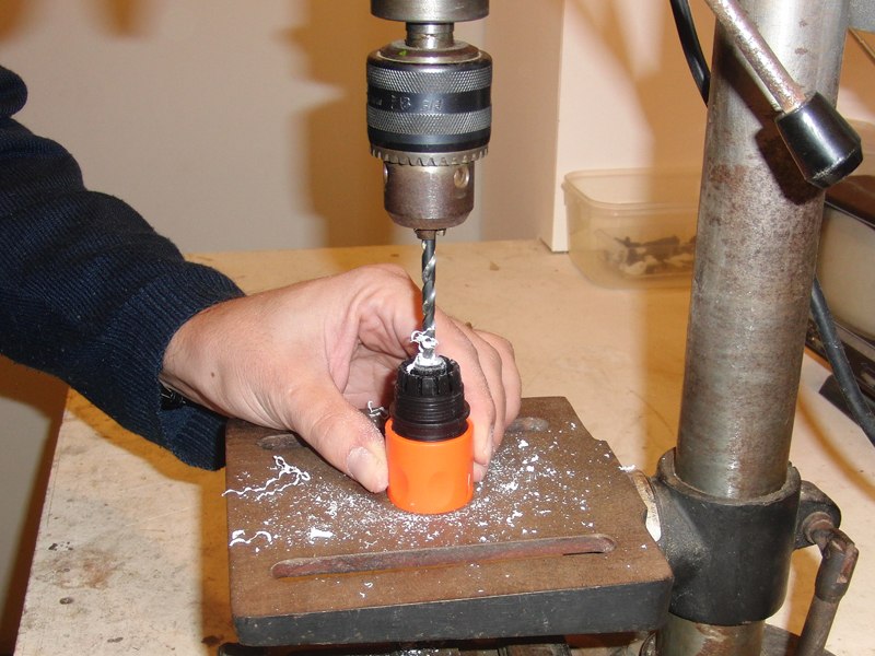
11. |
Now use the same drill bit and drill a hole in
the epoxy glue of the Gardena quick connector. |
 |
12. |
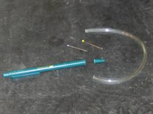
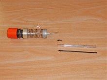
Cut about a 220-230mm length of the
clear tubing with a pair of scissors. Find an old
plastic ball point pen that has a conical pen tip. You
may need to look through a number of them, as some have
small ridges on the inside. You may also find other
small plastic cones as part of other components. As long
as it is small enough to fit in the end of the tubing
then it should be good. The conical section needs to
have smooth internal walls to allow the valve to seal
properly. |

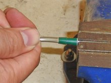 |
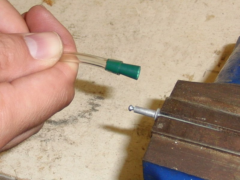
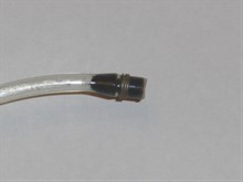
13. |
Push the cone section into the tubing
as far as it will go. This is easy to do if you grip the
end of a pop rivet or something similar in a vice and
then push the pen tip over it.
NOTE: It is important to have the pen tip securely
pushed into the tubing. If it is loose, it may get
pushed out under pressure. |
 |
14. |
Cut the head off a pin with a plastic
round head, or alternatively find a ball bearing of the
right size and make sure it fits inside the pen tip cone
section. It should be big enough not to fall through
the smaller hole of the cone.
Heat another pin and push it through the plastic
walls of the cone so that the round pin head can move up
and down, but cannot fall out. |
 |
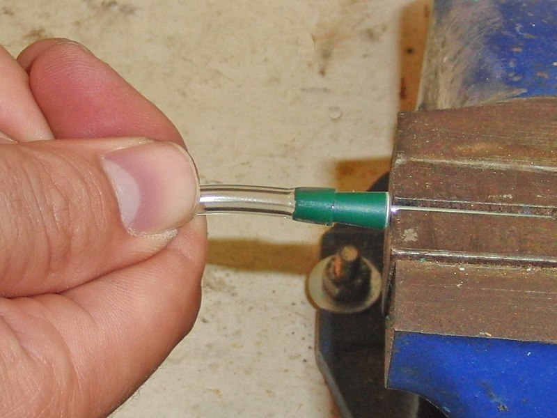
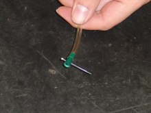
15. |
Push the pin through, cut it with a
pair of wire cutters a couple of mm from the pen tip,
and bend it with pliers to stop it from falling out. |
 |
16. |
You can wrap a couple of wire loops
over the tubing and tighten with pliers. |
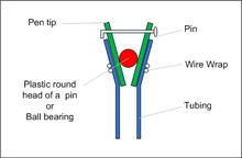 |
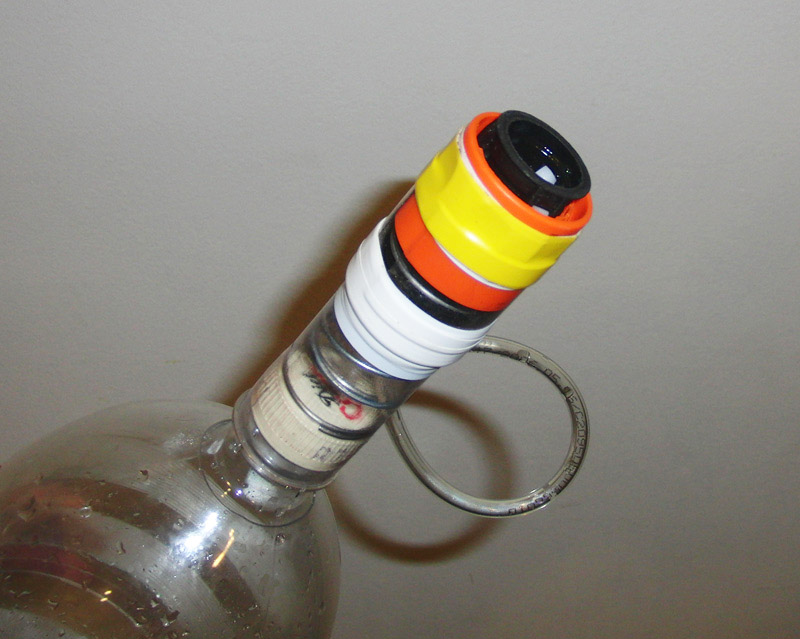
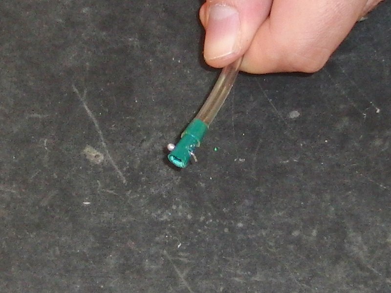
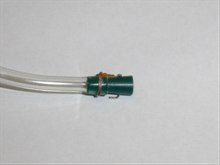
17. |
This is how the non-return valve should
look. |
 |
18. |
Wrap a length of tape around one end of
the longer section of FTC. Here we are using glass
strapping tape about 10mm wide. Wrap enough of the tape
until the outside diameter of the tape is the same as
the orange collar diameter. |
 |
19. |
Cut out two slots as shown in the
FTC body. These should be wide enough to let the tubing
move freely inside them. Cut them
elongated so the tubing has room to move as the spring
compresses.
NOTE: The location of these slots will depend on how
your springs sit. I assemble the stager first without
the tubing and then draw on the outside of the FTC where
the holes need to go. The upper hole should be as high
as possible and the lower hole should be as low as
possible. This allows the tubing to sit more vertically
in the cap and the quick connector giving a better seal. |
 |
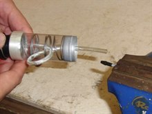
20. |
Insert the free end of the tubing
through the quick connector and pull it all the way
through until the non-return valve is sitting snugly
inside the quick connector against the epoxy.
Thread 3 of the springs completely onto the tubing,
with the first spring pushed all the way up to the
flange of the quick connector and the fourth spring should be only partially threaded.
Let the tubing emerge out the side of the 4th spring.
Now insert the springs and tubing into the FTC body,
allowing the tubing to emerge from the bottom hole. This
is a little fiddly but not difficult. After all the
springs are inserted, make a loop in the tubing and
rethread it back through the upper hole and back down the center of the FTC body.
Pull the tubing out as far as it will go (the loop
will tighten) and insert the tubing in the top of the
bottle cap.
You can now push the cap into the FTC body. The caps and
FTC we use fit snugly together. Your FTC may be a little
bigger or cap smaller, so at this point you can wrap a
bit of tape around the cap to give a tight fit. You may
need to try a few caps otherwise, until you find one
that works well. |
 |
21. |
For the next step we need to widen the
free end of the tubing so it cannot come out of the cap.
For that we use the plastic tip from another pen. This is a very
common type of pen, with a metal tip fitted in a plastic
adaptor with the ink straw inserted from the other end.
Pull out the metal tip with pliers, and remove the ink
straw. You'll be left with the hollow plastic adaptor.
This is a nice size for the tubing, and the tapered
and makes it easy to insert into the tubing.
Alternatively you can use something like a round glass
bead with a hole in it and push it into the end of the
tubing. |
 |
22. |
You can again use the pop rivet or
similar in a vice to hold the pen tip. |
 |
23. |
Push the tubing over the pen tip until
the end of the tubing is level with the end of the pen
tip. |
 |
24. |
Now wrap a couple of loops of wire over
the end to prevent the pen tip from being pushed out
under pressure. |
 |
25. |
Push the tubing back through the cap
until the pen tip is pushed up snugly against the hole
in the cap. The tubing loop will loosen again.
Screw the cap onto the booster bottle and tighten.
Now push the FTC body down over the cap until it rests
on the bottle flange. This will help support the sustainer
during acceleration.
NOTE: There needs to be quite a bit of friction
between the cap and the FTC body so that the spring does
not push the cap out. |
 |
26. |
Take the smaller piece of split FTC and
slip it over the rolled up tape at the top end of the
FTC body. Tape this down with the
electrical tape. Make sure you tighten the tape really
well and wrap it several times. You also need to pay
special attention to the alignment of the split FTC so
that it is not at an angle to the FTC body. |
 |
27. |
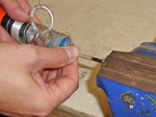
NOTE: The next step is very
important, and it helps to get someone to help you.
Place the nozzle into the stager and push down the
inner part of the quick connector compressing the spring
until the flange rests on top of the FTC body.
While holding down the inner part of the quick
connector, slide the orange collar all the way up until
the nozzle is locked. Now wrap electrical tape around
the orange collar where it overlaps the short
piece of FTC. What you are trying to achieve is to
attach
the orange collar to the split FTC.
Once you tape it down firmly, (use a few wraps) you
can release the nozzle, and the inner part of the quick
connector should spring out again.
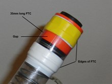
There will be approximately a 10mm gap in the split
FTC. This gap cap be used to place a locking tab in
the stager. (see below) (This image was taken from our other stager and
is why the lower tape is white in this image) |
Because of YouTube's 10 minute limit, we have broken the
construction tutorial into two parts.
Because there are so many varieties of springs and quick
connectors it is difficult to predict how much force your
springs will give.
You should get a reading of 800grams or more. If it is much
less than that, you may find that the stager fails to open in
flight. (We found out the hard way). This means your sustainer
needs to weight at least 800 grams to keep the stager locked.
This is not unreasonable for a small sustainer considering it
may weigh 200 grams with 600mL of water. If the fully fuelled
sustainer weighs less than than, you can still use this stager
with a locking tab. (See below)
You may find that you need to adjust the spring tension of
the stager. This can be achieved by trimming the bottom of the
FTC body and pushing it down against the bottle flange again.
This will increase the spring tension. Trim a couple of mm
at a time.
To use the stager, simply fill the booster with water and
place it on the launch pad. Fill the sustainer with water and
push the sustainer nozzle into the stager and let the
sustainer's weight lock the stager.
The stager does not need to be mounted on top of the booster.
You can run the length of tubing to another part of the rocket
to supply air to the sustainer.