The log is in chronological
order so to see the most recent post you
need to Jump To The Bottom.
You may need to refresh this page to see any
latest updates.
CAUTION: If you are going to
attempt to build rockets such as these,
please exercise extreme care when testing
and flying them. This rocket uses very high
pressures that can potentially cause severe
injury to yourself and those around you.
Always double check your equipment and
review safety procedures before every test
and flight. See more information on
Safety Guidelines.
Build Log
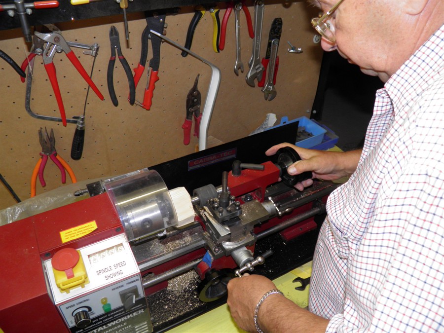
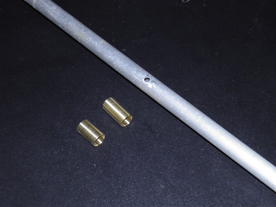
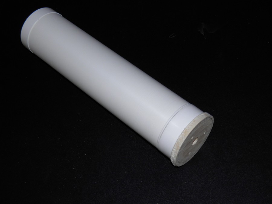
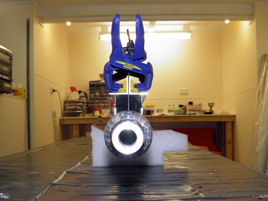
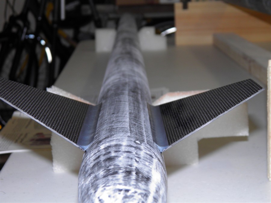
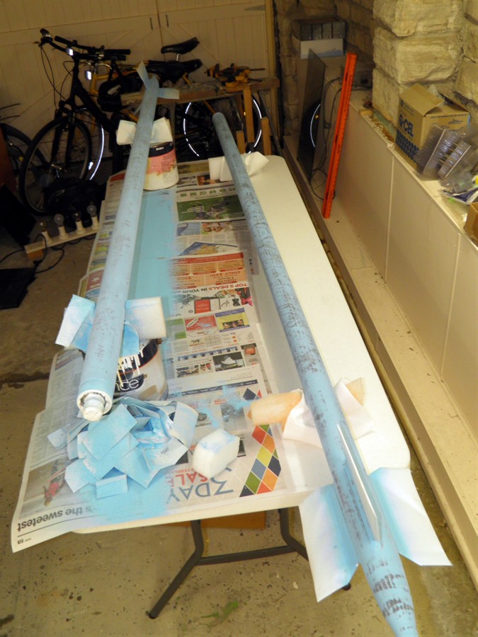
1 January 2015 - Machined up
launch tube inserts to plug holes in the launch
tube. this is because it was the only 15mm
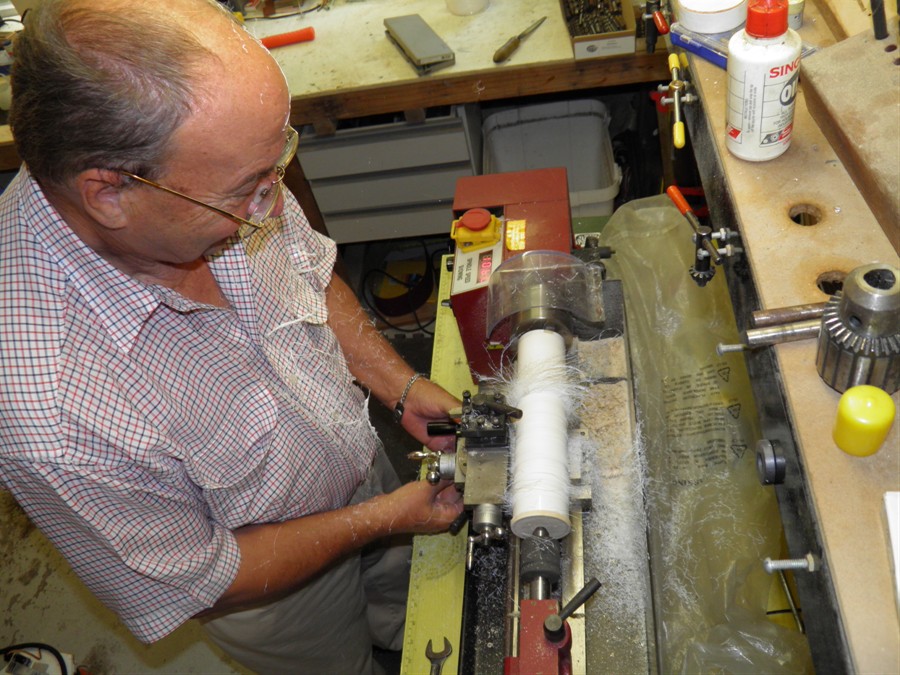
launch tube we could find. We glued these in place. Machined up
wooden end plug for machining down PVC pipe
to make coupler mandrel. Made coupler
mandrel. Mandrel OD is 59.15mm
Made a 5 wrap coupler out of 200gsm glass
(glass was 100cm long) this will be used for
nosecones.
Made 4 wrap 84gsm coupler. One layer of
baking paper. (1 pump and brush) This
coupler will be used to join the long tubes.
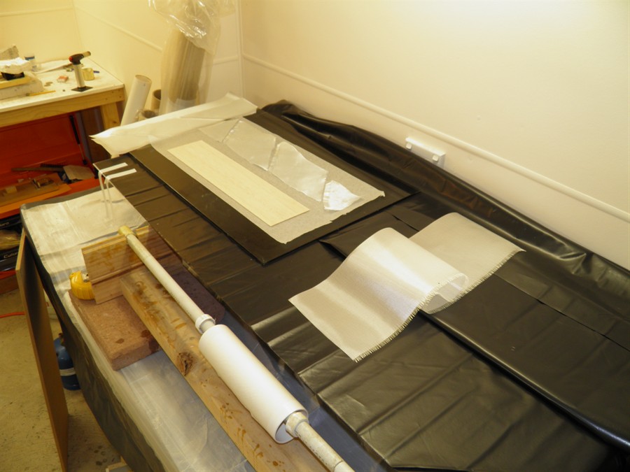
Laminated one side of balsa sandwich
200gsm lower layer bias cut, with 1 layer of
84gsm normal cut. Used left over glue from 4
wrap coupler.
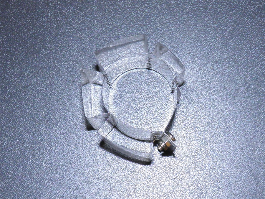
Made 6x 8.2mm wide PVC rings to be used
in deployment mechanisms to tap holes into.
Machining end plugs for mandrel
Launch tube hole covers
Making coupler and
balsa sandwich
Machining mandrel
That's one way to grow hair
PVC rings
Rolling new nosecone coupler
Mandrel and wooden end plugs
End plugs in mandrel
Curing
Cured coupler on mandrel
2 January 2015
- Made a 5 wrap coupler out
of 84gsm cloth. 160 x 980mm - Used 1 pump
for this and with the left over epoxy we
made the second half of the balsa sandwich.
We trimmed and sanded the coupler made
yesterday.
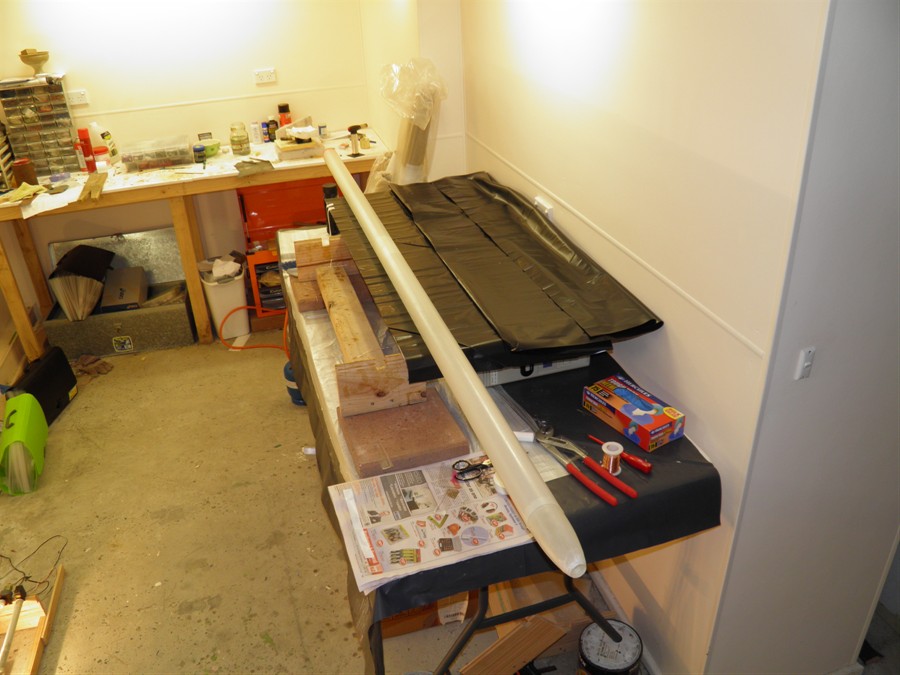
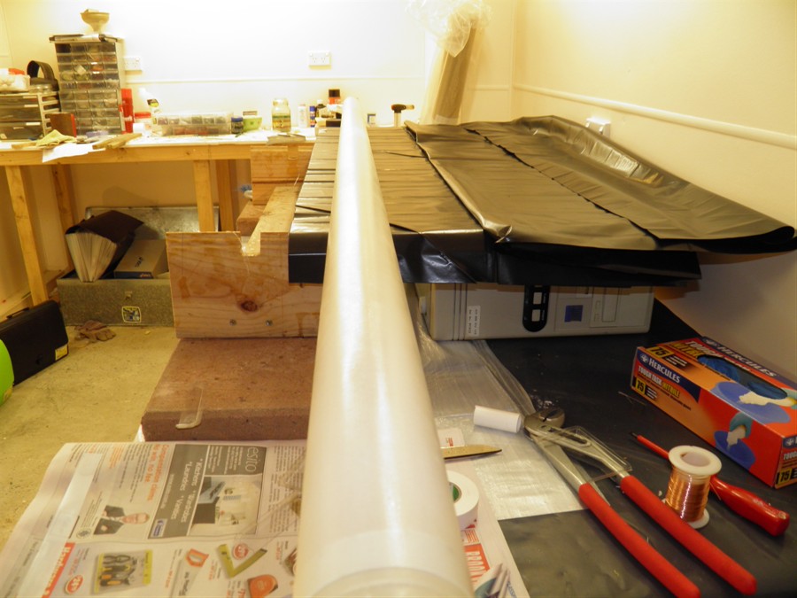
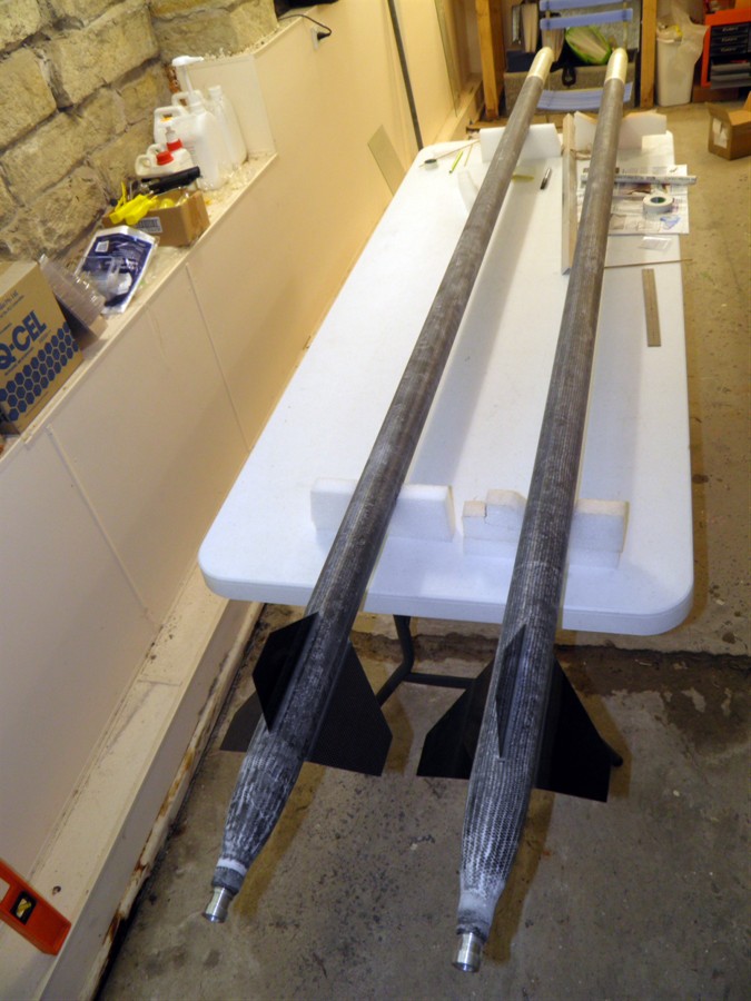
3 January 2015 - Trimmed long tubes and 5
wrap coupler. Coupler fits well into long
tubes. Made a second coupler with 5 wraps
and also made the electronics mounting tube.
We spent a considerable amount of time
thinking how to attach everything inside the
payload section against the G loads. We are
going to try going with a central fiberglass
tube to attach everything to rather than
bulkheads made with the balsa sandwiches. We
found a paper roll that was the right
diameter and so we made a 5 wrap 200gsm
cloth wrap.
Rolling coupler and electronics
tube
Curing on the rotiserrie
Payload and nosecone bulkheads
Electronics
Tube test assembly
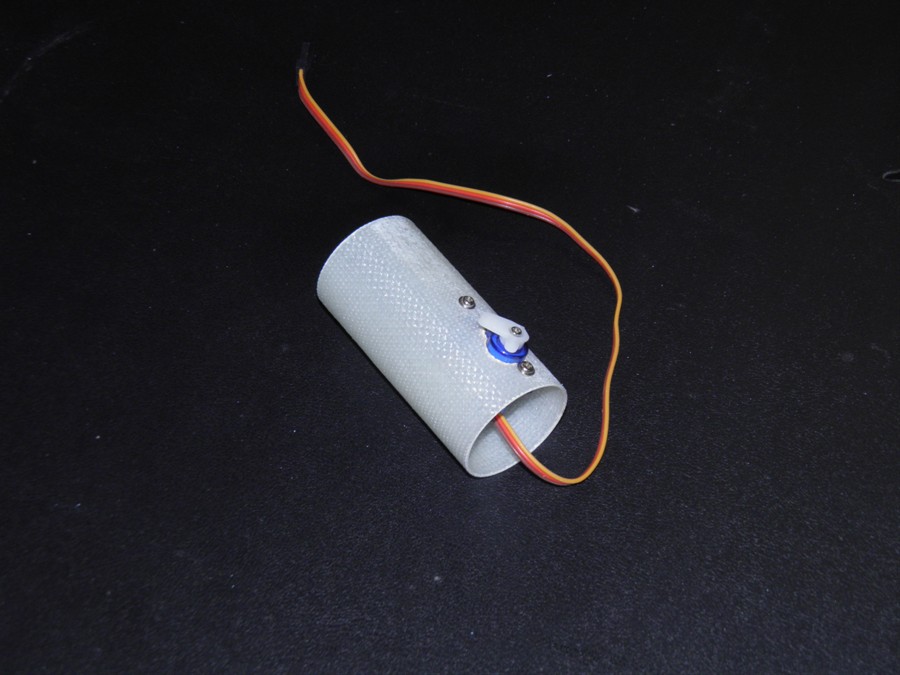
4 January 2015
- We trimmed the second
coupler and also the electronics tube. We
mounted the servo motor inside this and
looks solid enough to hold against the g
forces. We are going to try to mount the
electronics a little differently this time.
We are going to use velcro on the inner tube
and on the back of all the devices to hold
them in place. This also allows us to remove
them and use them on other projects or
replace failed ones easily. The devices will
also sit against the bottom bulkhead to
withstand the +ve g forces. Having all the
electronics mounted around the tube facing
outward, gives us easy access to all the
buttons and displays.
We will most likely use a screw switch as
we did on the Shadow to make sure the power
can't get interrupted during high
acceleration.
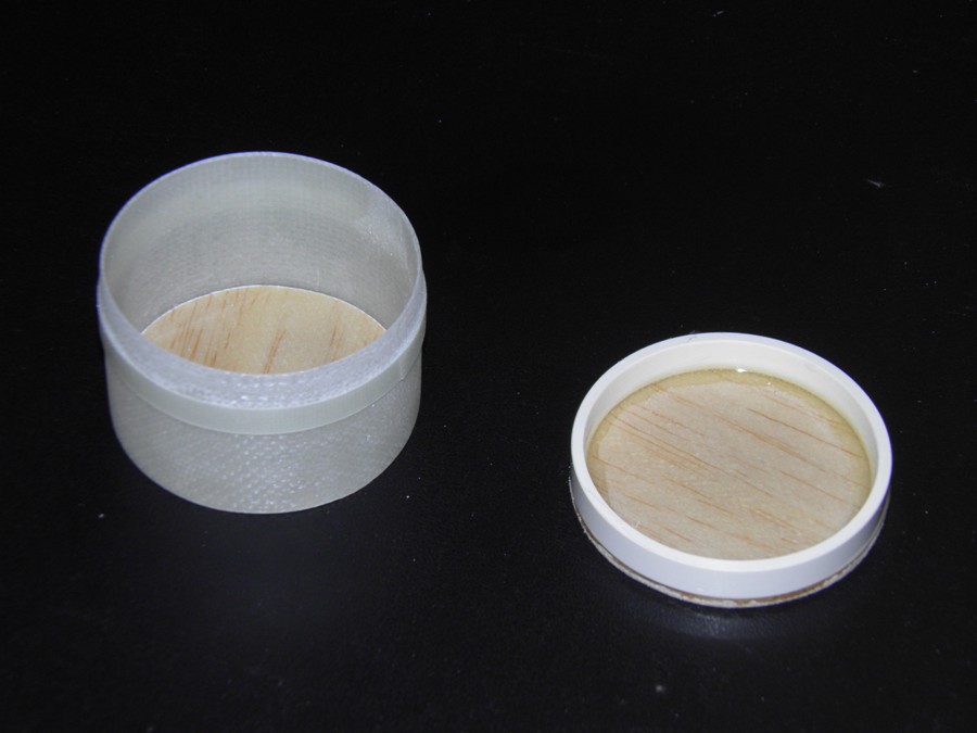
We also glued the PVC ring to one of the
bulkheads and made the thrust ring for the
nosecone coupler. The nosecone coupler was
cut to the right size as well.
Electronics tube with servo
motor
Nosecone coupler and
top payload bulkhead
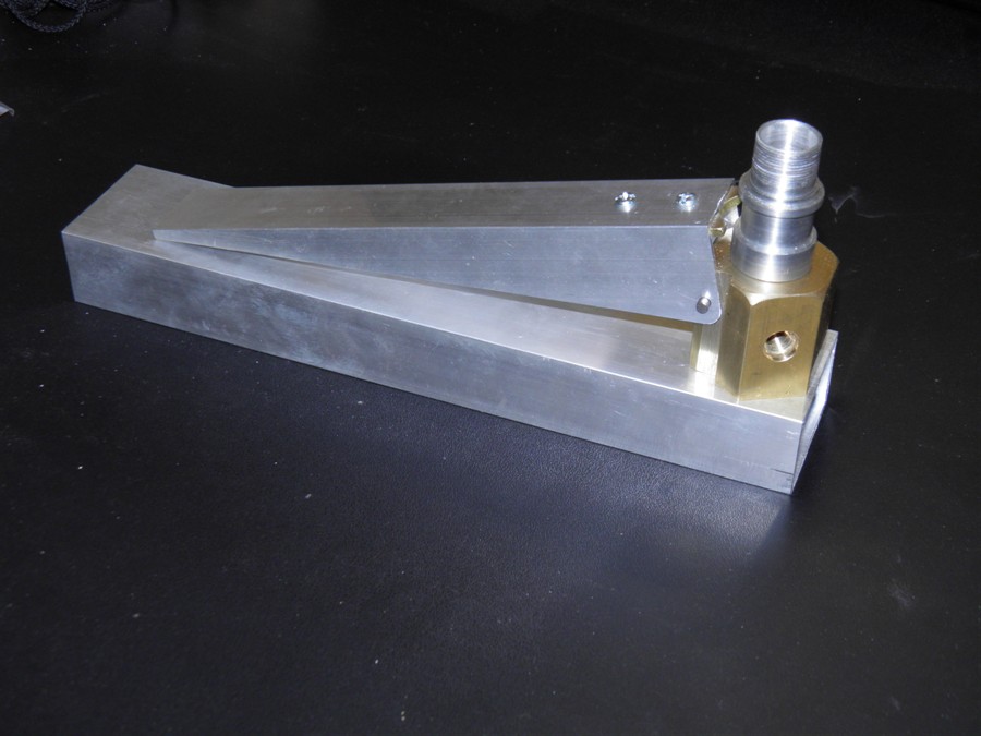
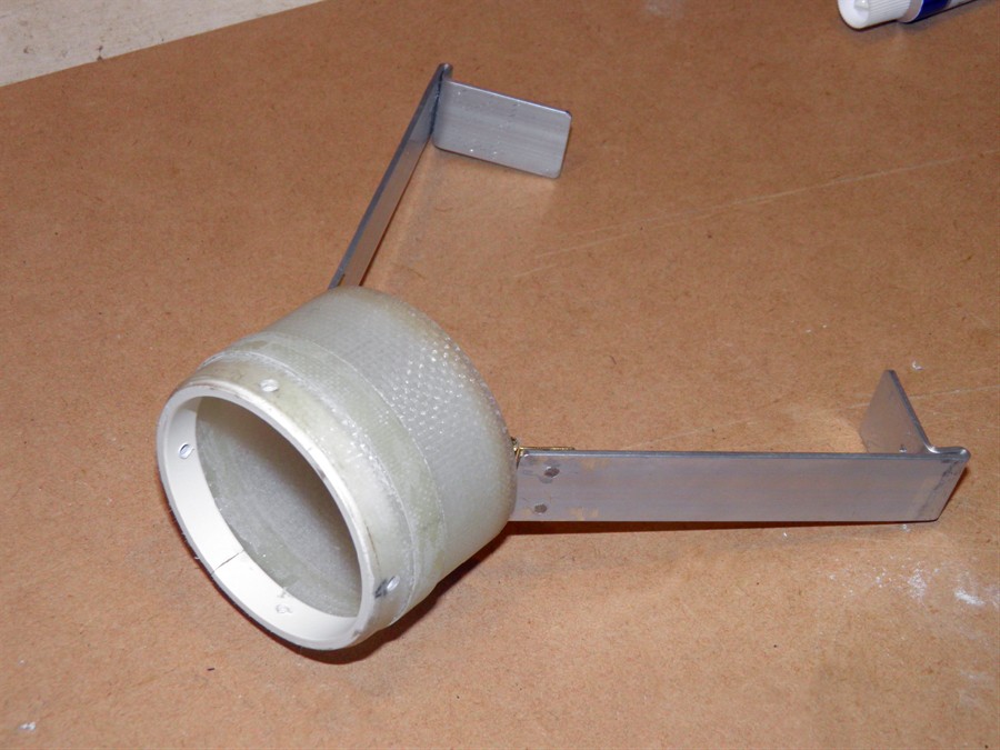
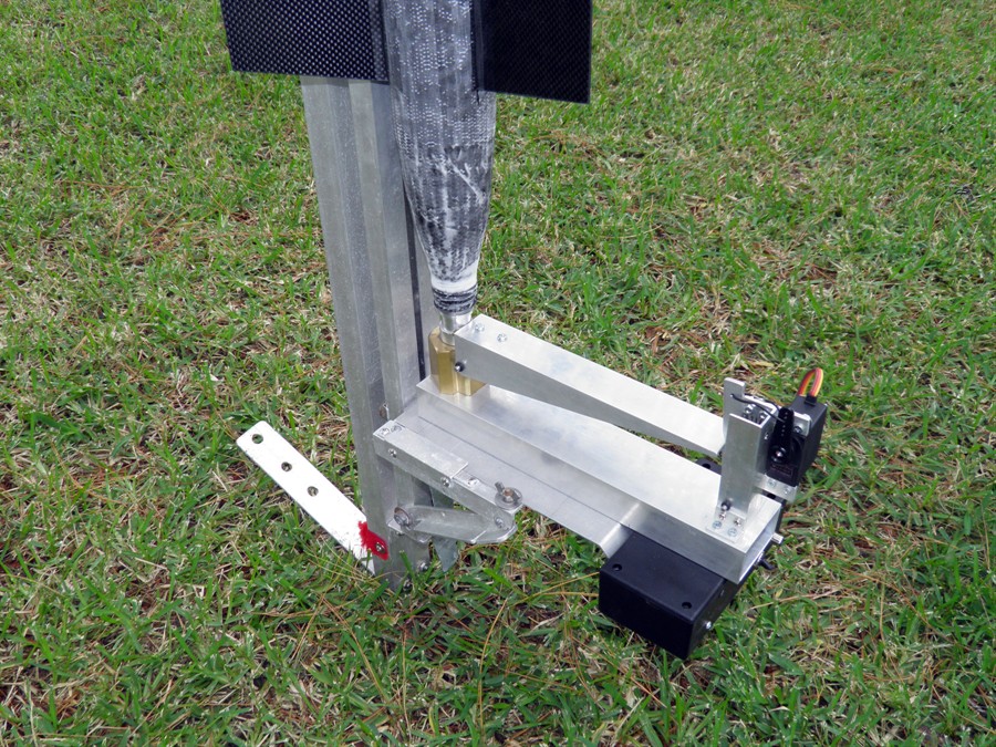
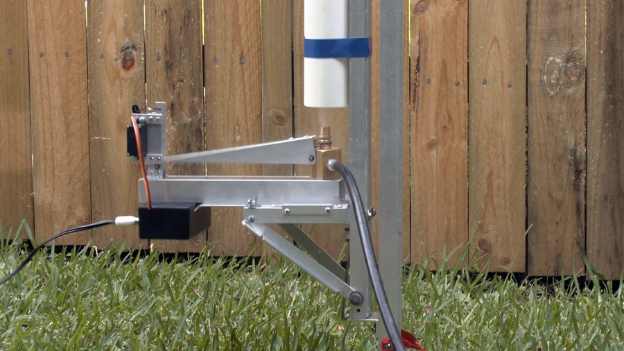
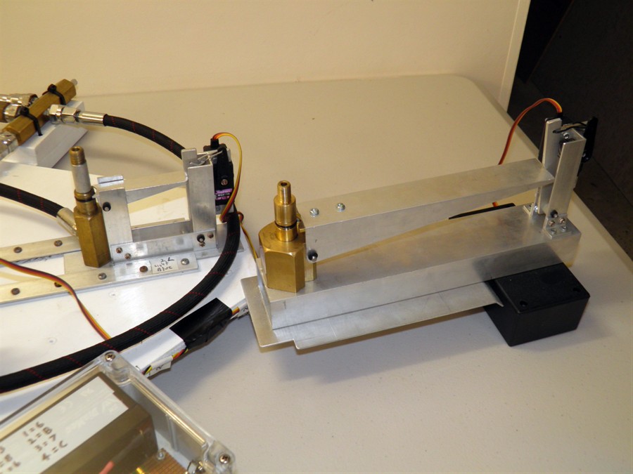
5 January 2015
- Worked mostly on the launcher release
head to fit the lever arm. Lots of filing to
do, this would have been so much easier if
we had a milling machine. With the pivot in
this location, the lever arm has about a
40:1 ratio. This means there is going to be
around 2kg pushing down at the end.
Launcher fitted with lever arm
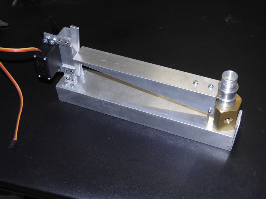
6 January 2015
- Bought more of the 84gsm plain weave
cloth. This looks like the original version
we had so I am keen to see if it will behave
better when we make up the tail-cone and top
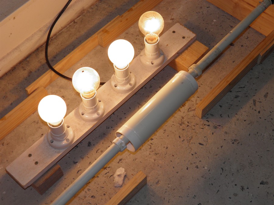
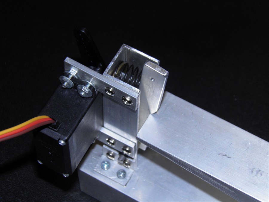
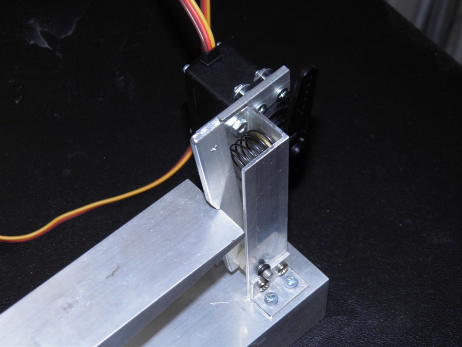
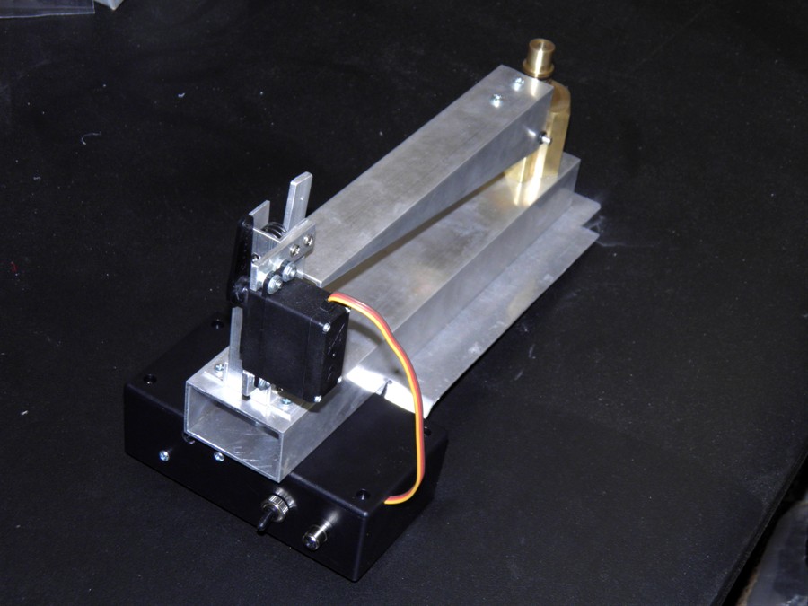
bulkhead. We also continued work on the
launcher. The servo motor has been attached
to the end frame and the small lever was
also made. The mechanism feels nice and
solid but we'll need to do a full pressure test to see if it holds.
End frame with servo motor
attached
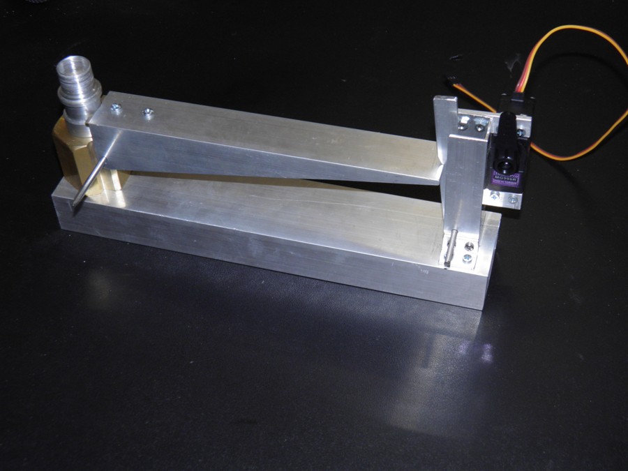
Other side
Lever arm in the released
position
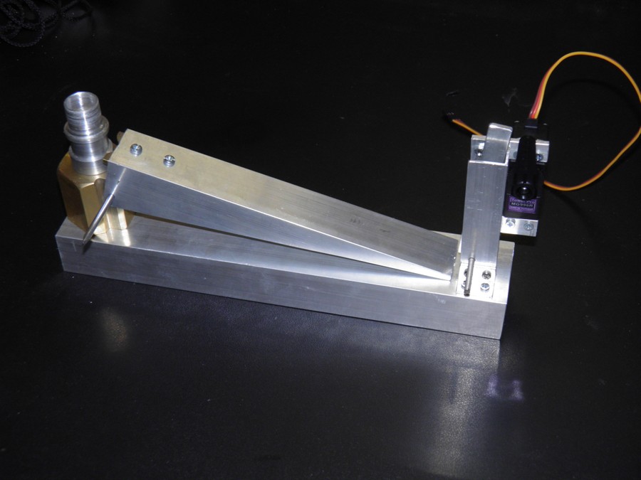
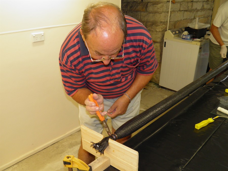
7 January 2015
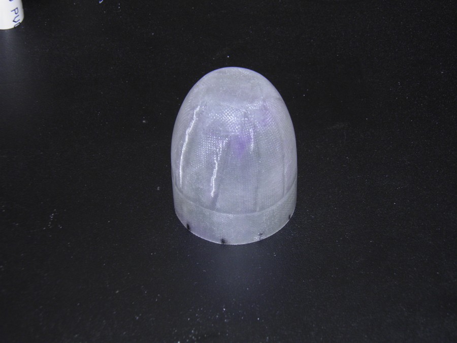
- Made the tailcone and forward closure
today. We used the new cloth for these and
it worked much better. The glass did not
lift off at all. Again we used 10 gores and
a single wrap around the base. We also
worked on the launcher adding the spring,
attaching the pins and small lever. I also
had difficulties driving the servo motor via
the cluster launcher. The new servo didn't
want to move properly. When I tried with a
different servo timer and a 9V battery then
it worked fine. It may simply be a battery
issue and may need re-charging.
Prepping tail cone plug
Tailcone curing
Forward closure curing
30' roll of CF sleeve
Spring fitted to smaller lever
Reverse view
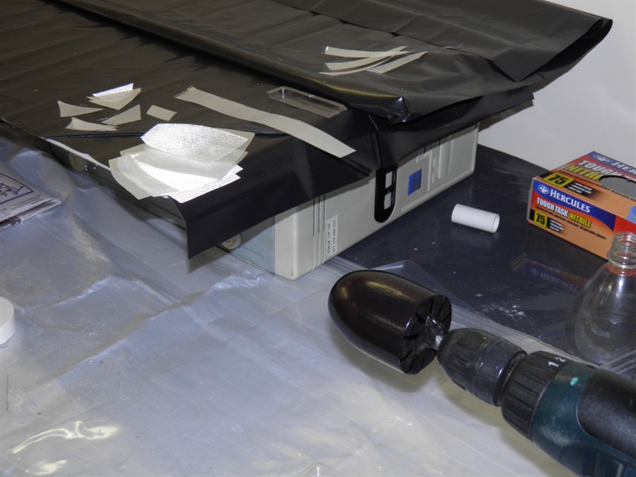
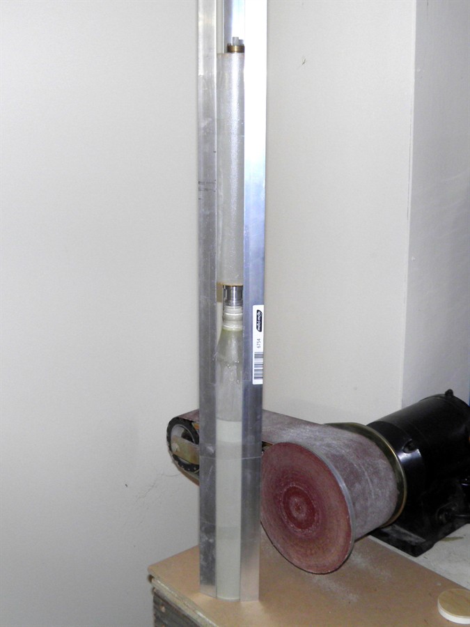
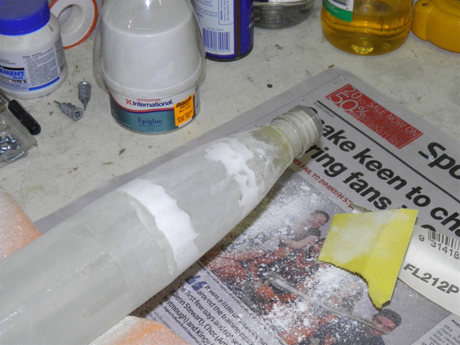
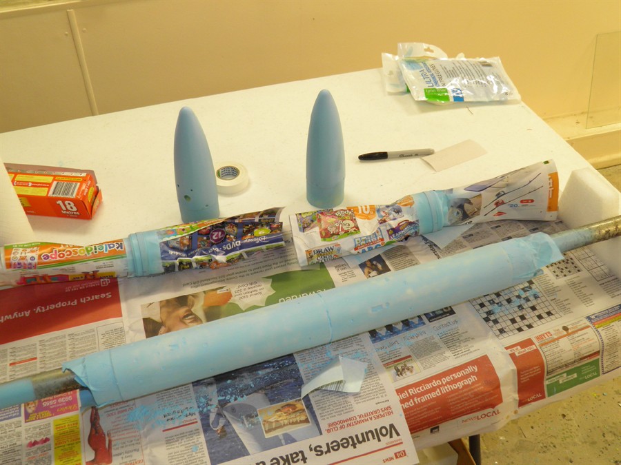
8 January 2015
- We pulled the tailcone and forward
closure off the plugs and sanded them. We
then tried shrinking the forward bottle over
the forward closure on the lathe with the
heat gun, but when it came to pulling it off
there were two cracks that developed in the
forward closure. There must have been a gap
between the fiberglass and the plug and the
fiberglass simply got crushed. We will make
a new one rather than repair it.
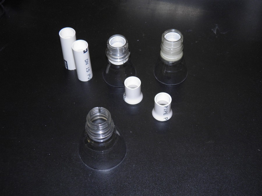
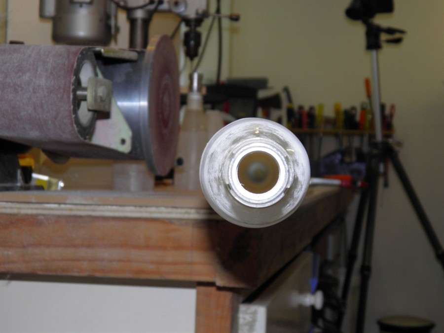
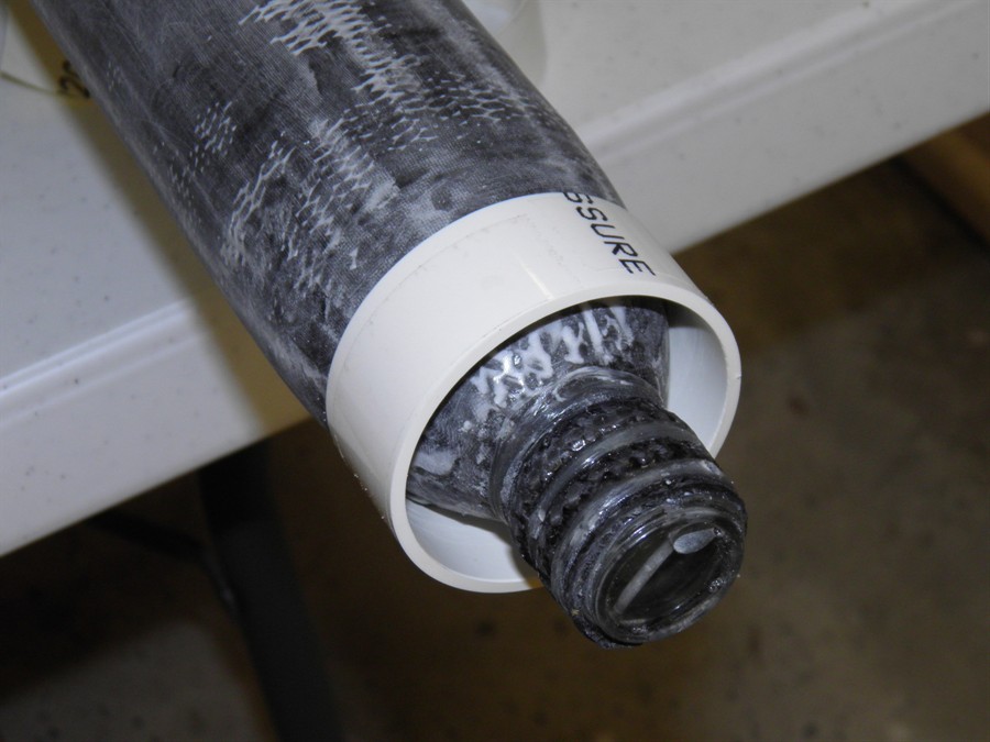
We also made the nozzle insert and after
several goes we finally made one that looks
good. We had to increase the internal
diameter of the PVC to 18.1mm from around
17.8mm so that the thread could be cut and
the nozzle wasn't too tight.
We then shrunk the tail cone bottle over
the insert and tailcone on the lathe. We had
to do this twice as the first bottle neck
was slightly too narrow for the nozzle to
fit in.
We glued the insert into the tailcone bottle
with 24Hr epoxy and removed the flange with
a sanding wheel in a Dremmel tool.
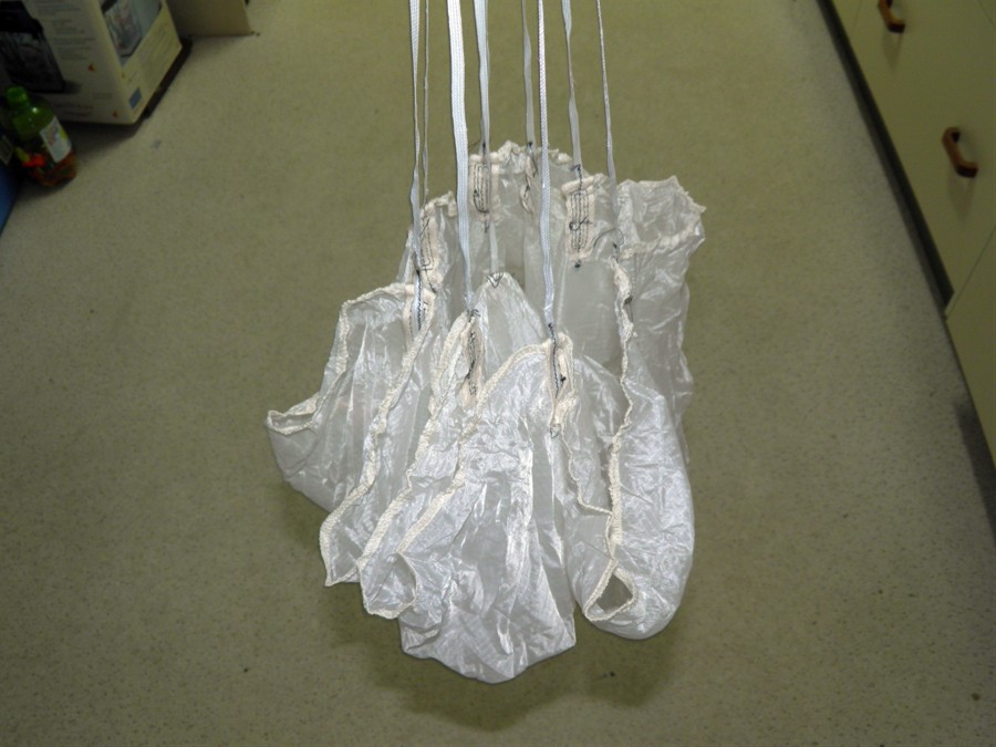
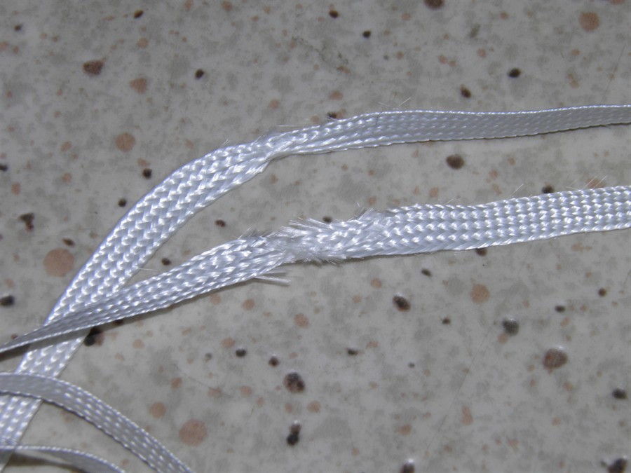
We also received the parachutes from
Aerocon. While the parachutes themselves
look good the shroud lines made from thin
flat braided nylon and look like they have been
through a blender. They have a few cuts, are
frayed in a number of places and are held at
the end with a small metal clip. We are
going to need to replace some of the shroud lines
if not all. We'll see.
Nozzle insert in bottle
top view
Cracks in forward closure
36" Aerocon Chute
Shroud line condition
Deployment bags from 1973!
9 January 2015
- We made up second pair of forward
closure and with the spare glue made the
tail cone. This time we used 11 gores for
each to make them a little stronger as the
last forward closure had a weak spot along
which it cracked when heat shrinking the
bottle over the top.
Making new tailcone and forward
closure
10 January 2015
- Glued the coupler into one of the long
tubes. We also glued the bottles to the tail
cone and forward closure. Using the
left over glue, we glued in the nosecone
bulkheads.
Coupler glued into tube
Weights holding down bottles
Bulkheads glued in for nosecone
couplers.
11 January 2015
- Glued the forward closure and tailcone
to their respective tubes. This makes it
easier to work on both ends and we'll glue
the whole thing together once the ends are
finished.
Launch tube used for alignment.
Bottom of launch tube is in a
centering ring
Forward closure glued into
place.
12 January 2015
- Bought 38mm hinges at Bunnings, as
well as 33 x 300 Al round bar from Edcon
steel to make up a spare nozzle. The hinges
were cut down to size with the Dremmel and
cut off wheel. We also bought polyester
ribbon to replace the nylon shroud lines. We
weren't able to easily source the nylon
cord, but the polyester looks like it may
work.
13 January 2015
- Applied filler made up of epoxy and
microballoons to the rough interfaces
between the glued sections on the tailcone
and forward closure. My wife picked out the
threads from the shroud lines so they can be
re-sewn. She managed to do it at least 3
times faster than what I would have been
able to do.
Glued and sanded
Filled with microballoons/epoxy
same for the forward closure
14 January 2015
- Sanded the tailcone and forward
closure interfaces smooth. Worked on the
grapple arms for the deployment mechanism.
These are now attached along with the hinges.
New grapple arms closed
Grapple arms open
Another view
Filled and Sanded
15 January 2015
- We glued the two pressure chambers
together today. We used 3 aluminium L
brackets held on with rubber bands to keep
the joint aligned. We also made up another
forward closure using 10 somewhat wider
gores and a single wrap at the bottom. We
also made up a new full length tube using 4
wraps of the new 85gsm cloth. The previous
11 gore forward closure was too tight a fit
in the tube and required a lot of sanding.
We also glued another PVC ring to the balsa
sandwich bulkhead and glued the centering
ring to the electronics tube.
Two halves sanded and
ready for gluing
Gluing the two halves together
using Al brackets for alignment
New forward closure
New full length tube
16 January 2015
- This morning we discovered that the
tail cone section was glued in slightly
crooked. Although we had the launch tube
going through a centering ring at one end of
the tube and the other end going through the
nozzle, the whole section had tilted
slightly. Weighing up the options we decided
to cut off the tail section and glue in a
new one. At the kinds of speeds and forces
we are dealing with here we could be in a
lot of trouble if we are out a degree. We'll
lose a few cm of length, but we'll also lose
a bit of weight. We'll make up an alignment
jig with the angled brackets to align the
nozzle and tail section better.
We pulled yesterday's tube off the
mandrel. A pair of new nozzle
inserts and tail cone bottles were also made
up. These were then glued together
with the 24Hr epoxy.
Gluing inserts into bottles
Here you can see the misaligned
tail cone
17 January 2015
- We rolled another full length 4 wrap
tube. We also made up the replacement tail
cone. We glued the nozzle insert onto the
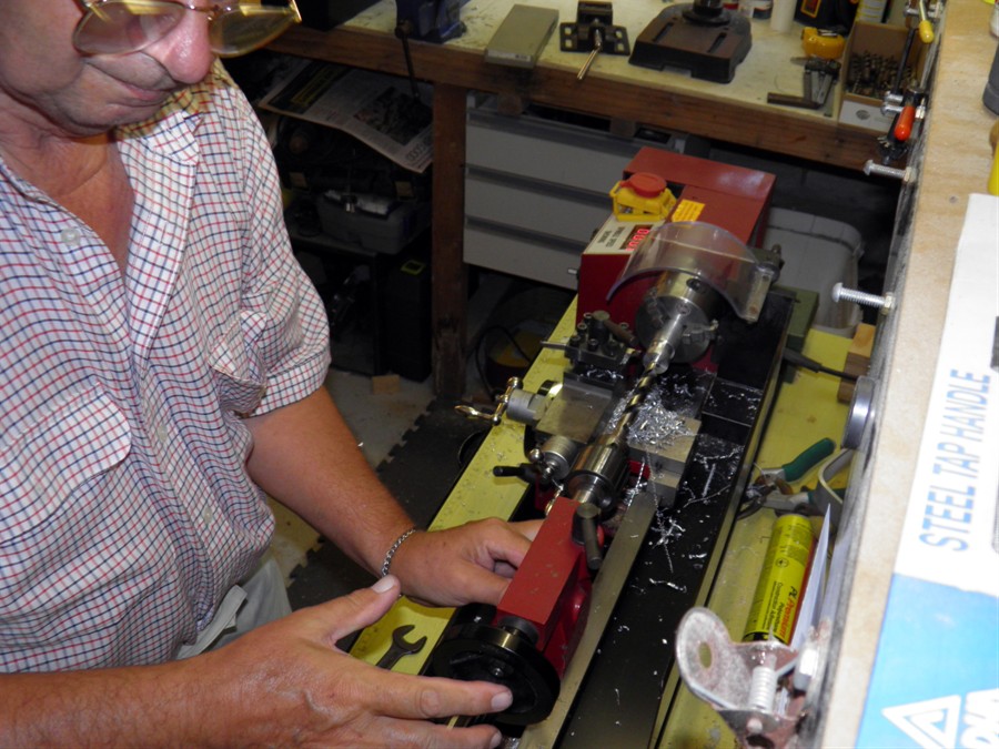
previously made tailcone. Dad also machined
up a new second nozzle. We also had the two
scuba tanks refilled today. We will use them
for testing over the next few weeks and get
them re-filled again for the trip.
Machining nozzle
More nozzle work
Gluing bottle to tailcone
making up a replacement tailcone
18 January 2015
- Made the nozzle alignment jig today.
This is basically a cylinder of the rocket
diameter with a short length of launch tube
right down the middle. This gets inserted
into the nozzle and the aluminium brackets
hold the cylinder aligned with the rest of
the rocket. We cut the misaligned tailcone
off the rocket and used the new jig to align
the new tailcone.
We also trimmed the full length tubes and
glued the coupler into one of them. The top
closure also had the bottle glued to it as
did the second tailcone. The second nosecone
had it's little ball glued into the nose.
Lastly we cut off a second length of the
electronics tube and glued a centering ring
to it.
Nozzle alignment jig in place
while gluing
in the tailcone.
Gluing the bottle to the forward
closure
19 January 2015
- When we were about to glue the #2
tailcone into the long tube we discovered
that the nozzle and bottle weren't quite
aligned at the top of the fiberglass
tailcone. The bottle must had been shrunk at
a bit of an angle. While there is some give
in the tailcone to tube join it wasn't
enough to correct the deviation with the
nozzle alignment jig. So we opted to build a
whole new tail cone ... again! This was going to push
the schedule back a little but there is
still time. I was able to peel off the
bottle and nozzle insert from the original tailcone that was cut off so that will save
a few hours work and at least a day in
waiting for glue to dry.
We glued the forward closure to the long
tube. With the spare glue we glued a few
more small components on the deployment
mechanism. We also cut out 11 gores for the
new tailcone and made up the tail cone on
the plug.
20 January 2015
- After sanding, we glued the nozzle
insert and bottle onto the tailcone. We
also continued with making of the deployment
mechanism. The holes for the nosecone as
well as the payload bay were tapped. We did
the first tests with the deployment
mechanism and one set of rubber bands. We
may need to add a second rubber band or
replace existing ones with stronger ones.
21 January 2015
- We glued the tailcone into the long
tube. We also tested the deployment
mechanism with stronger rubber bands. They
seem to be working well and I think we'll
probably go with those.
Nozzle alignment jig
22 January 2015
- We continued work on the second
deployment mechanism grapple arms. We also
fitted a servo motor into the second
electronics tube.
23 January 2015
- Today we glued the #2 two long tubes
together and again let it rest vertically.
We also made up the grapple base and cut the
hinges to size and attached everything to
the nosecone bulk head.
24 January 2015
- We bought some Epiglue today to see if
it is good at making fillets as they say. We want to
use it for the fin fillets or as general
filler.
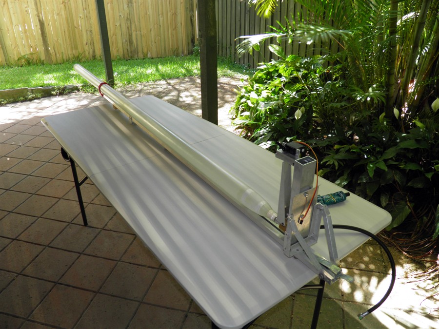
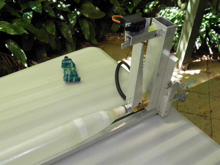
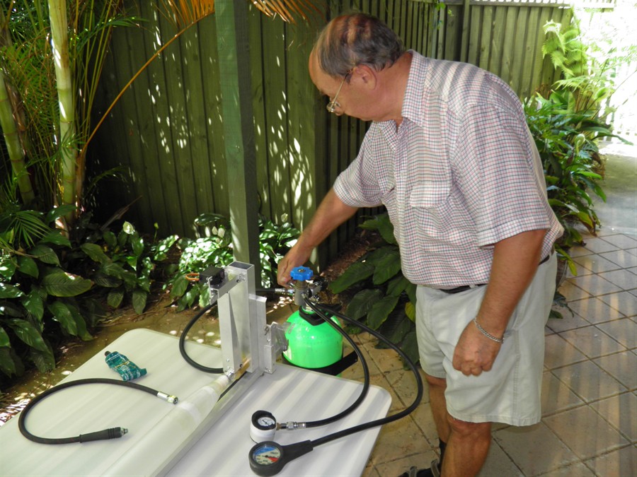
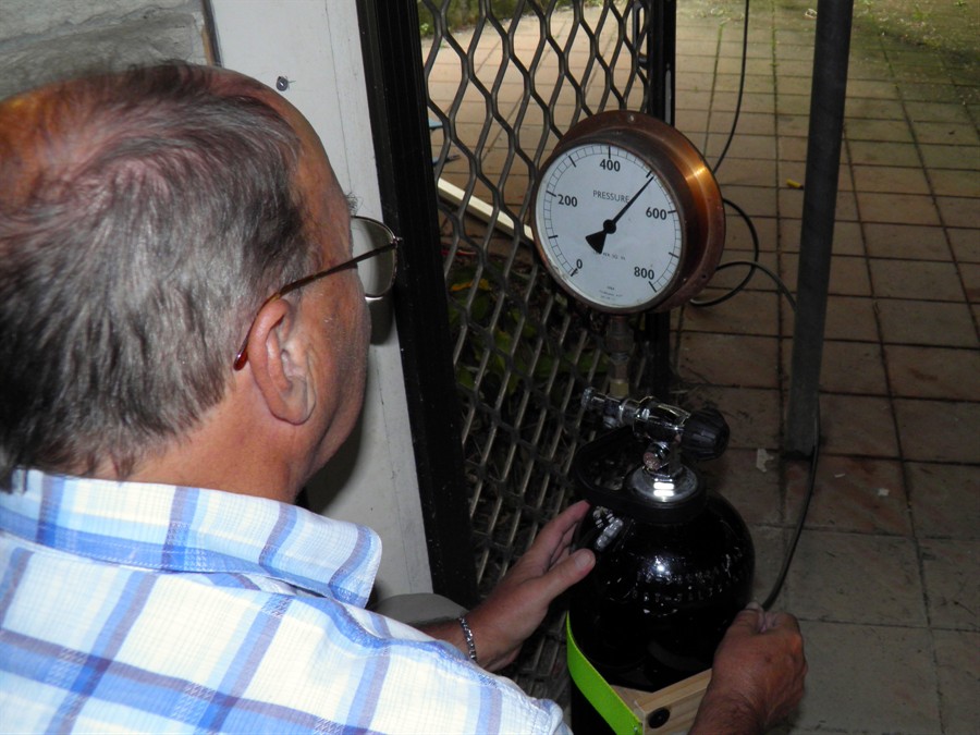
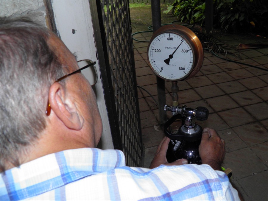
We also did a leak test of the #1 and #2
pressure chambers to around 20psi to make
sure there are no tiny holes like we saw
with the test pressure chamber. Both
chambers came up well and passed the leak
test.
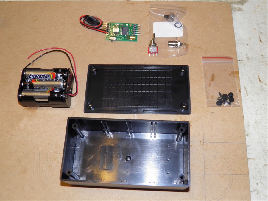
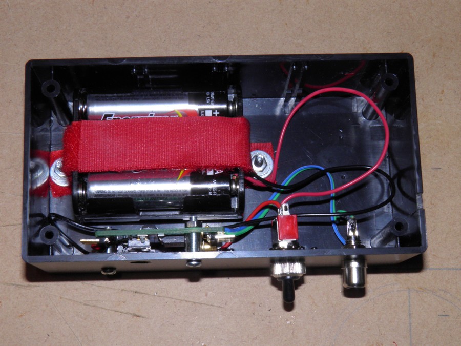
We also made up the control box for the
launcher and mounted it under the servo
motor. We are using 6 x AA batteries rather
than a 9V battery in case we need a little
more current when operating the larger
servo. The control box just has the battery
pack, a servo timer II set to 0 time, a
switch with a water proof hood and an RCA
connector to connect the remote trigger
switch.
Getting ready to do leak test
Using the launcher to connect to
rocket
Pressurised to 20psi
Both #1 and #2 check out OK
Launcher control box components
Launcher assembled
Control box mounted under
launcher
Gluing in thermocouple
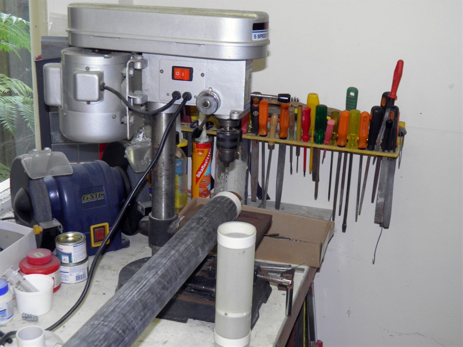
25 January 2015
- We sanded the rockets down getting
rid of any bumps. One of the places where we
glued the coupler in the middle of the
rocket dried with a decent sized bubble. So
we drilled (by hand) through the first layer
with a 1mm drill and used a syringe to
squeeze the epoxy into the void. This worked
quite well and reduced the bubble greatly.
The epoxy when cured came out of the syringe
very easily.
We also glued the PVC ring into the
nosecone as well as the second bulkhead on
the #2 payload bay.
Rocket being sanded prior to
having sleeve applied
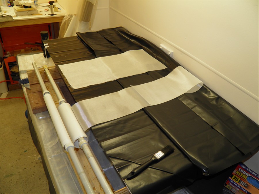
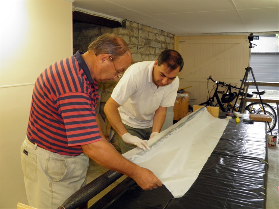
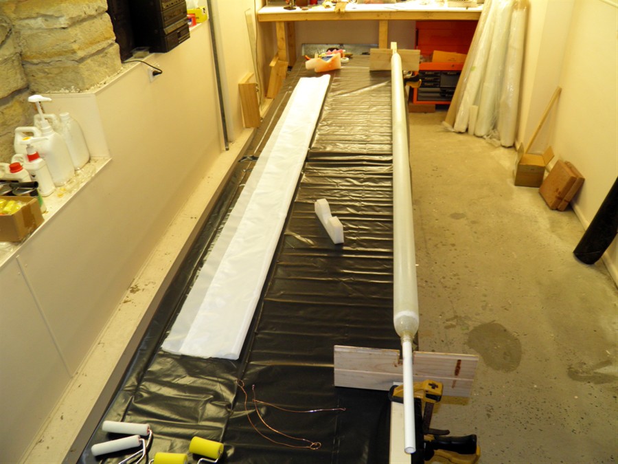
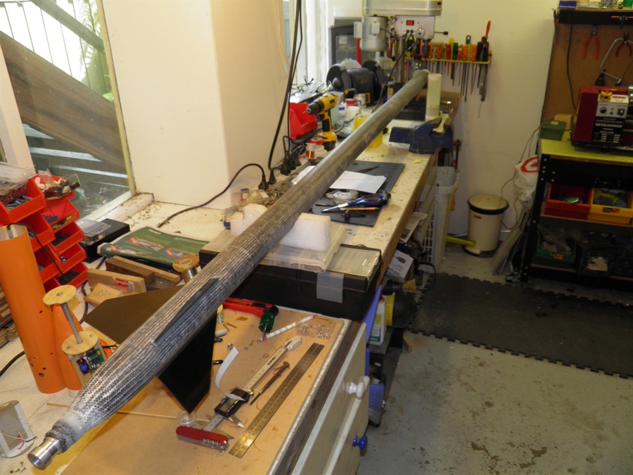
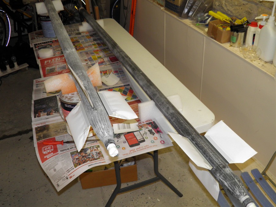
26 January 2015
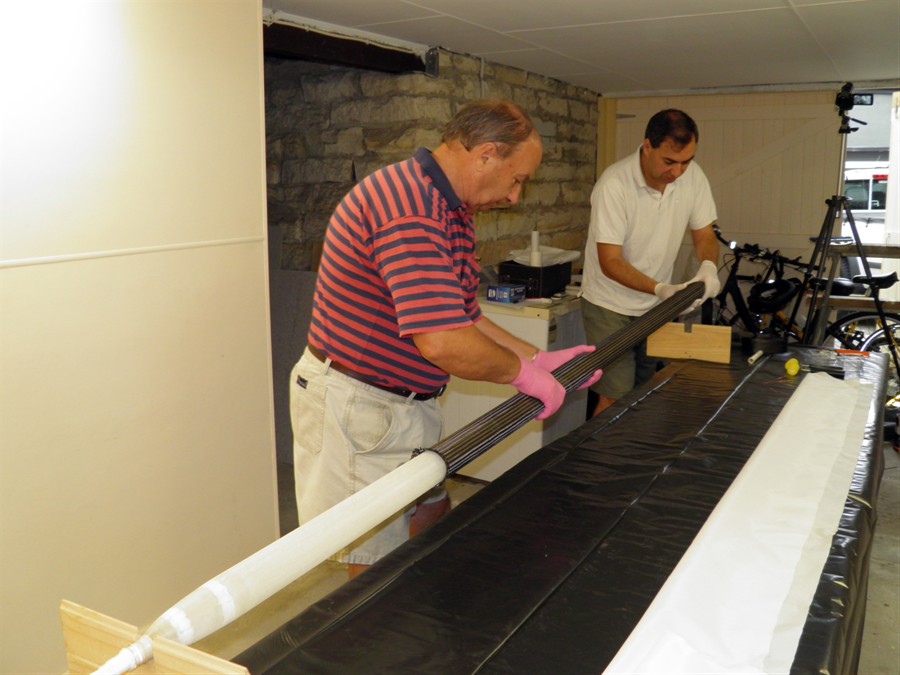
- We finished sanding the rocket ready
for gluing the sleeve on. We spent a bit of
time prepping everything to be ready to glue
the sleeve on. Once you start gluing you have
to finish the whole job. Nic Lottering gave
us some good tips about how to carry
out the process. We ended up using mohair
rollers rather than the foam rollers we
normally use. We put the sleeve on dry and
then used the rollers to roll out the epoxy.
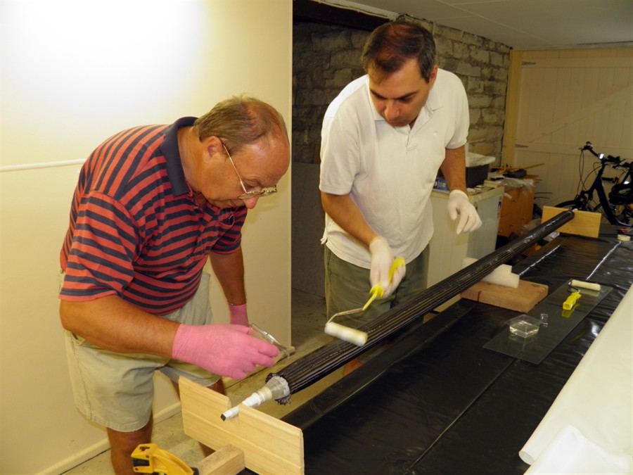
We had just enough time to finish the whole
job before the glue started to gel. My wife
helped mix epoxy as we went while dad and I
did the pouring rolling. My sister helped
take photos and video of the whole process.
We hadn't fully stretched the sleeve initially
to allow for gaps between the weave and
hopefully allow the glue to penetrate. About
half way through the process we finally
stretched the sleeve as far as it would go and
continued to roll on the glue. Once it was
nicely soaked we tied the ends down with
wire to hold the sleeve in place. Then we
quickly applied two wraps of peel ply and rollered that on with a couple of the foam
rollers. This worked well to soak up the
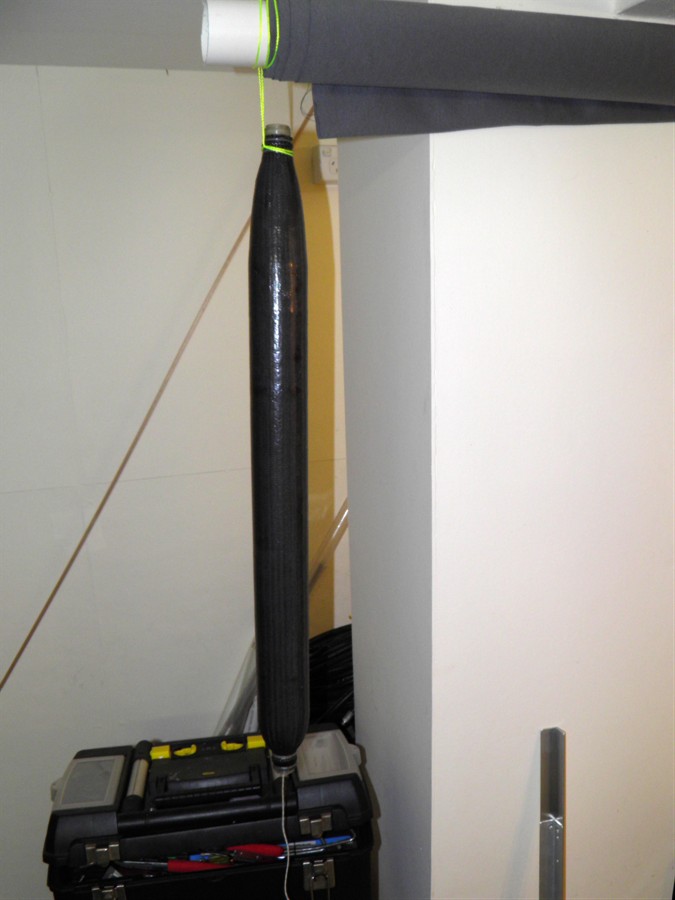
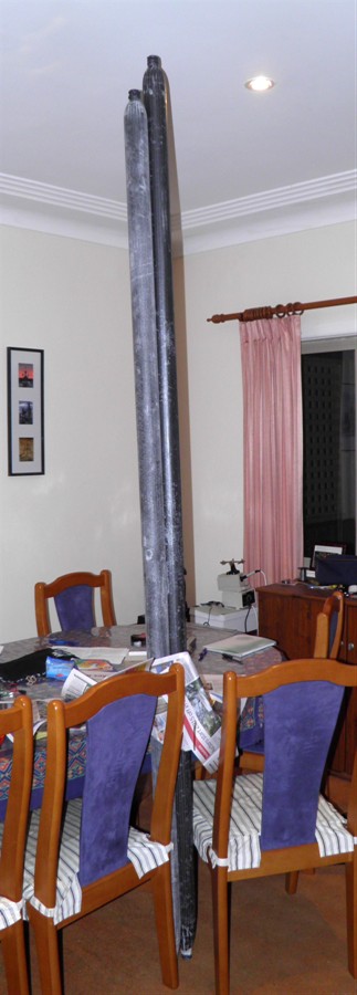
extra glue. When it was all finished we
stood the whole rocket up on its end to
prevent it from curing like a banana.
Mum also finished sewing the new shroud
lines to the parachute and it looks like
they are going to work well.
Putting on sleeve
Rolling on epoxy
Tying wires on the ends
Applying peel ply
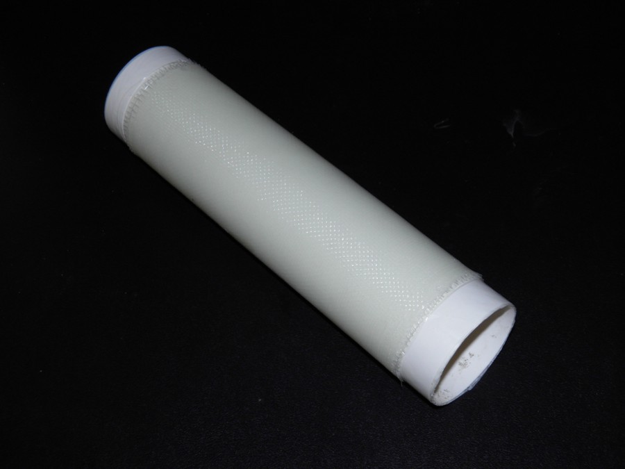
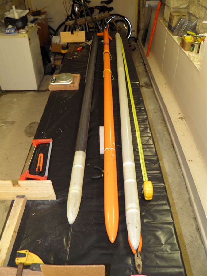
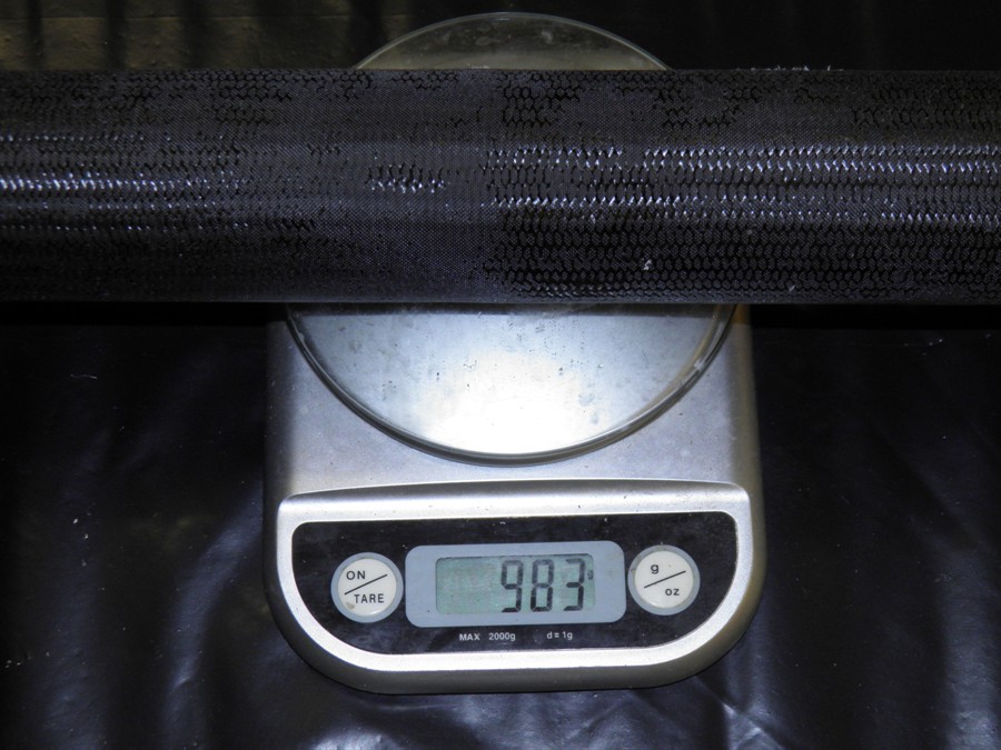
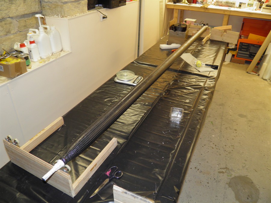
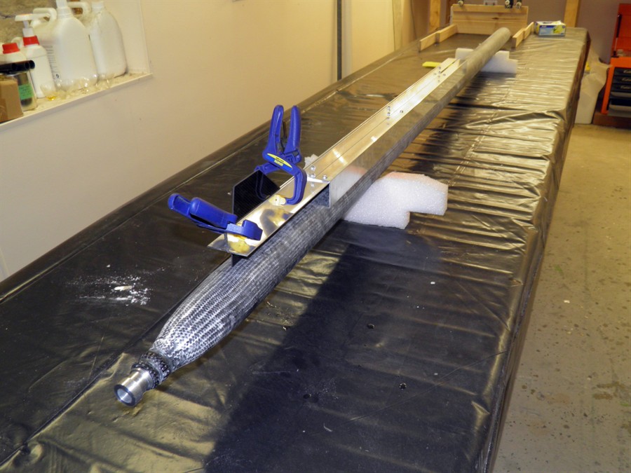
27 January 2015
- We peeled off the peel ply and trimmed
the ends of the CF sleeve. It was evident that
more glue was needed in some areas, so we
will go back and fill those in with another
coat of epoxy. The sleeve otherwise looks good
and the whole pressure chamber weighs 983
grams. Shadow by comparison is almost the
same length and with nozzle and fins weighs
1096 grams without the deployment mechanism.
We also finished up working on the #2
nosecone and grapple arms as well as
mounting the #2 payload bay.
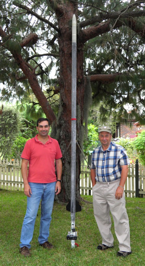
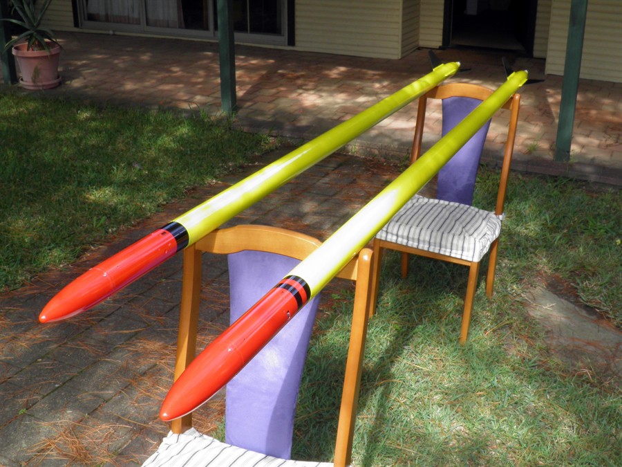
#1, Shadow and #2
meet for the first time
Raw weight of pressure chamber
before
being filled in
New grapple arms attached to #2
28 January 2015
- Worked on #2 deployment mechanism
finalizing nosecone and grapple arms as well
as mounting the payload bay.
29 January 2015
- We filled some of the holes in the
pressure chamber with more West Systems
epoxy and placed the whole rocket on the
rotisserie. We used 2 pumps and the foam
roller to get the epoxy on. We then also
used a scraper to try to spread some of the
glue out more evenly. We wanted to use
the thin stuff to penetrate any fibers that
weren't properly wetted out during the
original layup. Next we'll use the west
systems with microbaloons to fill in the
remainder of the divots. We also wrapped the
ends of the pressure chamber with glass
fibers to replace the original wire used to
hold the sleeve down.
We also reprogrammed the Servo Timer II's
to add 5 seconds to all delay timing
settings. The 12 second limit of the normal
Servo Timer was not enough.
Applying extra epoxy on top to
fill holes
Sanding tailcone
30 January 2015
- We applied filler to gaps in the #1
pressure chamber. The filler was just a mix
of West Systems epoxy and microballoons in a
toothpaste consistency. This was applied
using a scraper made out of a piece of
plastic,
Dad picked up some more peel ply from
Nuplex as well as we have now run out.
1 February 2015
- We covered the #2 pressure chamber
with the carbon fiber sleeve today. The
process was a lot smoother as we knew what
we were expecting, and having put on more
epoxy meant that the gaps were filled out
better. We also had patches of peel ply
ready for the curved end sections and those
were then wrapped with electrical tape to
press them down against the tube.
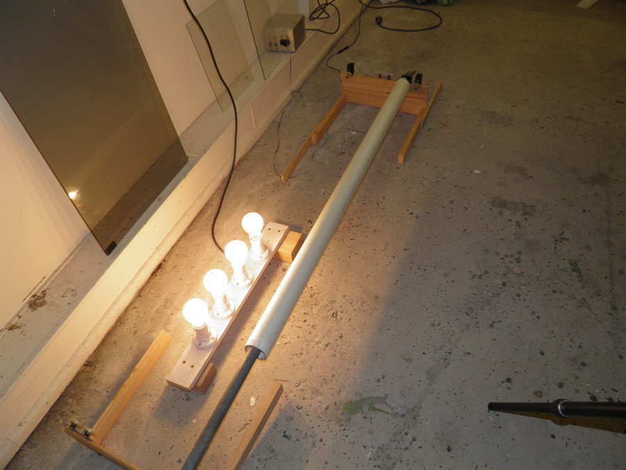
We also did a thermal pressure test on the
test chamber to see how much temperature
increases inside the pressure chamber. The
temperature needs to stay below about 60
degrees C to make sure we don't
significantly weaken the epoxy. During the
test we started at 19 degrees C and
increased the pressure at normal speed and
the rocket reached a temperature of 38 C
when we reached 200psi. Leaving the pressure
chamber at that pressure made the rocket
drop at least 10 degrees within about 1
minute. The rate of cooling was significant
and we'll probably do a fill and hold
scenario to give the rocket time to cool.
Letting the air out through the pressure
release valve made the temperature drop to
0C.
Repeating the experiment to 200psi but
this time significantly faster raised the
temperature to 45 C. Again the temperature
decreased fairly quickly after pressure
stabilized.
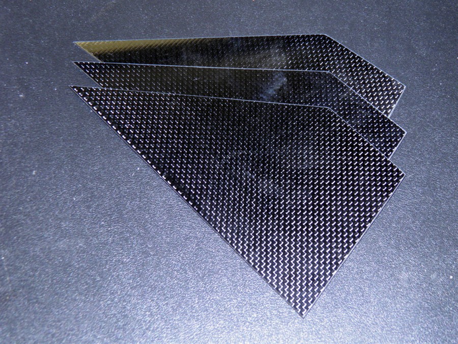
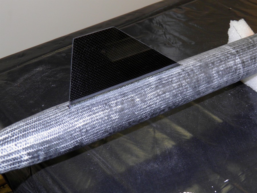
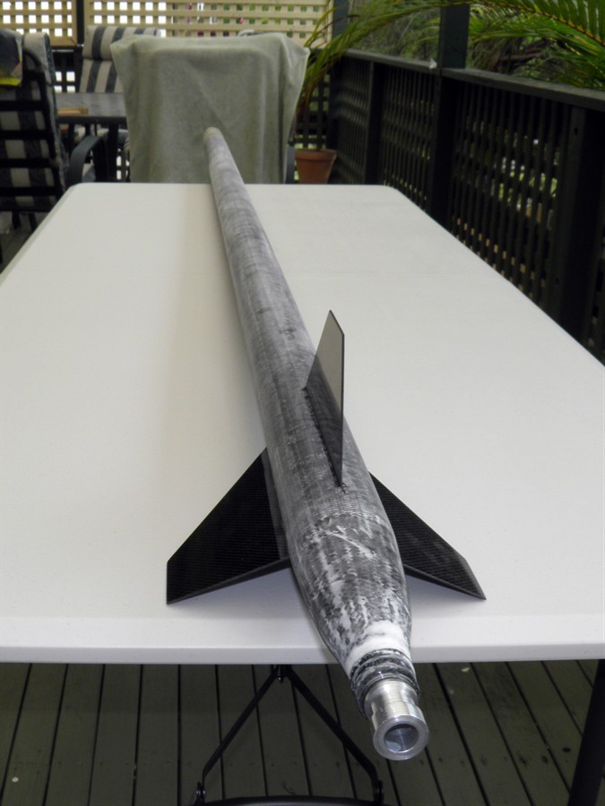
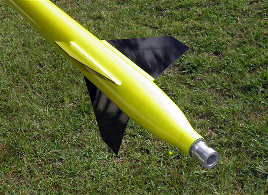
Lastly we cut out three fins from the
1.5mm CF sheets from hobby king. The sheet
cuts well but it blunted the saw blade
fairly quickly.
Getting ready to put the sleeve
on
Ambient temp
Pressurised to 200psi quickly
Pressure released
2 February 2015
- We pulled the peel ply off the #2
pressure chamber. This is always a lot more
work than expected, but in the end it came
off fairly cleanly and the finish is a lot
better than #1. We won't need to do a second
coat of epoxy, we'll just go straight to the
filler, although we may make it a little
more runny and then put the whole thing on
the rotisserie.
We also sanded down the #1 pressure
chamber with 120 grit paper to remove all
the lumps and bumps. Other than filling the
top with epoxy the pressure chamber is ready
for hydro testing. We'll wait a few days for
#2 to fully cure before pressure testing
both at the same time.
Peel ply has been peeled off.
3 February 2015
- We filled in the #2 pressure chamber
with epoxy/microballoon mix and again
scraped it down with a piece of plastic.
This time we used a slightly thinner mix to
help it penetrate a little better. This took
just one pump. We also wrapped the ends in
fiberglass tow to replace the wire we
removed.
4 February 2015
- We filled the top cavity of the
forward closure with epoxy. This provides
support for the forward seal. It will be
drilled out a little later so that we can
put a pin in and attach the shock cord.
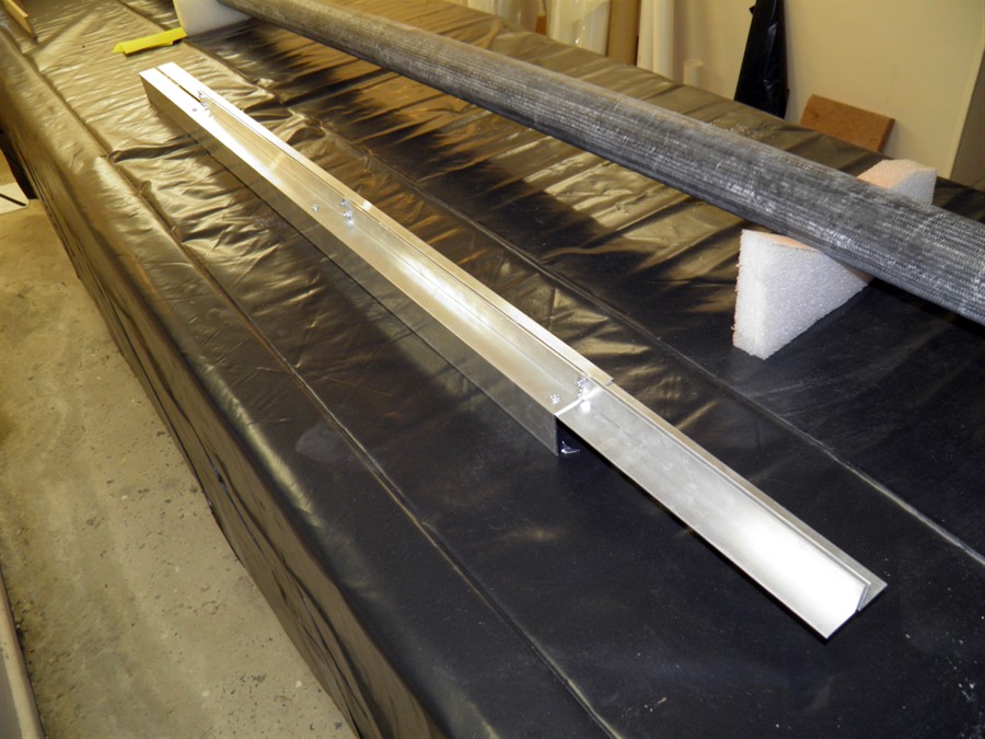
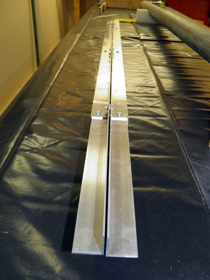
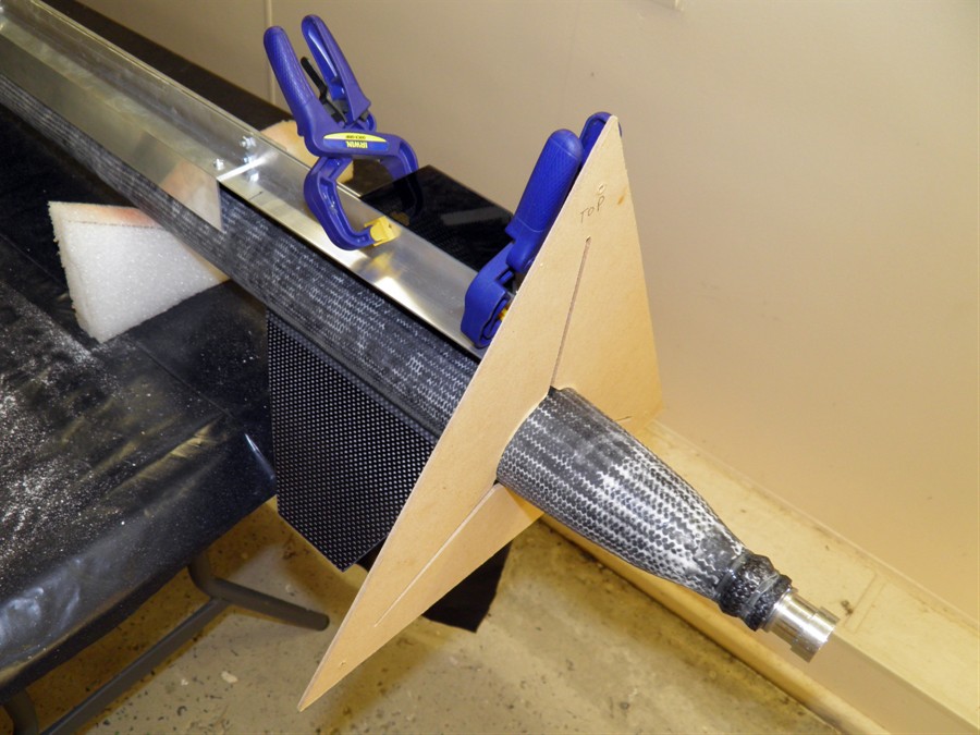
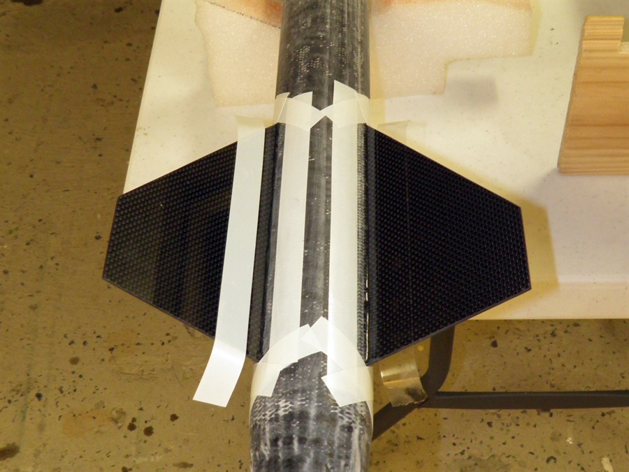
We also made the fin alignment jig. This
is just made out of a number of aluminium
brackets screwed together. It just sits on
top of the rocket to keep the fin aligned.
The fins will be tacked on with 24Hr epoxy
and then fillets will be made with Epiglue.
Filling tops with epoxy
Fin alignment jig
Gap is set to width of fin
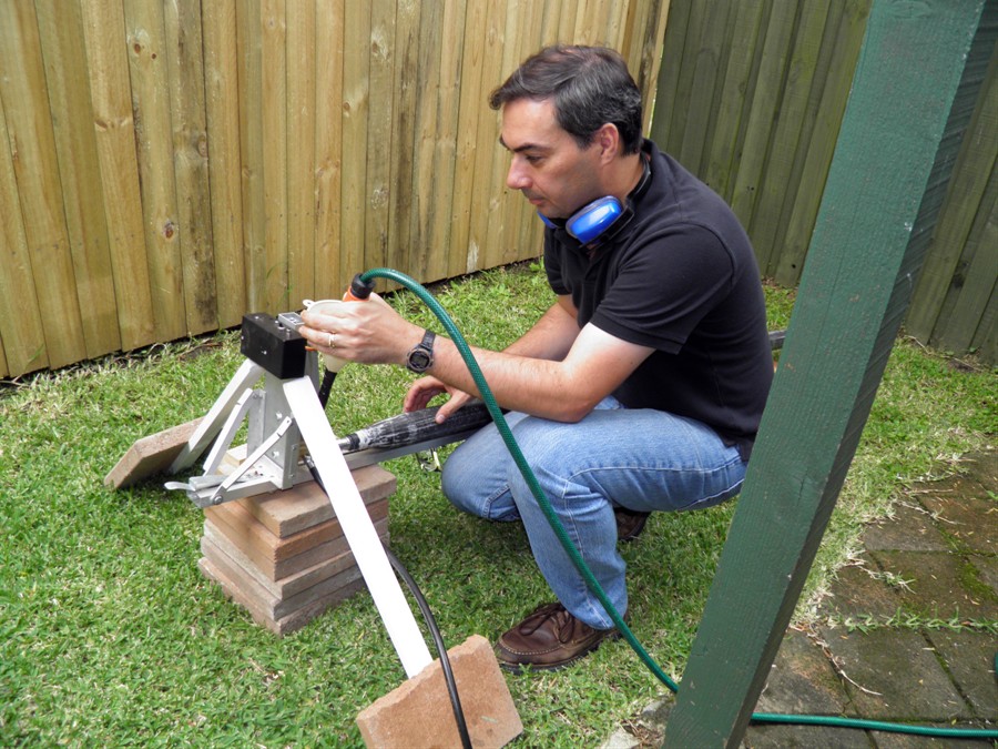
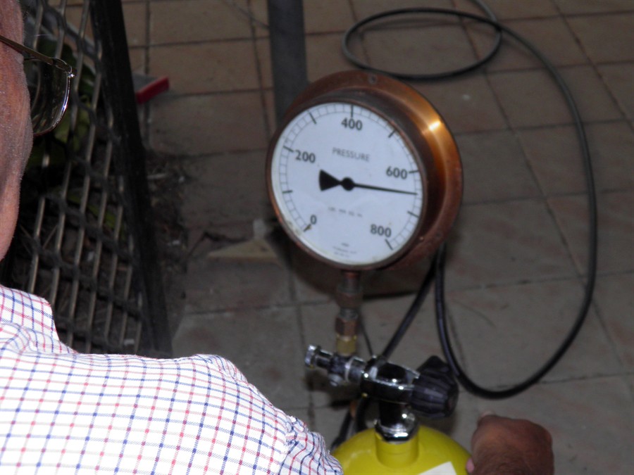
5 February 2015
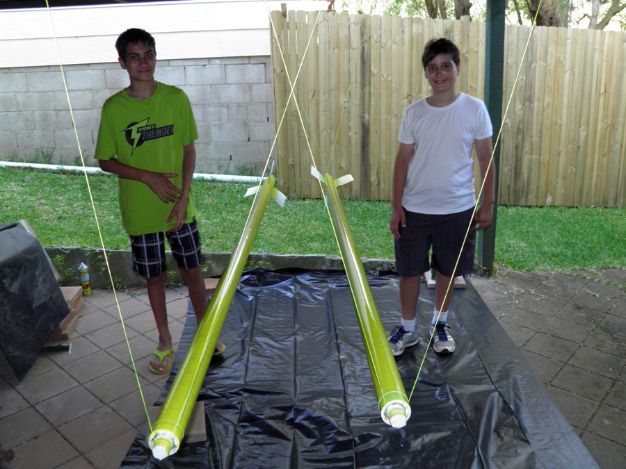
- Big milestone today. We successfully
pressure tested both pressure chambers to
515psi. This now allows us to attach the
fins and forward mounting ring. We also
measured the total capacity of both
chambers. #1 is 6.77L and #2 is 7.06L We
also weighed the two and they came in a
little heavier than what we were hoping for,
but I suspect next time if we use vacuum
bagging to squeeze out more epoxy,
that weight should come down a little more.
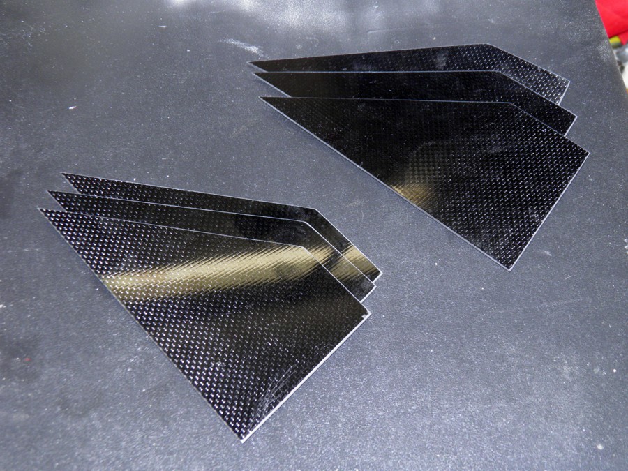
We also cut out the 3 remaining fins for
#2. These are now ready to glue on.
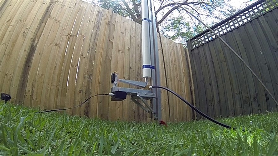
Pressure test setup
Launcher is supported to prevent
it from
tipping over
First set of fins
Second set of fins
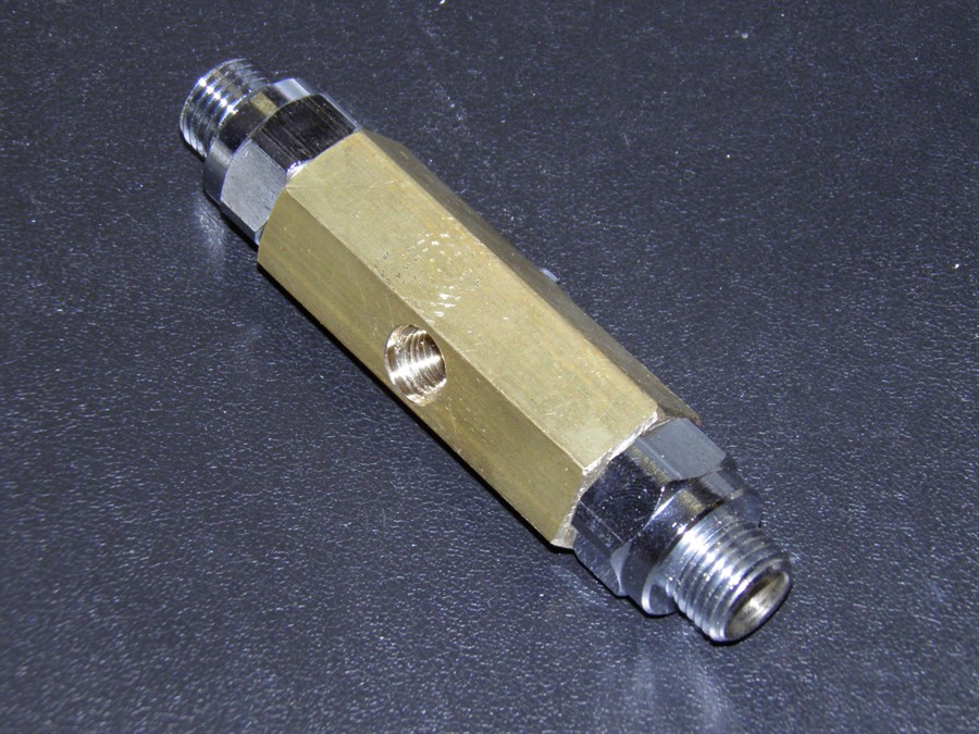
Scuba hose adaptor
#1 tested to 515psi
Filling #2 with water for hydro
test
#2 tested to 515psi
6 February 2015
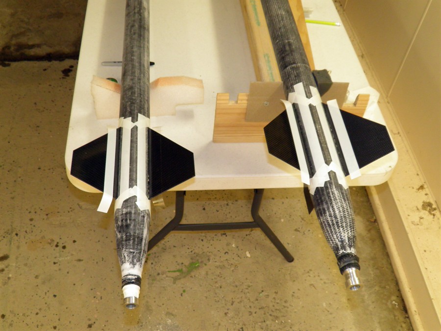
- We attached the first fin today to #1.
7 February 2015
- We attached the second and third fins
to #1 and took a while to sand down #2. We
then made a pair of PVC rings from the same
material the mandrel is made off. One
internal edge was bevelled as that will sit
up against the pressure chamber. After these
are glued in place we will tap 8 holes
around the circumference.
We also did a little more work on the #2
deployment mechanism making the servo access
holes. The camera was also mounted in the
nosecone of the rocket on a block of foam.
Access holes for the lens and switches was
also cut in the nosecone.
Lastly we drilled a small hole in the top
closure bottle neck of #2 and then drilled a
second larger hole from the end that will
hold the shock cord loop. A pin gets pushed
into the small hole and holds the shock cord
in place. The pin is then held down with
tape to prevent it sliding out. When it is
inside the electronics tube the pin cannot
slide sideways.
We now have 2 pins + 1 spare.
We used the shadow fin alignment
jig to
ensure we had 120 degree
separation between fins
Test assembly on launcher
8 February 2015
- We attached the first and second fins
on #2.
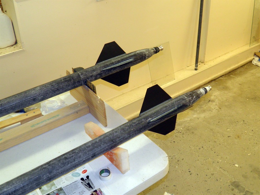
9 February 2015
- We attached the third fin to #2 and
added a pin to the top of #1 to attach the
shock cord. We then masked off the fins and
added two Epiglue fillets to each of the
rockets. We used 8ml of Resin and 4ml of
hardener which was just enough but we should
mix up 9-10mL next time.
Taking photos for GYBTT article.
Adding masking tape for fillets
Both rockets were done at the
same time
Epiglue fillets
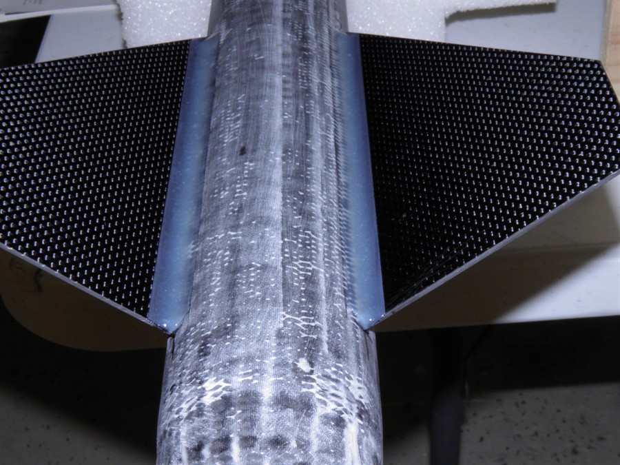
10 February 2015
- We masked off the fins with electrical
tape and then used Epiglue to make the
fillets. We use a short piece of PVC pipe to
smooth them out and give them the correct
shape. When we are done we remove the
masking tape from around the joints which
allows the masked edges to cleanly separate
and the edges become somewhat more rounded
then when the tape is removed after the glue
has cured. We managed to do a set of 8
fillets during the day, 2 at a time on each
rocket.
We also discovered that the nosecone on
#2 didn't sit quite right and was tilted at
a slight angle. We pulled out an old
record player and put the entire payload and
nosecone on it to see how much it wobbled as
it spun. We sanded the lower edge of the
nosecone to level it out, but some of the
holes for the attachment will now need to be
re-done.
11 February 2015
- We tacked on the PVC ring to the top of
the pressure chamber that will hold the
payload bay in place. Luckily Epiglue
doesn't drip and so we were able to glue it
in place on it's side, We used 3 angle
brackets to keep the ring aligned with the
rest of the rocket.
We also cut new shroud lines to length for
#2. These will be again sewn on to the
parachute.
Tacking on PVC ring
Using payload section body for
alignment
3 aluminium bracks used to keep
everything aligned.
12 February 2015
- We tacked on the top PVC ring for #2,
and then filled in the spaces with the extra
glue under the #1 ring. We then sanded the
tail section and smoothed out the leading
and trailing edges of the fillets on the
fins.
PVC ring for mounting payload
section
13 February 2015
- We attached the top PVC ring to #2 with
Epiglue.
14 February 2015
- We tapped M3 holes in the PVC ring #1 and #2 to support
the payload bays.
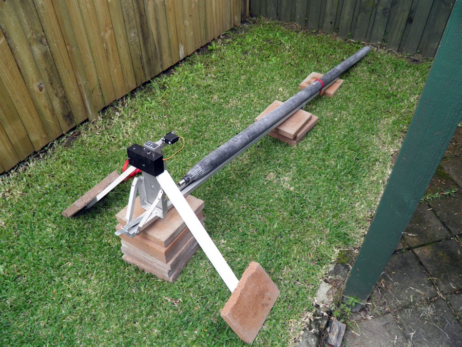
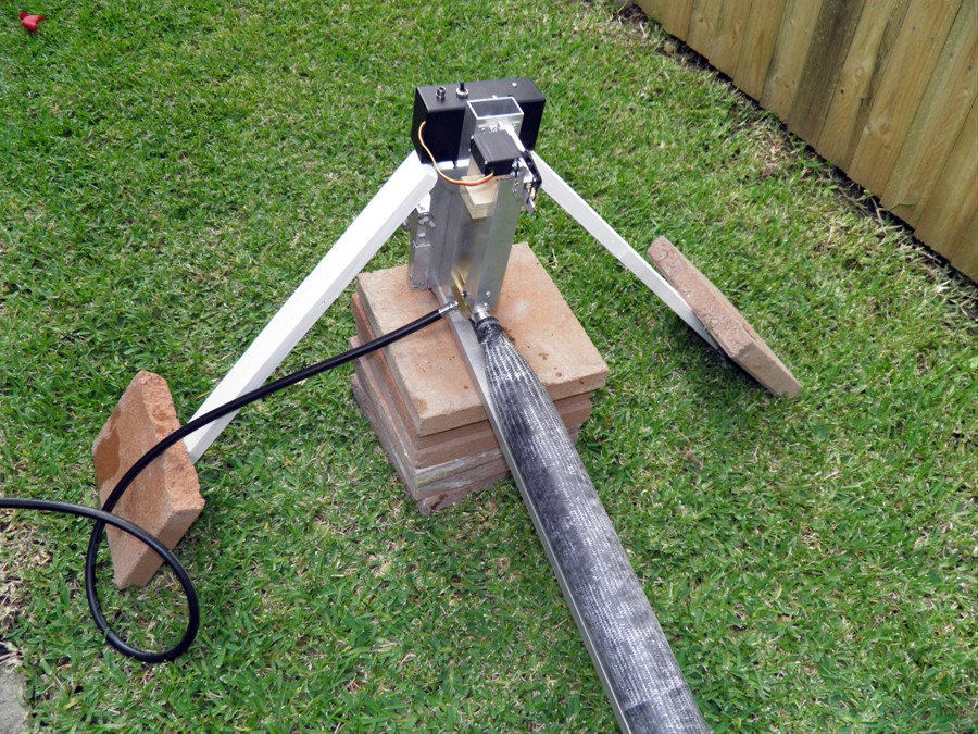
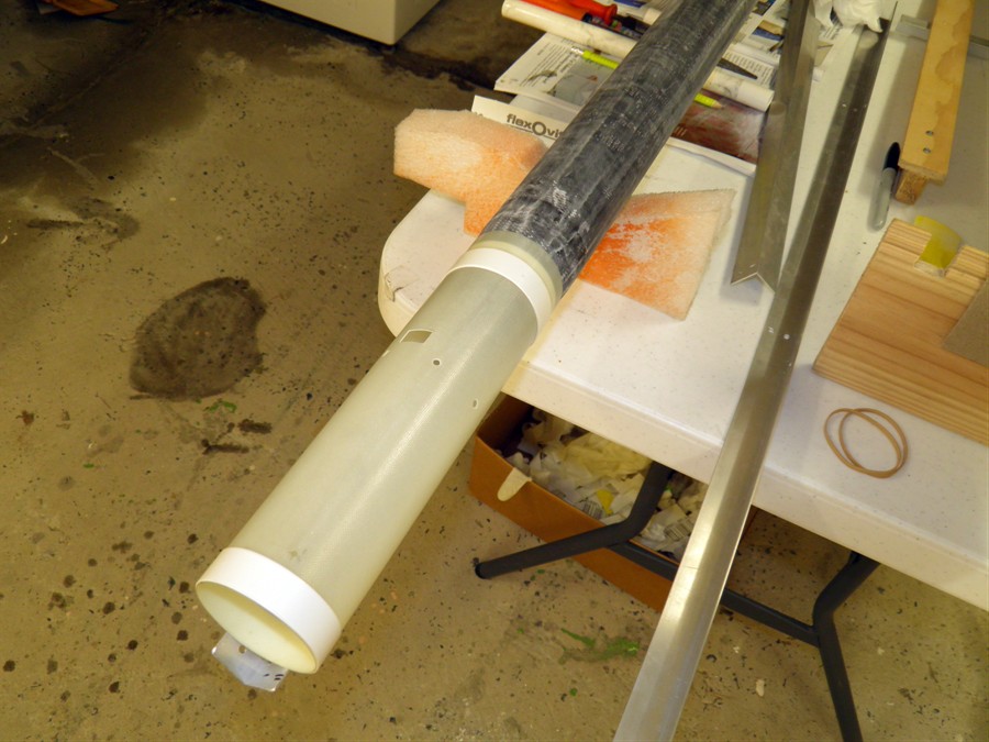
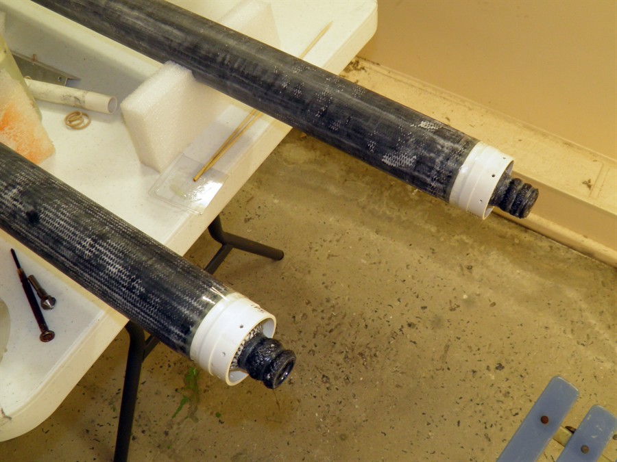
Because we wanted to test the launcher at
full pressure we machined up a plugged
nozzle out of aluminium. In order to catch
the nozzle we mounted a PVC pipe filled with
rags, newspapers and tissues just above the
launcher. We did 2 release tests at 600psi
and 650psi. Both went well but there were
dents on the nozzle where the launcher had
released it.
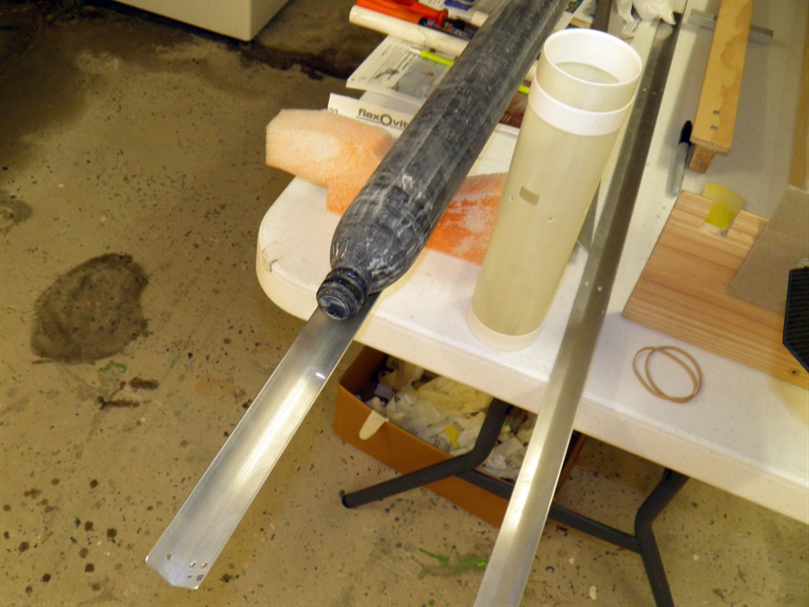
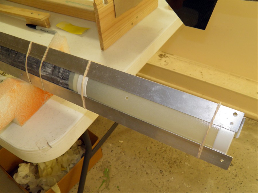
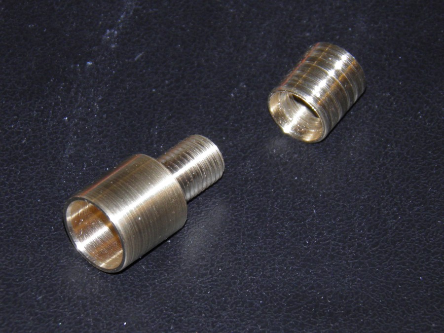
We also machined up an adaptor for the
launch tube and a launch tube insert so that
we could screw the two together when needed
and unscrew them for easier transport. These
were glued in place with the super strength
epoxy.
We weren't sure that the way the payload
section was mounted would hold up to the G
forces on launch so we shortened the payload
section tube so that that the electronics
unit would sit on top of the PVC ring. The
electronics unit has 6 screws holding it in
place, and the payload section has 8 screws
holding it in place. At 60G the entire
payload mechanism would exert about 18Kgf on
those screws, and although the bottom of the
tube was resting against the top of the
pressure chamber, it was resting against the
tapered side of the chamber. There was the
danger that the tube would be forced onto
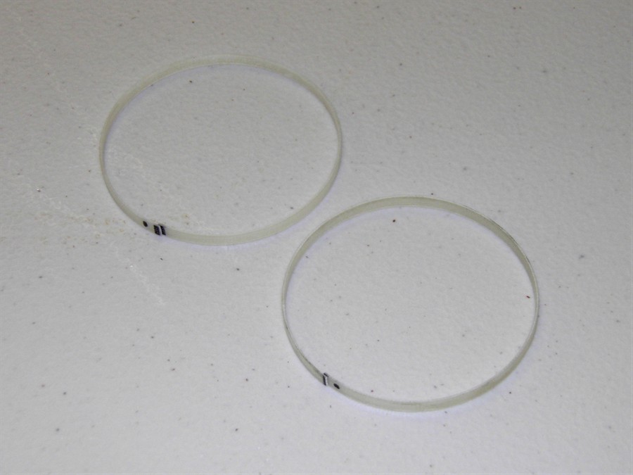
the tapered section and split, so we glued a
fiberglass ring to the top of the pressure
chamber for the payload section to sit on.
This way it could not slide any further.
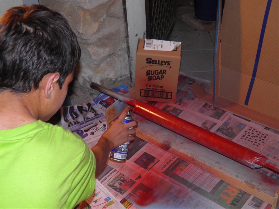
We also ended up buying red, yellow and
black spray paint along with a couple of
cans of spray putty from Supercheap Auto.
PVC pipe used to catch nozzle
slug
Launcher in place for test
Nozzle slug
Test 1 @600psi
Test 2 @ 650psi
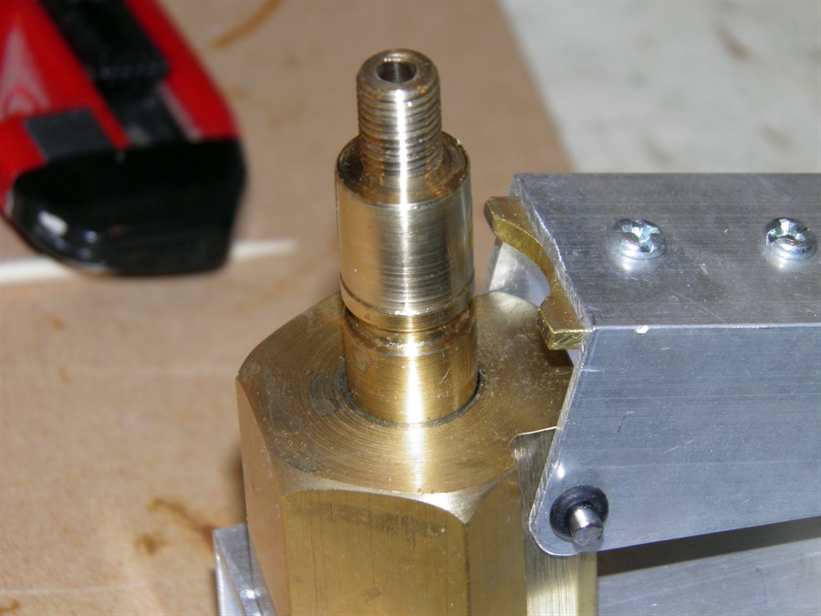
Nozzle seat with screw thread
extension
Fiberglass payload bay support
rings
15 February 2015
- We made a couple of screw switches
today out of old PCB. We are using these to
get a secure power connection during the
high G launch. They are also nice and
compact.
We filled gaps with epoxy around base of
the payload bays. We also pulled off the
shroud lines from the second parachute ready
to have the new ones sewn on.
Adding extra support for PVC
rings
16 February 2015
Today we masked off the fins and nozzle
and sanded the rockets back with 240grit
paper to get them ready for painting.
Masking fins and nozzles
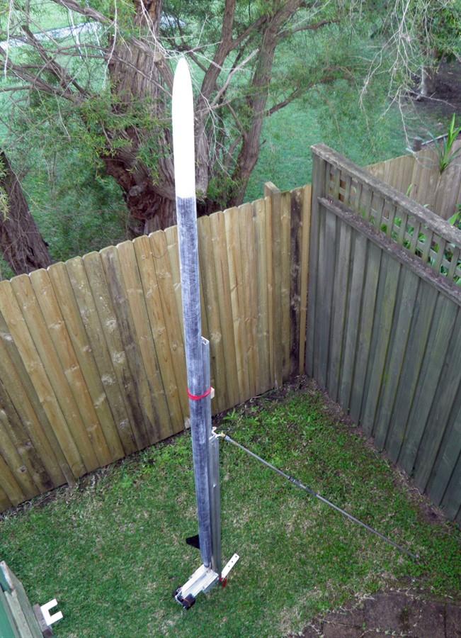
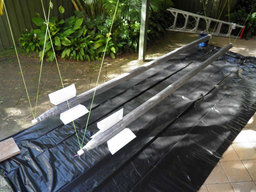
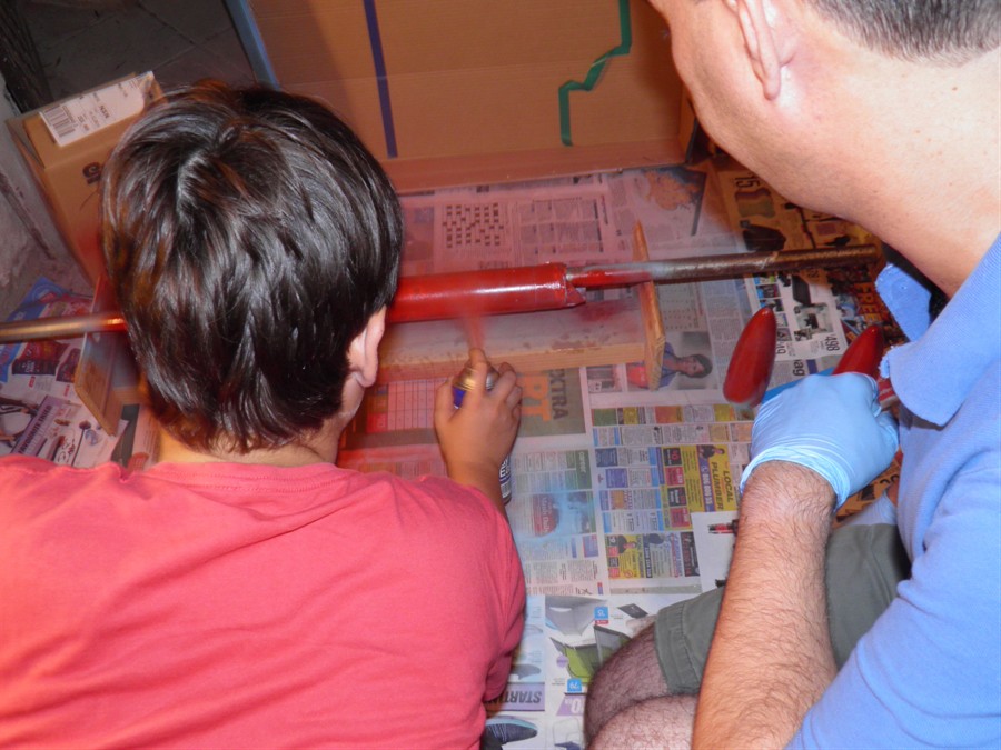
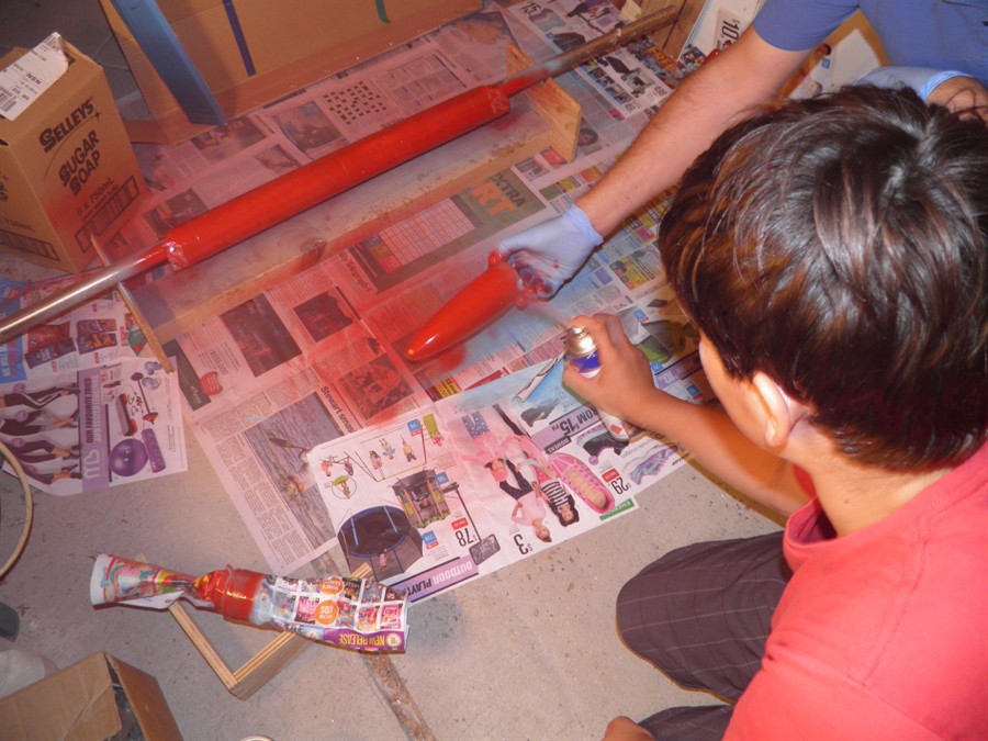
17 February 2015
-
We spray painted both #1 and #2 with
Spray putty and then let it cure after about
4 coats. Later that night we sanded it back
to almost the CF again giving a fairly
reasonable smooth finish. We also replaced
the top fiberglass hinges of the launcher
legs with brass ones as the old ones started
to crack.
Suspended ready for painting
Fins and nozzle are masked
Spray putty used for filling
gaps
Sanding back putty
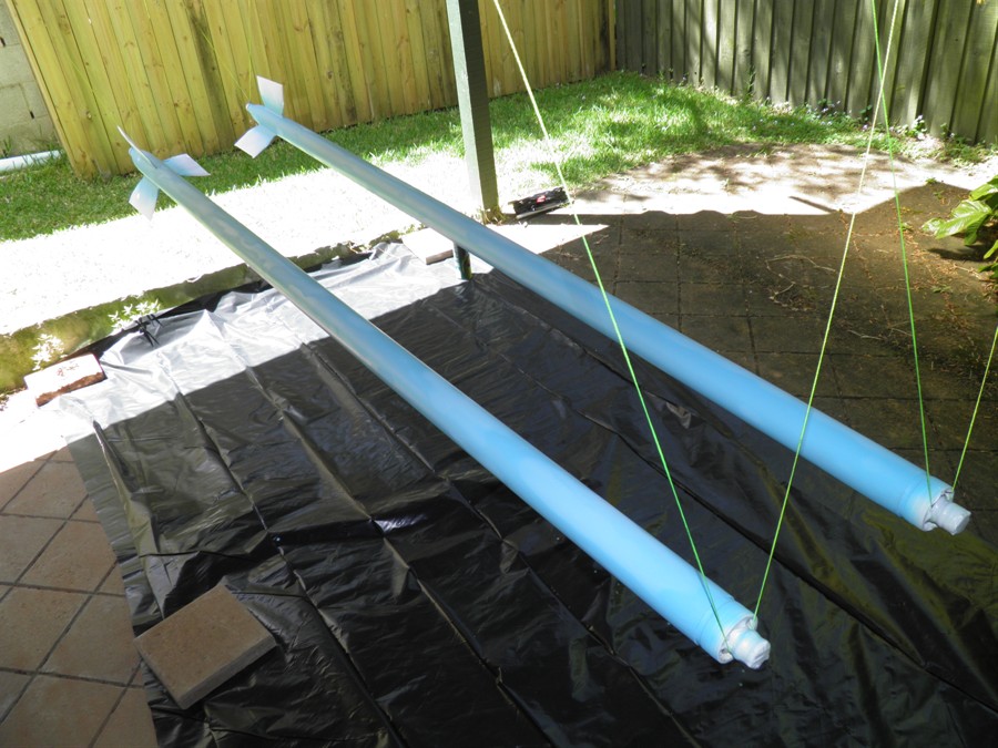
18 February 2015
- We
painted #1 and #2 with yellow spray
paint. We did 3 coats but will need to do
another 1 or 2 because a little bit of the
underlying CF is still showing through a
little. Overall the finish is quite good and
better than what was expected.
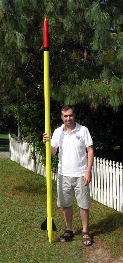
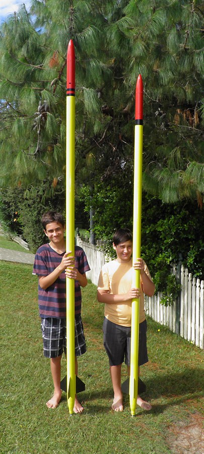
Yellow was chosen so they are
easy to see and
won't heat up too much in the
sun.
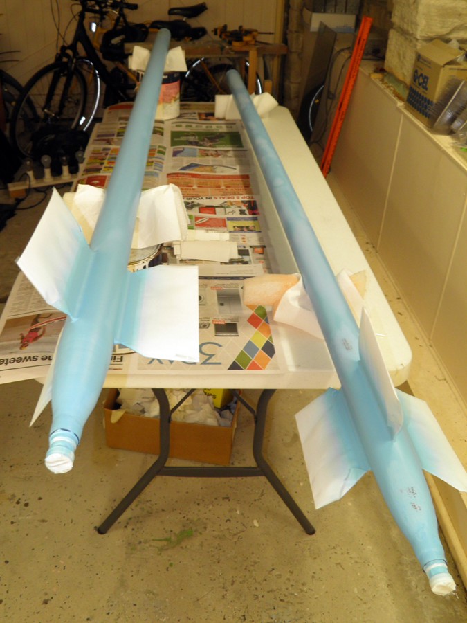
19 February 2015
We sprayed another couple of coats of
paint on #1 and #2.
20 February 2015
-
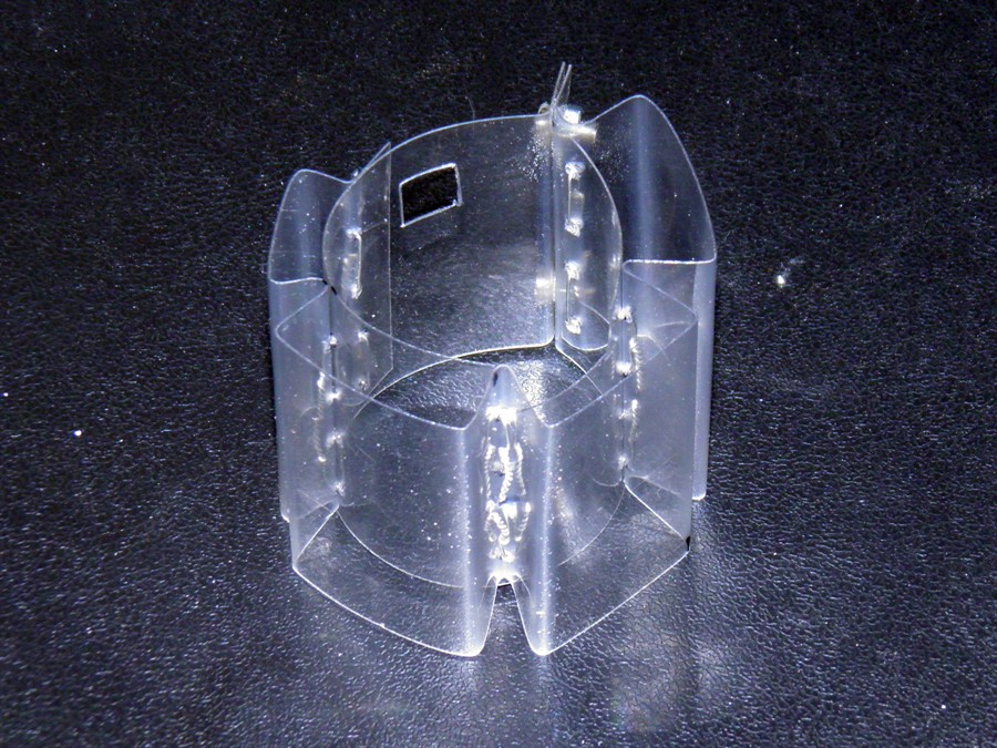
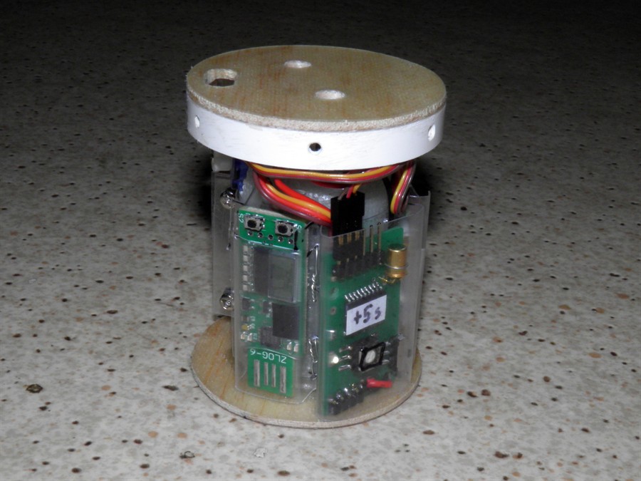
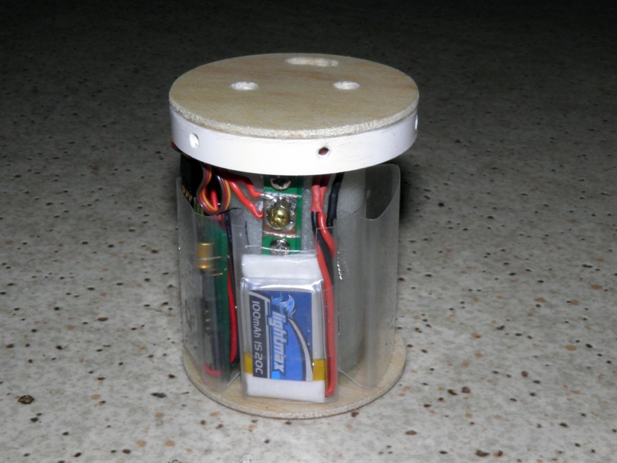
We continued to work on deployment mechanisms.
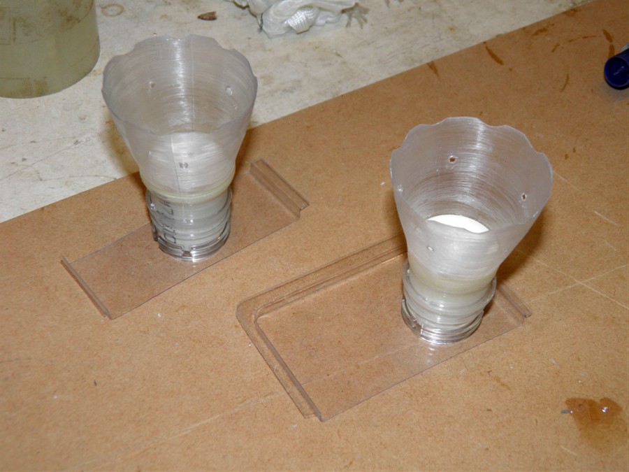
21 February 2015
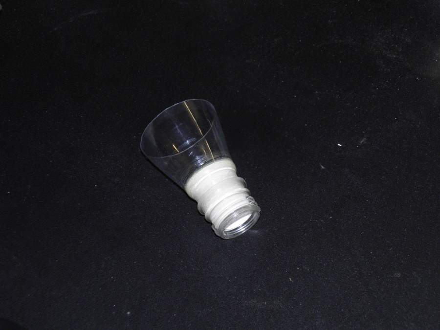
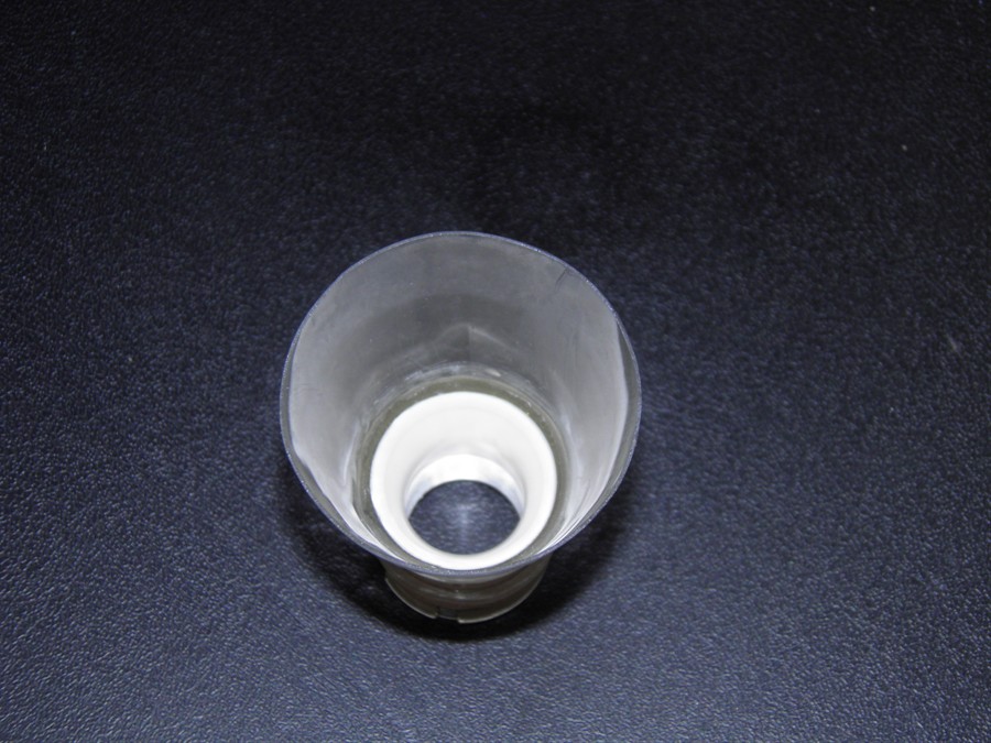
- The electronics in the payload bay are
mounted around the outside of the inner
fiberglass tube. When trying to come up with
a best way to mount the flat PCBs onto the
tube, we tried velcro, but it didn't give
enough security for the electronics in a
high G environment, and then my wife
suggested what about pockets? And so we went
with that. We made a set of pockets from PET
plastic that allows us to see any displays
with holes cut out for buttons access. The
electronics PCBs rest up against the bottom
bulkhead to withstand the acceleration
forces. The pockets allow us to remove the
electronics and place them on other rockets
as needed. There is a pocket each for: zLog
altimeter, Servo Timer II, Battery pack and,
Altimeter One. The whole set of pockets is
screwed together with a couple of screws to
hold it securely around the central tube.
The screw switch is mounted permanently to
the fiberglass tube opposite the servo
motor. We finished mounting everything for
the first rocket.
PET pockets for electroncis
Top view
The electronics fits snugly
inside
Battery pack
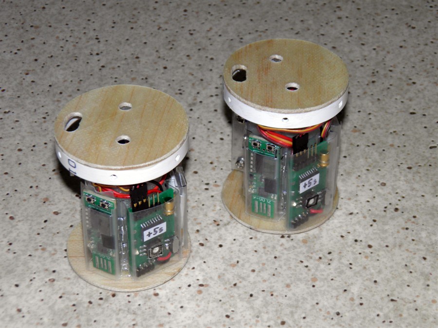
22 February 2015
- Today we made a second set of pockets
for the second rocket and mounted all the
electronics in it.
Two payload sections almost
ready to go
23 February 2015
- We are using an AltimeterOne as a
second altimeter so we can correlate the
data from the zLog. Because in it's case the
AltimeterOne is just a little too thick, we
just removed it from its case and placed the
battery next to the PCB. We mounted this
with double sided tape to a piece of PET
backing plate.
We also drilled all the access holes for
the
electronics in both payload bays. We also
mounted the cameras in the nosecones sitting
at an angle on dense foam.
24 February 2015
- We attached the wire loop to one of
the grapple arms that hooks over the servo
motor horn. We did this for both the
deployment mechanisms. For the shock cord we
are using 3mm braided nylon cord, it's the
same stuff we use on all of our rockets.
Connection is very simple we just make a
loop at one end which then pins to the top
of the pressure chamber, The other end is
threaded through the deployment mechanism,
and then threads through the nosecone.
Friction keeps the nosecone in place on the
shock cord and then finally it goes to the
parachute where we make another loop.
Lastly we used the Open Rocket simulator
to model the rocket so we could figure out
the positions of the CP in relation to CG.
We marked the CP point on the rocket as the
LCO may want to check the rocket stability.
25 February 2015
- We washed the nosecones and payload
bays with warm soapy water to try to remove
any greasy finger prints that may have made
their way onto them. After drying we then
sanded them back with 240grit paper and
spray painted them with spray putty. We'll
let them dry overnight and we can do the
first paint coat tomorrow.
Sprayed with putty and sanding
back
26 February 2015
- We sanded the putty back to the
fiberglass and sprayed the first coat of
paint.
Spray painting payload section
Lever arm length comparison
More painting
And can't forget the nosecone
27 February 2015
- We sprayed 3 more coats of paint onto
both nosecones today. I'm not liking this
paint that much as it doesn't give very good
coverage and needs multiple coats. We also
ran some simulations to see how the rocket
would likely perform.
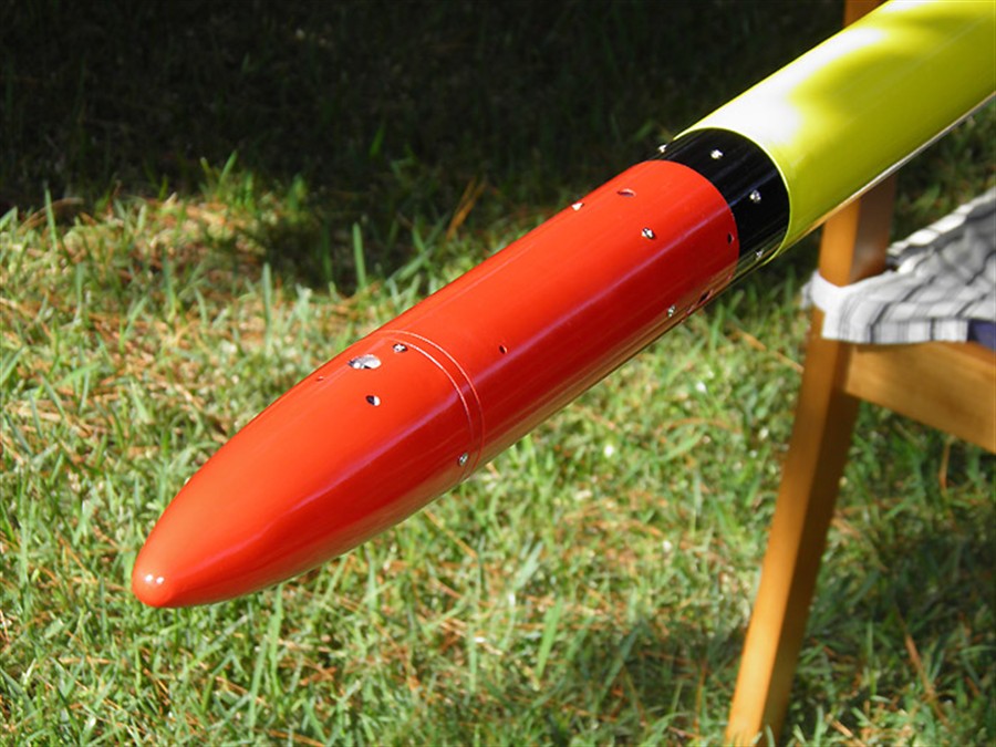
28 February 2015
- We sprayed the black bands on nosecones
today which finishes the painting for these
rockets.