Date: 24th
October 2007
Location: Workshop
Conditions:
Pleasant
Team Members at
Events:
GK, PK
Unfortunately it was too windy this
weekend to fly more altimeter
flights. Since there are no flights to
report, we thought we would do a
progress update of what we are currently
working on in the workshop.
Polaron IV
From our thrust tests earlier in the year
we noticed that the Polaron rocket produced thrust for around 7 seconds
using Jet Foaming and a 7mm
nozzle. Compare this to full bore nozzles
where the thrust lasts typically only
hundreds of milliseconds. Here is the
video of the test
(see the last test in the video). We thought this
was pretty interesting and would make for some
great footage in flight of a long
duration foam
trail.
From past experience we know that
launching even smaller rockets with a 7mm
nozzle and foam can produce
unpredictable
results(second flight) mostly due to the low initial
thrust. The resultant low take-off speed
causes the rocket to be quite unstable with
the rocket not having sufficient speed for
the fins to work properly. The slow release
of water also increases the amount of time
the center of gravity stays near the tail
end of the rocket, further compromising
stability.
Polaron III
has flown twice with foam
before using a 9mm nozzle. The first flight was
excellent, but the second leaned over too
much and for some reason the parachute did
not deploy and the rocket was completely
destroyed. Although it did not survive it
still travelled over 200 meters from the
launch pad. A 7mm nozzle has around 40% less
cross sectional area when compared to a 9mm
one.
So we decided to build Polaron IV to
explore this long duration burn. To overcome the
low thrust on take-off we are using
three booster segments that will passively
fall off when they stop producing thrust.
These will work similarly to how
Trevor's
Green Ant Shuttle rocket worked. Although the retention of the boosters will
be slightly different.
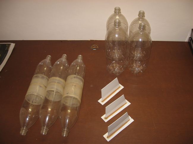
In order to keep things simple, there
will be no staging mechanism and the Polaron
rocket will also fire at lift-off. The
individual booster segments are constructed
from two 1.25L spliced bottles and use 13mm
nozzles. The segments are designed to return
to earth without a recovery system again for
simplicity. The whole rocket is being
designed so that we can extend the main
rocket as well as the boosters for increased
capacity.
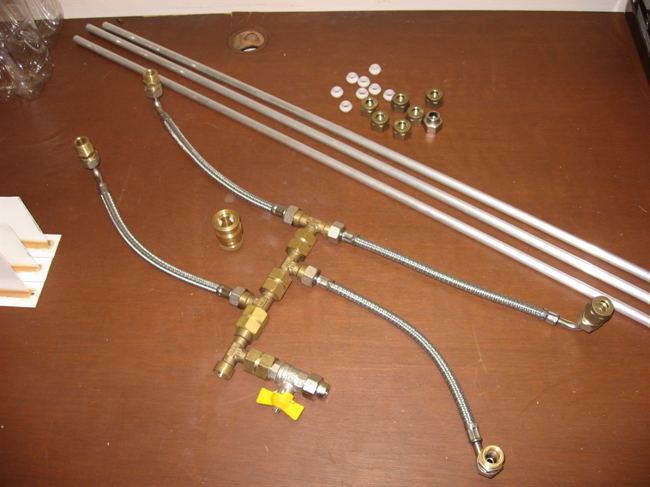
Launcher
Due to the booster configuration we have
to build a completely new launcher for this
rocket and others like it. It will be
similar in design to the Acceleron launcher
but will replace the central release
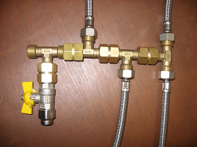
mechanism with a gardena release mechanism. The launcher uses 12mm launch
tubes only for the boosters. Most of the
plumbing is made of brass and the hoses
going to each nozzle are rubber with
external braided steel sleeve. It is rated
to at least 450psi.
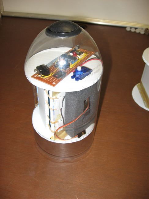
Rocket
We are currently
building the nosecone for the rocket. It is
almost identical in design to what we have
been using for the
Hyperon rockets except it
is 110mm wide. We are also building a second
one in case the first one gets damaged. It
is easier to build two at the same time then
to go back and build it later. It will also
give us the ability to switch the nosecones
in the field.
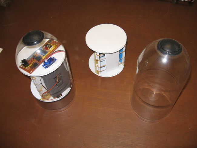
The nosecone uses V1.3.1 of the
flight computer and will be equipped with a
camera and an altimeter. A new bigger chute
will also be made, as Polaron III used a
pair of smaller ones.
We
have the boosters already glued and the
fins will be reused from the original Polaron rocket.
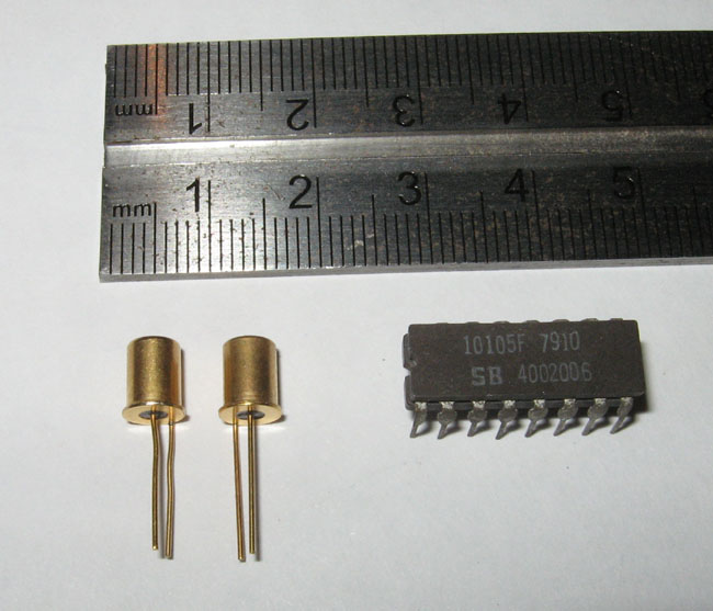
Our new acceleration switches arrived
today too from RS Electronics. (see photo on
left) These things weigh less than a gram
and are supposed to activate at around 5Gs.
We are keen to fly them and will be ideal in
reducing the footprint and weight of the
flight computer.
Hybrid Splice
On the
Yahoo water rocket forum, Pat
LeBlanc had a good suggestion for an
alternative way of joining two bottles. The
hybrid splice attempts to overcome the
limitations of regular glue-only splices
which require special glues such as PL
premium to provide enough strength to hold
bottles together under pressure. It also
attempts to overcome the limitations of
Robinson couplings that typically have a
small hole for air/water to pass through
leading to efficiency losses.
The idea was that you could have a
full bore coupling between bottles without
the need to seal the coupling where it
passes through the bottle. Instead, another
sleeve between the two bottles provides the
pressure seal. The hybrid splice also allows pressure to
exist on both sides of the coupling, meaning
that distortion of the lobes of the bottles
would be virtually eliminated. After a
number of discussions with forum members we
had a go at constructing and testing a
hybrid splice.
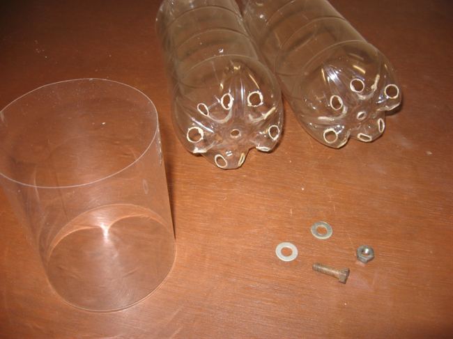
Our first idea for the hybrid splice
involved using 5 screws in the lobes of the
bottles holding the bottles together, with
just a big hole in the middle to let the air
pass, but finally chose an alternate design
that would make things a little easier to
construct. We replaced the Robinson coupling
in Pat's idea with just a simple bolt in the
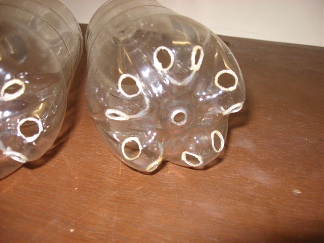
middle. We then made 10 holes in the base of
each bottle ( 2 in the side of each lobe )
with a heated 10mm rod. The air
holes were aligned with the corresponding
ones in each bottle so that the air could
flow easier from one bottle to the next. The
hole for a bolt was just drilled in the
middle. We
used a metal bolt for the test, however, a
nylon one should be used for safety and
weight reduction reasons.
To tighten the bolt we just used a
socket wrench with an extension and a long
screwdriver. No other special tools were
needed.
The total cross-sectional area of all the
holes was equivalent to a 32mm Robinson coupling.
That is about 15 times bigger than our
typical 8mm coupling.
The idea behind this hybrid splice was
that no special components such as threaded
lamp rods or tools were needed. The other
idea is that
even an inexpensive glue could be used to
provide the seal in the sleeve since the
bolt in the middle would be providing the
holding force.
Test Results
We spliced two 1.25L bottles and let it dry for about 4
days and then performed a hydrostatic burst
test on it. The splice held up to 130 psi. The sleeve was held
down by a combination of PL Premium and VISE
glues. After we put the PL glue in we
noticed there were a couple of minor leaks,
so we poured the runny VISE glue in to fill
those, and that sealed it well. 130psi is
not all that great for this particular
hybrid design when you
consider the VISE glue-only splice held
170psi+ and our Robinson couplings hold also
around 170psi+ with bottle burst pressures
around 190 psi. A 130psi splice means about
100psi operational pressure.
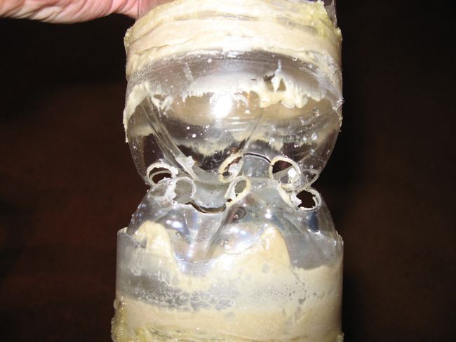
It is unclear what the initial failure
point was but both bottles cracked between
the holes in the bases and the sleeve also
ripped all the way around. It did not
delaminate from the glue, the plastic
failed. After a number of discussions with
forum members we now suspect the failure was
at the sleeve first and when that failed the
bottles did. Normally a sleeve like that
should hold at least 180-190psi. The bottles
still remained together and no shrapnel went
flying. It looks like the holes in the sides
have weakened the bases too much.
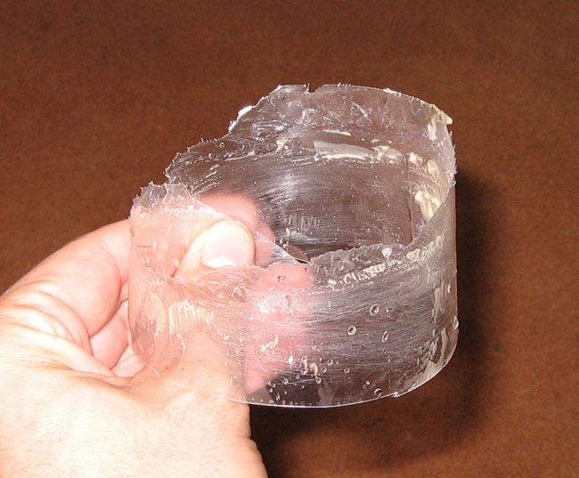
It was a really unusual failure because
the sleeve edges are still attached to the
bottles all the way around. The straight
edge seen on the torn sleeve photos is from
the scissors when I cut the sleeve away to
photograph the inside.
Conclusions
If the sleeve failed first that means
that the bolt wasn't doing a good job of
holding the bottles together. When we first
bolted the bottles together we noticed that
there was a certain amount of give. The
bottom of the bottles flexed a little when you
pulled on the two ends. This was seen before
gluing the sleeve on. With the one bolt,
this flex in both bases was probably enough
to put most of the strain on the sleeve when
pressurised. Because the pressure was the
same on both sides of the lobes you didn't
get the typical crack propagating from the
central bolt hole but rather the
circumferential cracks between the weakest
points.
The reason the sleeve may have failed at
a lower pressure is that because the sleeve
is only really held down by the ends. The
middle could have bulged out under pressure,
and placed uneven strain on it. With a
normal splice the sleeve is completely held
down along its full length by glue and so
this bulging is unlikely to happen.
The cross-sectional area of the bottles
is 63.6 cm2 and at 130 psi you
end up with a force of 581Kg! pulling one
bottle in one direction and the same in the
other direction. No wonder you get a bit of
flex in the base of the bottle.
As a result it may be better to try the
Robinson coupling Pat suggested in the first
place for the hybrid splice. Although the
coupling may experience the same flex at the
base of the bottle, putting the strain on
the sleeve again. It may achieve better
results since the bottles are not weakened
by the holes in the lobes.
Richard Wayman from
TOR water rockets is also having a go at
building a
hybrid splice that uses nylon
bolts in the lobes of the bottles, with a
hole in the middle. His bottles have a much
nicer shape for this, and we're looking
forward to his test results.
Miscellaneous
In the background we are also working on
an T-8 FTC rocket to see how they perform
first hand. The rocket will also carry a
flight computer for deployment and an
altimeter, but will not be designed to carry
a camera.
We have almost finished constructing
a new stager concept. While theoretically it
should work, we have no idea how well or if
it will work at all in real life. We will
publish full details again when it has been
test flown. |