Date: 6th January 2008
Location: Workshop
Conditions:
Indoors
Team Members at
Event:
GK and PKThis week I
thought I'd share one of the things we have
been working on in the background - the
Katz Stager. It's a staging mechanism
based on a different principle to friction
types such as a crushing sleeve, or the
locking types such as a Gardena mechanism.
Katz Stager
The key to this system is trapping
atmospheric pressure in a part of the mechanism
to ensure that there is no net force acting on the mechanism to separate the
stages. A spring is used to separate the
stages after burnout.
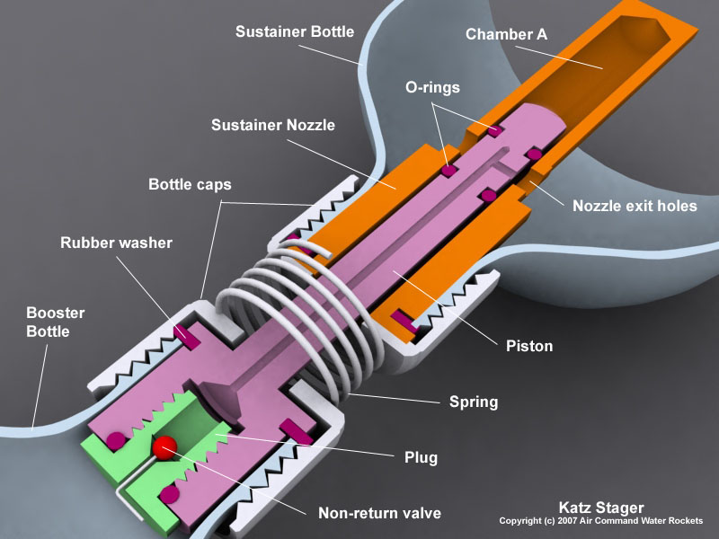
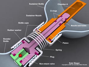
Main Components
The staging mechanism consists of the
following components:
(Click on images to see more detail)
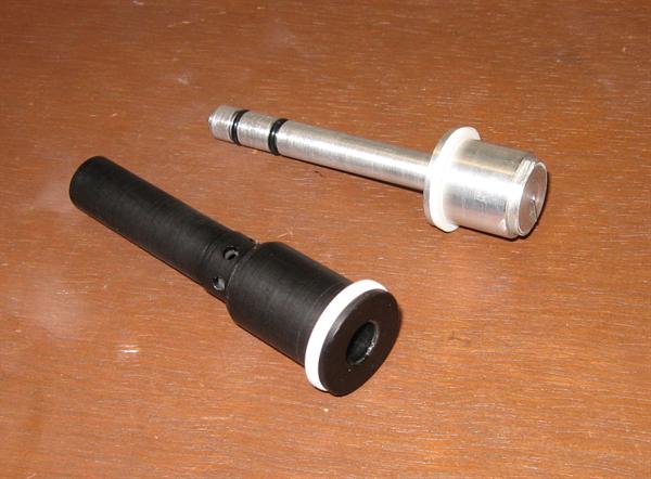
- Piston - The main component
in the booster providing the air supply
to the sustainer.
- Sustainer Nozzle - The main
component in the sustainer, traps
atmospheric pressure and acts as a
nozzle.
- Plug with non-return valve -
screwed into the base of the Piston. It
prevents air and water from coming back into
the booster.
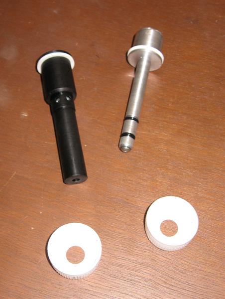
- Caps - Regular bottle caps
used to hold the nozzle and piston in
place.
- Spring - Used to provide the
separation force between the sustainer
and booster just after burnout.
How It Works
1. The sustainer is partially filled with
water and the nozzle is screwed on.
Note: Water has been omitted from the
diagrams for clarity. (It also made it
easier to make the diagrams)
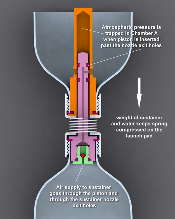
2. The booster is filled with water and the
piston is screwed on. The booster and
sustainer are turned upside down and fitted
together. This is so that water does not
enter chamber A in the sustainer. (A little
bit of water is okay). When the top o-ring
of the piston moves past the nozzle exit
holes, atmospheric pressure is trapped in
chamber A.

3. When the combination is turned back
upright, the weight of the water and the
sustainer keeps the spring compressed and
prevents the spring from pushing the booster
and sustainer apart.
4. The piston o-rings prevent water/air from
leaking into chamber A and also out past the
piston.
5. The piston has a small hole that emerges
from between these o-rings and lines up with
one of the nozzle exit holes. This small
hole continues through the center of the
piston to the plug that contains a
non-return valve made from a bent pin, much
like you might find in a crushing sleeve
mechanism.
6. When the booster is pressurized, the
higher pressure in the booster opens the non-return valve
and air is allowed to flow into the
sustainer through the piston.
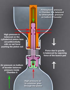
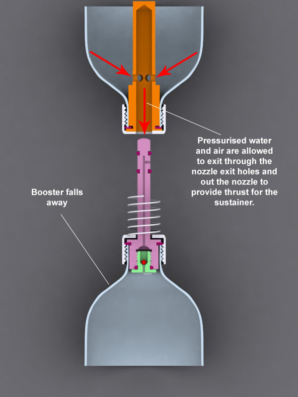
7. Now as the pressure grows inside the
sustainer, the forces on the piston are only
circumferential and cancel each other out (Red
arrows at top). There is no net force on the
piston pushing it out of the sustainer.
This is because the only area of the
piston that can exert a force to push it
out is the top of the piston and that
remains at atmospheric pressure. This is
the key to the Katz stager. This means
that pressure inside the sustainer can
be very large, yet the piston can remain
free moving as long as the pressure in
chamber A remains at atmospheric levels.
There is no need for friction or locking
mechanism to keep the sustainer from
flying off.
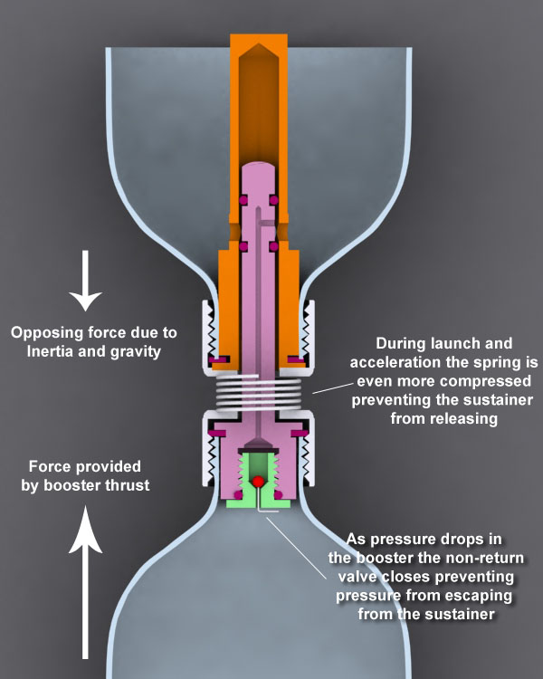
8. During launch the inertia of the
sustainer, working against the thrust of the
booster, keeps the spring even more
compressed preventing the mechanism from
staging.
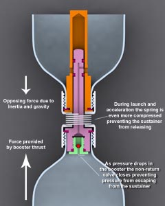
9. As the pressure drops inside the booster
the non-return valve in the piston keeps the
pressure from escaping from the sustainer.
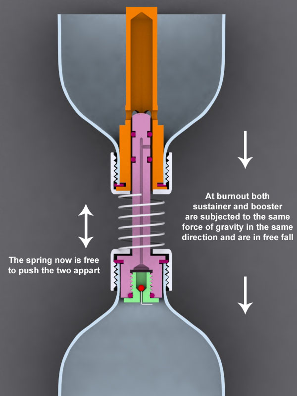
10. As the thrust from the booster drops to
zero, the sustainer and booster are
essentially in free fall and the booster is no
longer providing an opposing force to the
sustainer. (As
the ground was providing while still on the
launcher, and the thrust was providing
during the boost phase) The spring is
then free to start forcing the booster
and sustainer apart.

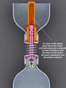
11. As the piston starts to move out of the
nozzle and the top o-ring moves past the
nozzle exit holes, the sustainer pressure
enters chamber A and now acts in full force
on top of the piston and forces it out of
the nozzle. Similar to the way a launch tube
works.
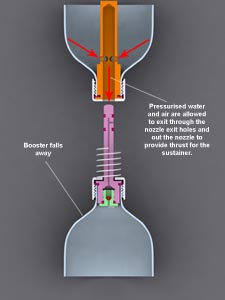
12. When the piston is forced completely out
of the nozzle staging has occurred and the
sustainer can go about its business. The
combined cross-sectional area of the nozzle
exit holes is much larger than the nozzle
cross sectional area so there is minimal
restriction of flow of water and air. (In
real life the nozzle exit holes are a lot
lower than in the diagram so water does not
collect around the base of the nozzle.)
You are probably asking yourself why such
a complex mechanism is needed, when a
crushing sleeve is so much simpler? We
wanted to bring another design idea to the table
that may help spark other ideas based on
this concept. Here are some advantages and
disadvantages.
Advantages
- The sustainer pressure can be very
large.
- Other than the spring there are no
moving parts.
- Relatively lightweight and compact design.
- A long thin nozzle is not necessary as
with a crushing sleeve.
- The nozzle diameter can be quite
large. Perhaps as much as 20mm. Large
diameter crushing sleeve mechanisms are
difficult to build.
- There is potential to use a De Laval
nozzle with this design.
Disadvantages
- Components need to be fabricated -
cannot be made from household items.
- The spring tension needs to be
chosen appropriately for the sustainer.
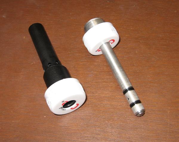
Current Status
We have built a prototype
of the nozzle and piston and have fired it 3
times horizontally with air only. This was
to test to see if Chamber A would retain the
atmospheric pressure. We used our hand to
push the sustainer and booster apart in the
tests. The piston was a little more stiff to
push out than what we would have liked, but
softer o-rings and a little more silicon
grease should help that out.
What's Next ?
We need to find the right spring with
the correct force to separate the two and then
test fly the mechanism.
Concept Extensions
This mechanism could equally be used as a
launch mechanism on a launcher. The rocket
could be pressurized to high pressure
without the need for a strong retaining
mechanism. A small lever would replace the
spring and would serve to push the two
apart in order to launch the rocket.
With the described mechanism, you could
not use a launch tube, however, the design
could be easily modified to place the
chamber at the top of the rocket (such as in
the neck of the upper bottle) and the launch
tube would work as the piston, trapping the
atmospheric pressure in the neck of the top
most bottle.
|