Each flight log entry usually
represents a launch or test day, and describes the
events that took place.
Click on an image to view a larger image, and
click the
browser's BACK button to return back to the
page.
Day 84 - Acceleron V - Pressure switch
PS3 pressure switch prototype.
Cover removed
Water is poured into the booster segment and
the pressure switch is screwed on top and then
connected to the flight computer.
Here you can see the rubber membrane.
PS3 undergoing a hydro test.
Setup for testing the switch activation
timing on the thrust stand.
The top of the booster segment is attached
to the thrust test stand using half a bottle.
Date:23rd
December 2009
Location:Workshop
Conditions:Pleasant and warm
Team Members at Event: PK and GK.
Pressure Switch
We have been developing a new pressure
switch for the Acceleron V rocket as the
previous ones have been either too leaky or
not reliable enough. The latest iteration is
the PS3.
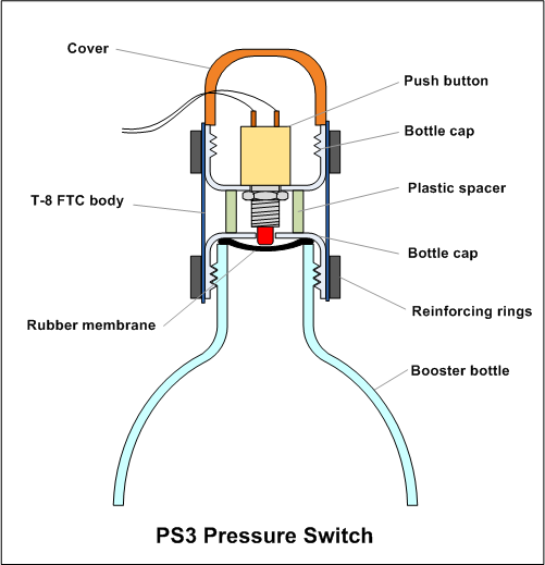
The switch is based on a regular push
button switch mounted behind a rubber
membrane. The pressure switch is simply screwed to
the top of the booster. The diagram below
details it's construction. The lower bottle
cap contains the rubber membrane and has a
small hole for the switch arm to pass through.
The switch body is mounted in another cap which
is held in place by a piece of T8 FTC. Two
plastic reinforcing rings were added to the
outside of caps to help secure the T8. Only
the bottom cap is glued to the FTC. The
upper cap is held down by two screws to
allow the switch to be removed for servicing
if needed. There is a small plastic spacer
between the two caps to keep the right
distance.
The particular switch we used was an old
one we had on hand, but it was chosen
because of the force needed to make
contact. The spring in it is strong enough
to deform the membrane back into the bottle
when the pressure drops. One of the problems
with a previous pressure switch was that the
spring in the micro-switch just wasn't
strong enough.
A cover made from a kinder surprise egg
prevents moisture entering the switch when
the second stage is released.
Testing
Activation pressure
The first tests we put the switch to was
to see what it's activation pressure is. A
low activation pressure means you could get
a slow response and potentially false
triggers, and a high activation pressure
means that it triggers too early before burn
out. We were aiming for a 20-30psi range.
The activation pressure we saw on the first
tests was 30psi which was at the upper end
of the desired range.
When hydro testing the switch to 130psi,
we noticed that the activation pressure was
closer to 40psi which was a little high. But
this may have been skewed by the fact that
we were reading the pressure at the tank
end, and since the hose has little holes it
means that it takes a while for the
pressures to equalize at the bottle end.
Since we were going all the way up to
130psi, we didn't bother to wait for the
pressure to equalize at the lower pressures.
( During later static tests the activation
pressure was closer to the 20-25psi mark)
Activation Timing
The main test we wanted to do was to see when it activates in
relation to the trust produced by the
booster. During Acceleron V's last flight it
looked like the old pressure switch
activated really late. It was well
after the back up system fired. We
wanted to see if the new pressure switch would also
activate in a similar manner.
For this experiment we made a booster
segment out of two of the new spliced-pairs
and fitted the pressure switch on top. Since
the switch was now sitting on top of the
booster we could not directly connect it to
the test stand. So we attached half a bottle to
to the top of the booster covering the
pressure switch and giving us a way to
attach the booster segment to the load cell. A small
battery and LED were connected to the switch
so that we could see when it turned on.
We recorded the thrust curve on the
laptop and video-taped the LED with both
high-speed and regular video. In a video
editing suite we measured the time it took
for the LED to turn off after firing the
rocket. In hindsight I should have connected
the pressure switch to a second channel on
the data acquisition unit. We then compared
this time against the thrust curve to see
when the switch was activating.
I had to turn down the gain on the load
cell amplifier, because with the 15mm nozzle
simulation predicted the booster segment
would generate about 270N thrust on
release. (The load cell can go up to ~700N) We did
5 tests all up to measure the timing.
The capacity of the booster segment was
~6.3L. Each test used 2L of water.
Test
Pressure (psi)
Nozzle (mm)
Time to
Activation (sec)
1
125
15
0.08*
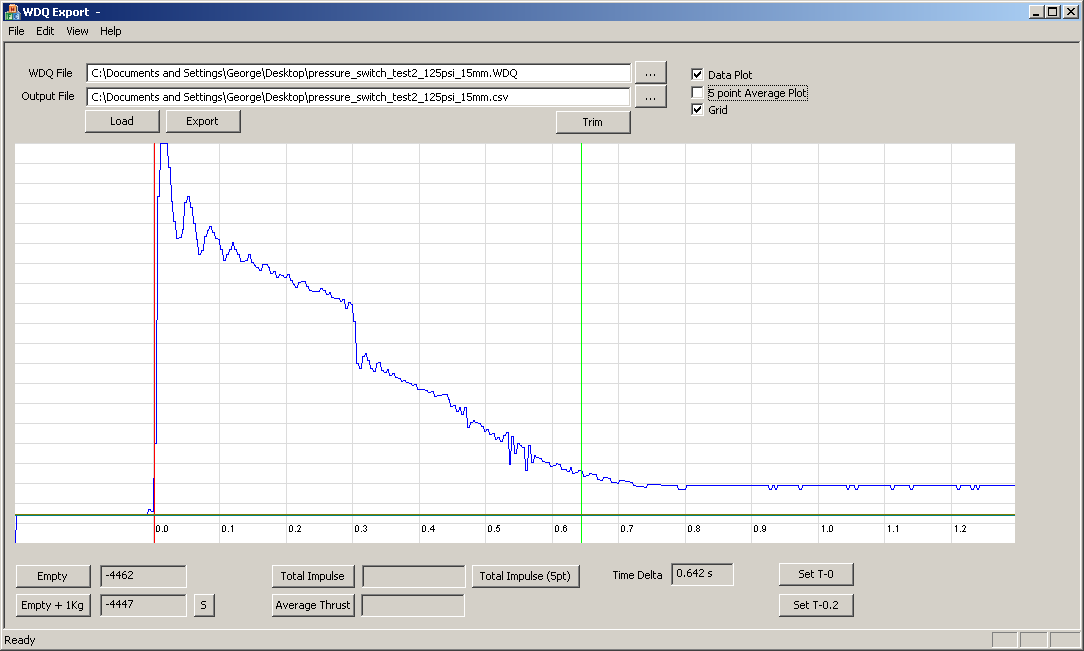
2
125
15
0.64
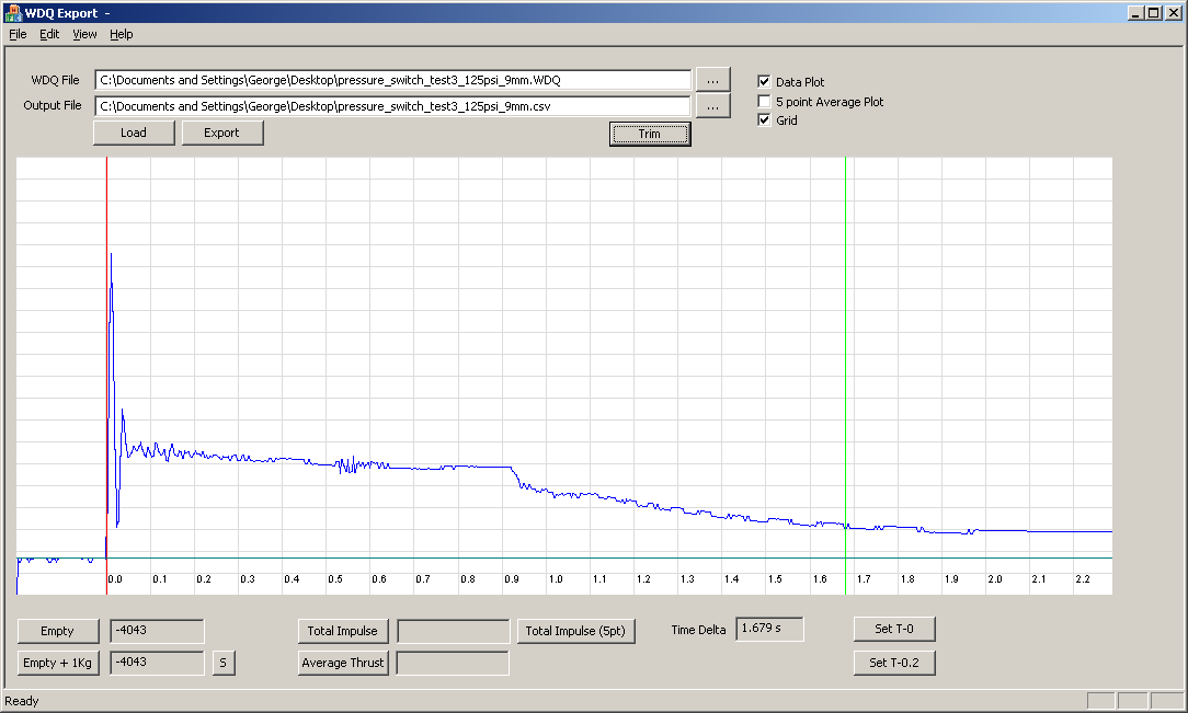
3
125
9
1.68
4
120
15
0.68
5
120
15
0.72
Timing Test Results
Notes
We chose to use slightly lower
pressures in these tests in order to
reduce the stress on the bottles since
these are flight hardware.
The 9mm nozzle test was used to
stretch out the thrust curve so we could
see the timing more clearly.
Thrust was only measured on tests
1,2 and 3. Timing was measured on all 5
tests.
*The first test showed the LED
turning off as soon as the rocket was
launched, but the mounting bottle had
also buckled which may have caused a
false reading.
Tests 2-5 showed quite consistent
readings.
Thrust curve and switch
activation timing for Test #2.
Thrust curve and switch
activation timing for Test #3.
Here is a short video of the tests.
Conclusions
The switch seems to be performing quite
well and is holding up to the pressure. The
timing is also good as it activates just
prior to the end of thrust which allows us
to set a staging delay via the flight
computer. This delay will also
depend on other tests such as how long it
takes for the
staging servo to release the second stage.
When we attached
the pressure switch during one of the tests, the rubber membrane did
not seat properly and we had a small leak. The
main problem is the switch is distorting the
membrane. The solution on launch day will be
to first mount the rubber membrane and cap
and then secure the switch body into it.
Other than the buckling support bottle,
we also managed to damage the release head
on the end of the hose as it smacked against
the concrete tiles on launch. We have a
safety line that normally prevents that from
happening, but this time the higher force
managed to stretch the string more than
normal and the head made contact. We did a
temporary fix to finish the tests, but it
will need to be replaced.