 |
 |
![]()
![]()
![]()
|
|
last updated: 3rd May 2026 - Day 245 - Launch Tubes #3 |
|
|
|
Splicing Bottles AS#5 |
|
#235 - Coming Soon |
|
#234 - Coming Soon |
|
#233 - Coming Soon |
|
#232 - Coming Soon |
|
#196 - Coming Soon |
|
#193 - Coming Soon |
|
#172 - Coming Soon |
|
|
| FLIGHT LOG | |||||||||||||||||||||||||||||||||||||||||||||||||||||||||||||||||||||||||||||||||||||||||||||||||||||||||||||||||||||||||||||||||||||||||||
|---|---|---|---|---|---|---|---|---|---|---|---|---|---|---|---|---|---|---|---|---|---|---|---|---|---|---|---|---|---|---|---|---|---|---|---|---|---|---|---|---|---|---|---|---|---|---|---|---|---|---|---|---|---|---|---|---|---|---|---|---|---|---|---|---|---|---|---|---|---|---|---|---|---|---|---|---|---|---|---|---|---|---|---|---|---|---|---|---|---|---|---|---|---|---|---|---|---|---|---|---|---|---|---|---|---|---|---|---|---|---|---|---|---|---|---|---|---|---|---|---|---|---|---|---|---|---|---|---|---|---|---|---|---|---|---|---|---|---|---|
|
|||||||||||||||||||||||||||||||||||||||||||||||||||||||||||||||||||||||||||||||||||||||||||||||||||||||||||||||||||||||||||||||||||||||||||
| Day 140 - Dual Thrust 2 - Improvements and Measurement | |||||||||||||||||||||||||||||||||||||||||||||||||||||||||||||||||||||||||||||||||||||||||||||||||||||||||||||||||||||||||||||||||||||||||||
|
Date: 23rd
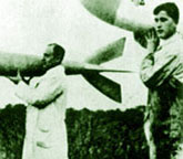
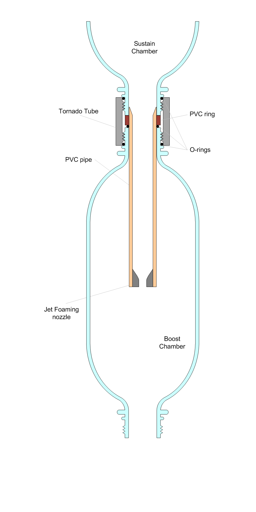
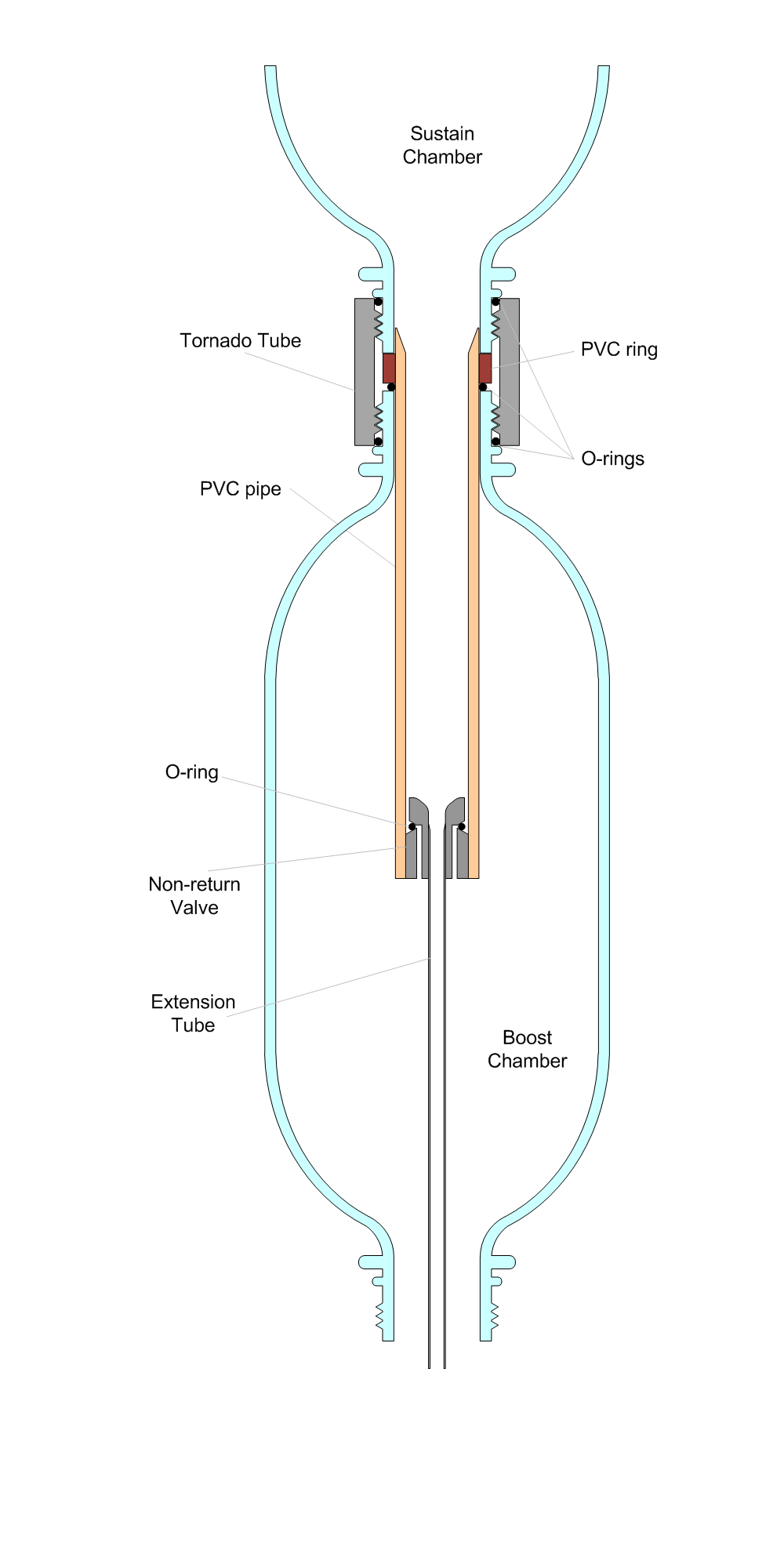
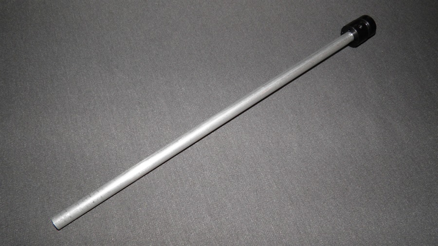
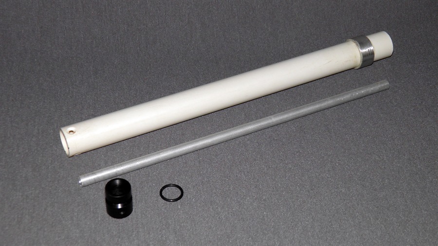
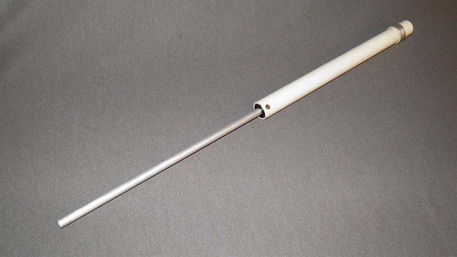
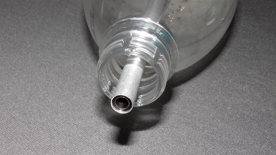
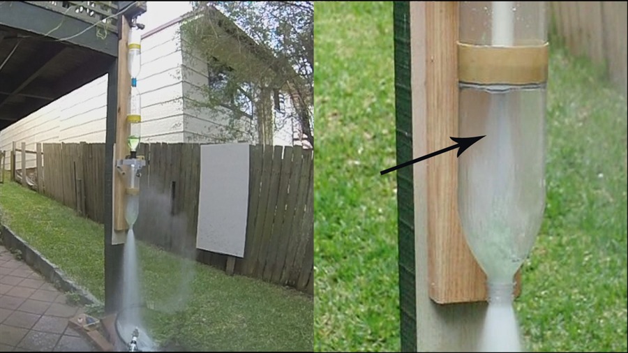
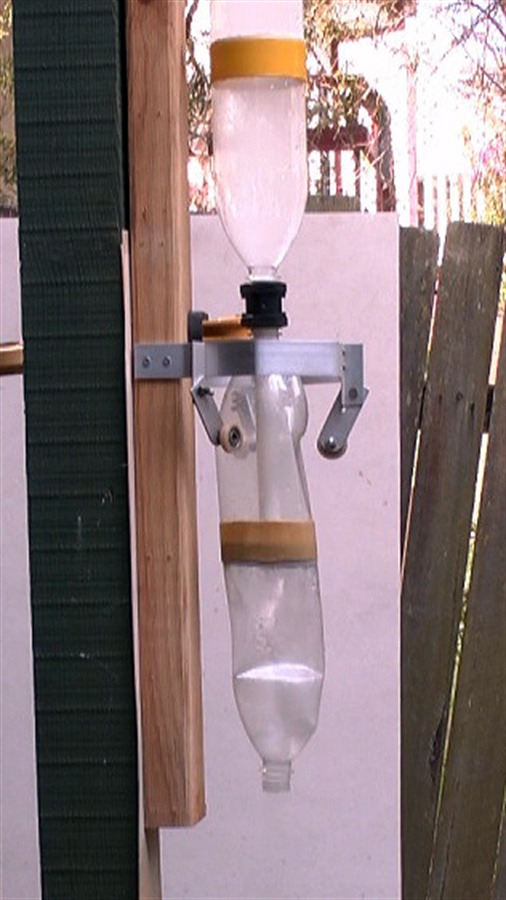
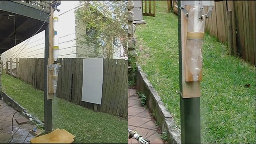
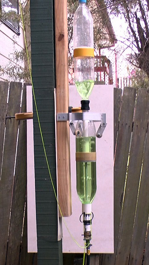
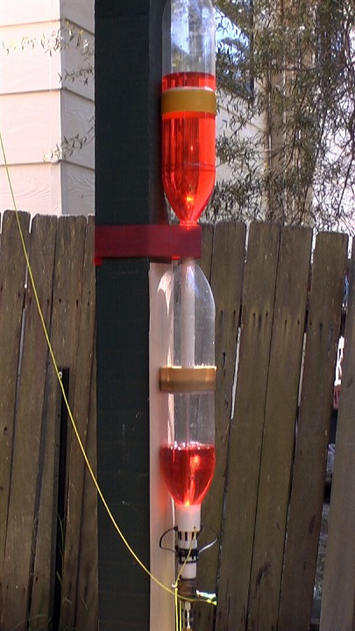
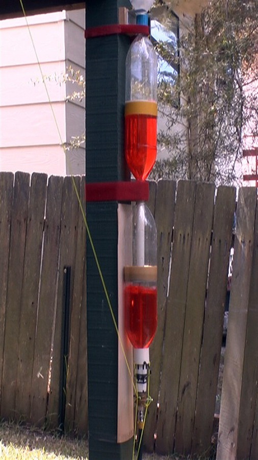
December 2013 Location: Workshop, NSW, Australia Conditions: temp 25C Team Members at Event: PK and GK. After the static tests and flight trials of the dual thrust rocket on day 138, we believed there was some room for improvement with the performance. One of the major problems was the blow-through effect allowing pressurised air to escape from the boost chamber before all the water had run out. (Here is an example of the loss of thrust due to blow-through from previous experiments.) The sustain air pulse thrust also didn't look like it was efficient due to the internal nozzle being so far into the boost chamber. Kind of like blowing into your own sail. Some water was being held up against the sides during the sustain air pulse as well. Another problem was the vacuum created in the boost chamber during the sustain air pulse causing the bottle to collapse inward. To address these issues we extended a narrow thin-walled tube down through the boost nozzle. This tube weighs 9 grams.
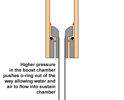
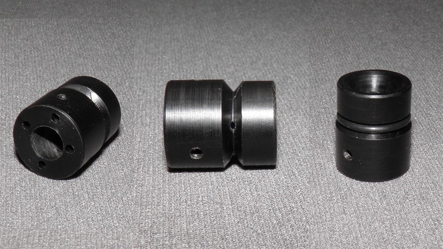
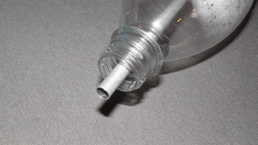
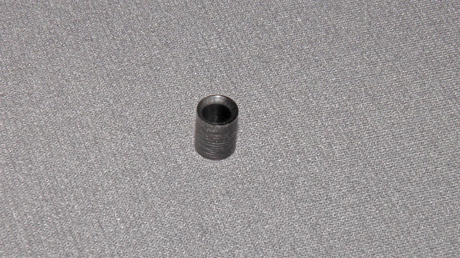
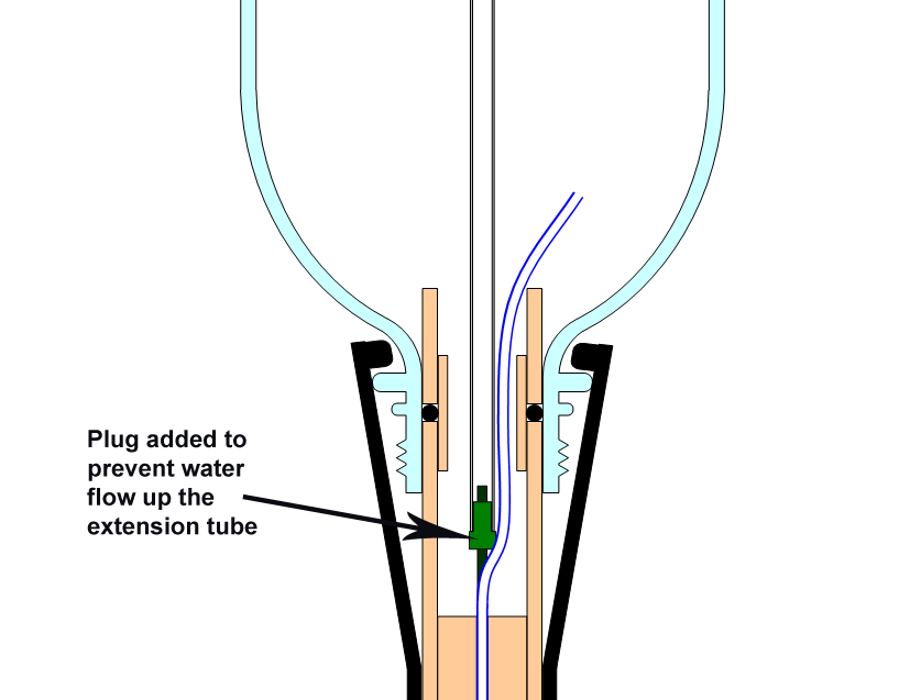
Non-return valveExtending the tube all the way down to the nozzle meant that we would lose the water self-levelling feature of the jet foaming spacer. So we built a non-return valve into the bottom of the spacer so that water and air could flow up into the sustain chamber during pressurisation. How it worksThe non-return valve is built into the adaptor that holds the extension tube inside the spacer. We cut a "V" shaped groove around the outside of the adaptor to house an o-ring. Small inlet holes were drilled from the bottom into the base of the V-groove.
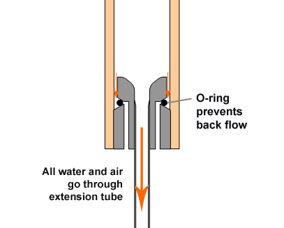
During pressurisation the higher pressure in the boost chamber causes flow through the inlet holes and because the o-ring is in a V-groove it pushes the o-ring out of the way breaking any seal allowing the air and water to flow out from under the o-ring. The top of the adaptor is narrower than the spacer with less than 1mm gap all around. This allows the water and air to flow upwards into the spacer without affecting the flow efficiency back down the extension tube during the sustain phase. Shortly after launch, the pressure differential between the sustain and boost chambers switches and the water pushes the o-ring back into the V-groove blocking the inlet holes. This ensures that all the flow from the sustain chamber only goes through the extension tube.
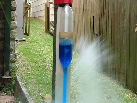
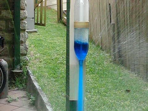
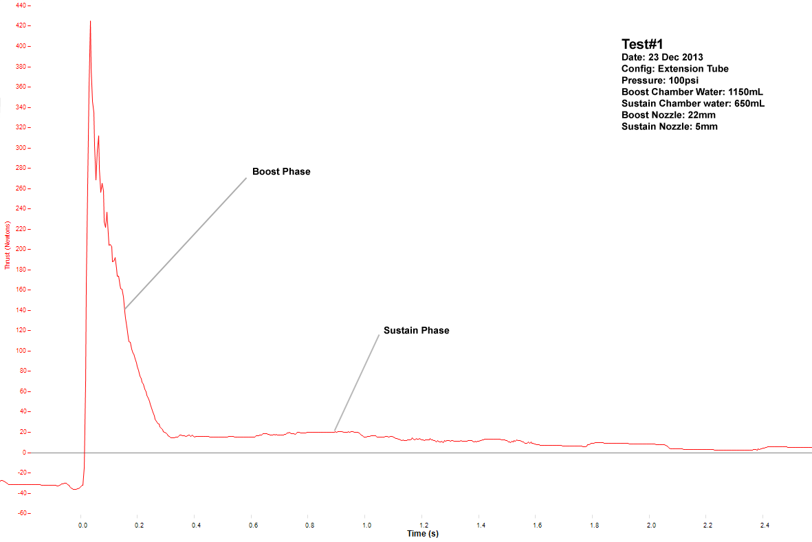
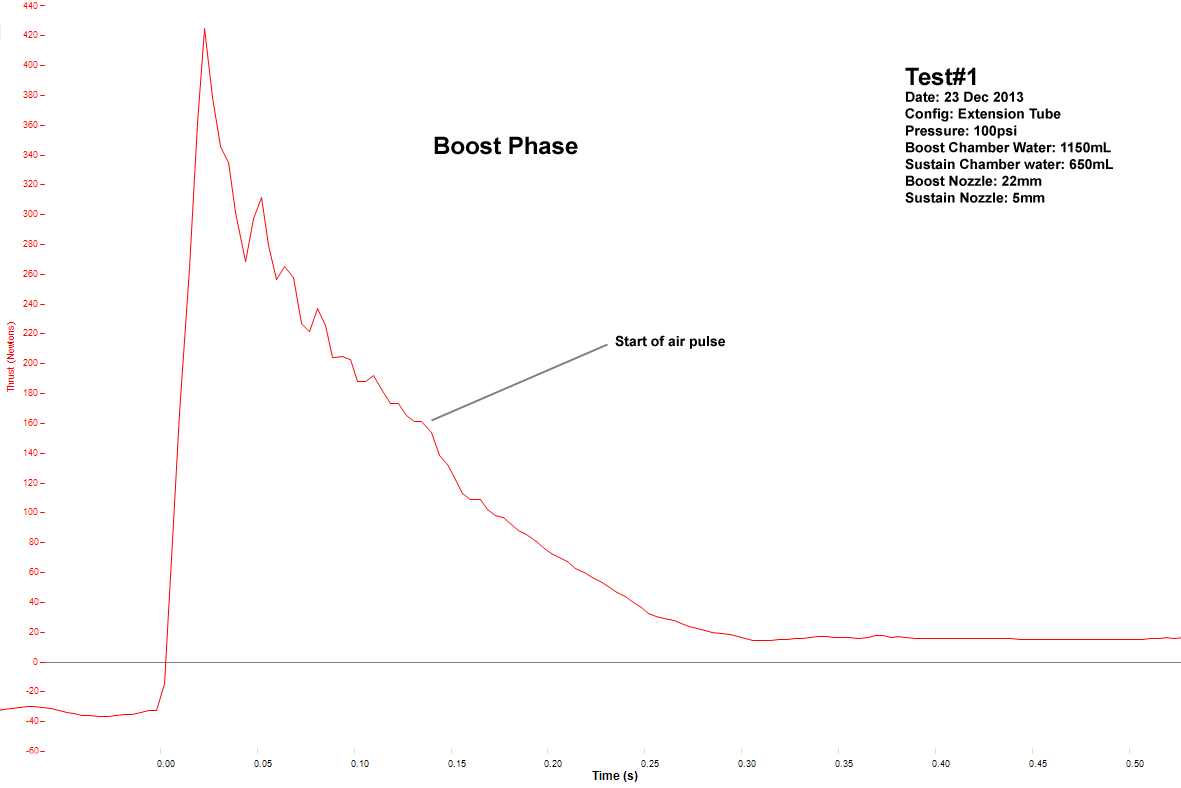
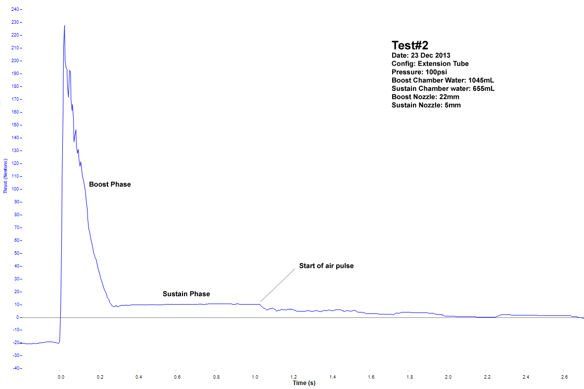
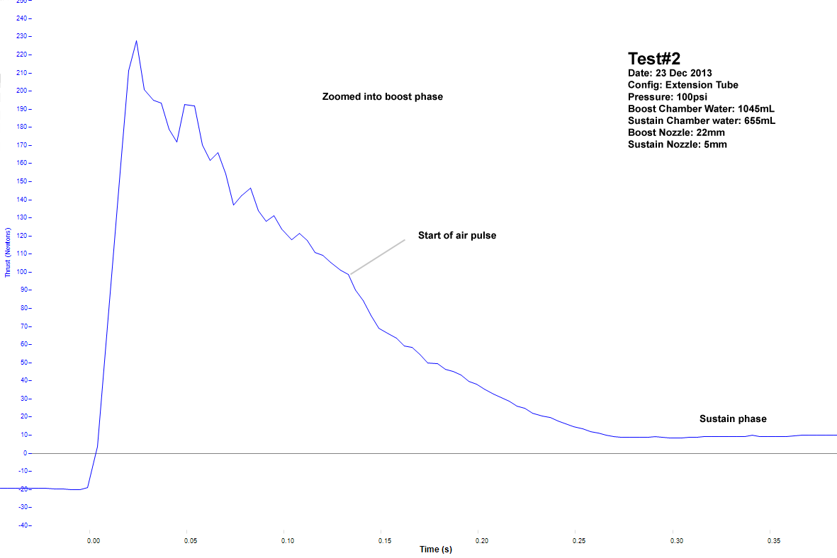
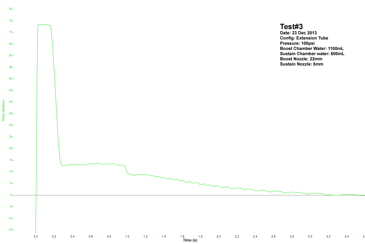
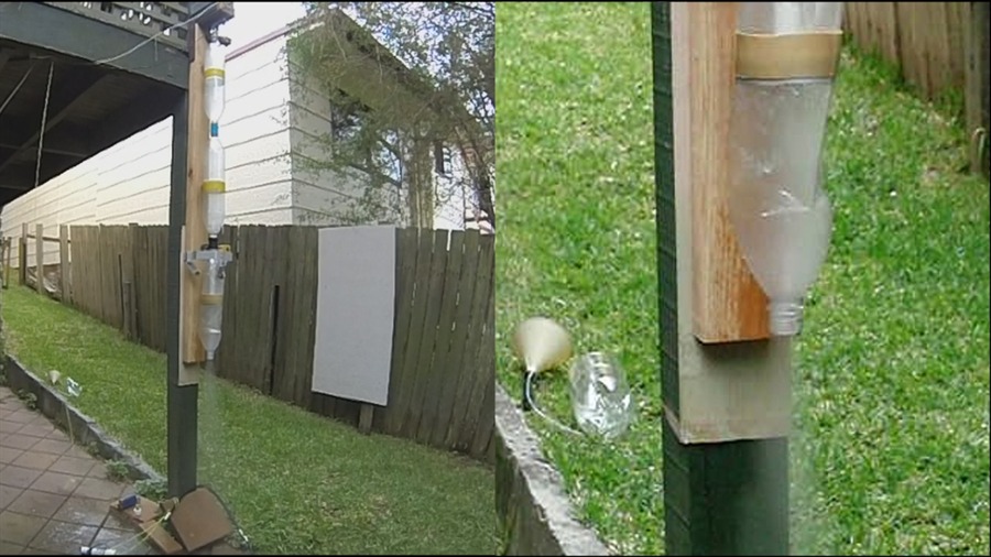
Thrust MeasurementIn order to do some quantitative comparisons we ran a series of tests of the rocket on the load cell to measure the amount of thrust generated. We used our load cell setup for these experiments. Because this dual thrust rocket produces such a wide difference in peak thrust between the two phases we had to reduce the gain on the load cell amplifier so that we wouldn't clip the top of the boost thrust phase but on that setting the amplitude resolution for the sustain phase wasn't very much. At 100psi the boost peak thrust was expected to be around 450 N (101 lbf) and during the sustain phase the peak thrust was expected to be around 20 N (4.5 lbf). So we ran some tests where the boost phase was completely visible and other tests where we turned up the gain to get better amplitude resolution in the sustain phase, but clipped the boost phase. Experiment SetupThe extension tube had a 7mm internal diameter, which was a little on the larger side, so we made a small plastic insert that was glued into the bottom of the tube with a 5mm hole. This way we could compare the performance of the previous spacer design with the new design.
The rocket under test had the following parameters:
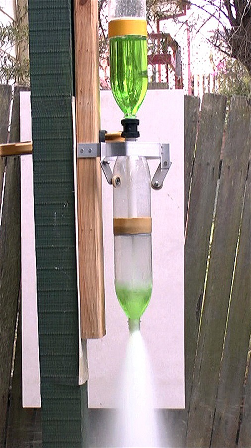
We used 3 video cameras to record each test. The HD camera for real-time view, the GoPro at 240fps to film the entire rocket, and the Exilim FC100 at 210fps to film close-ups of the boost chamber. The release mechanism was a standard Clark Cable-tie launcher in order to use the full 22mm nozzle. It was attached by a string to prevent it from impacting the ground during launch. ResultsPreliminary Tests - 22/12/2013The first tests with the new configuration were carried out just mounted to the test stand (no load cell). These tests were used to check whether the system even worked at all. Two test firings were made with a full 7mm sustain nozzle. These tests were carried out at 100psi (6.9 bar) and 1700mL of water.
Measurement Tests - 23/12/2013The following tests were carried out the next day mounted to the load cell.
Analysis
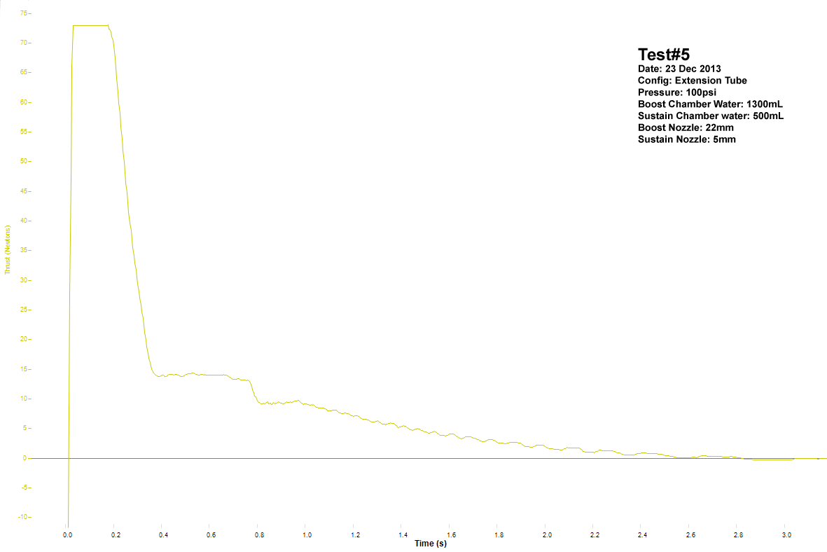
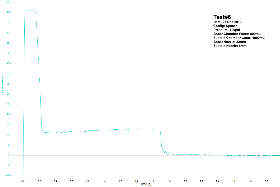
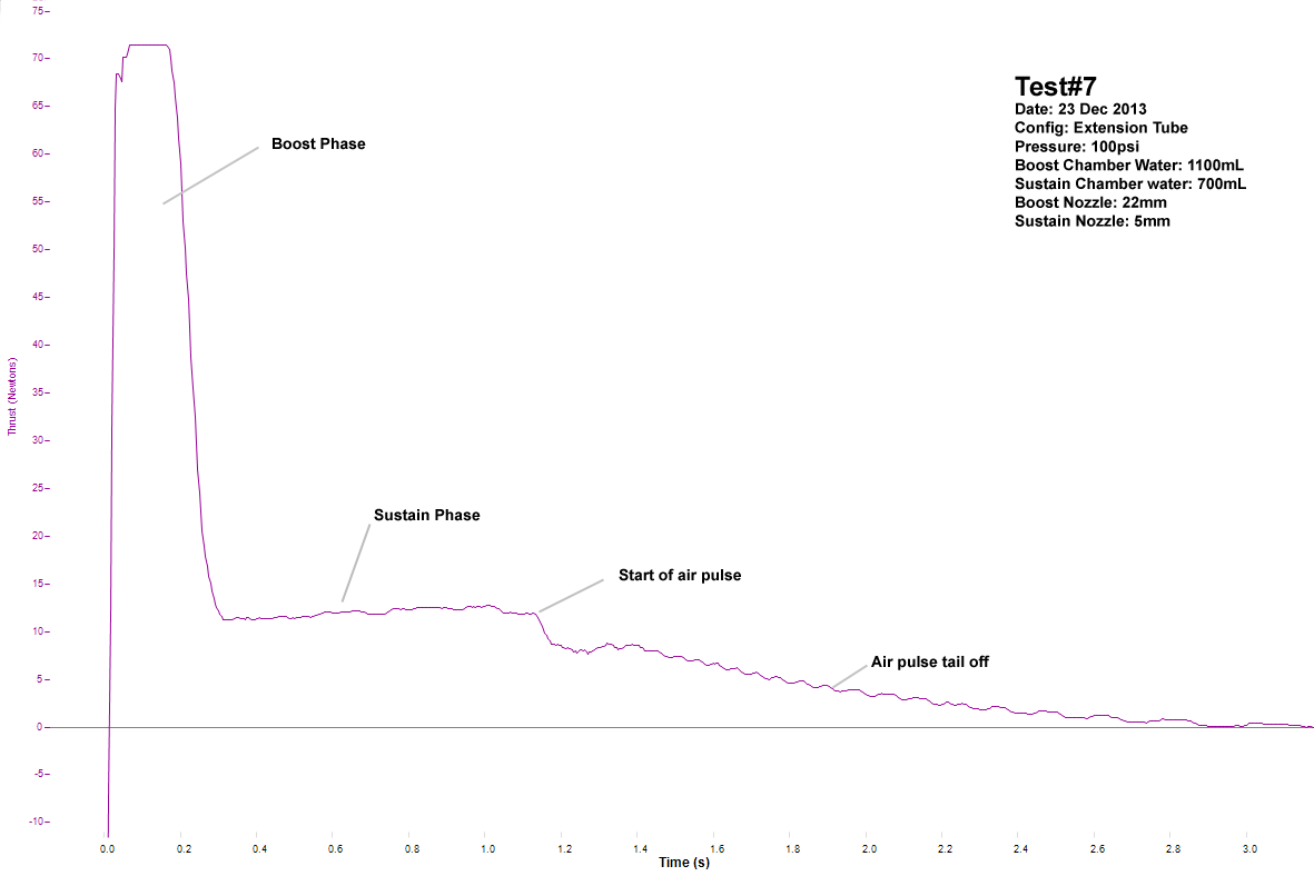
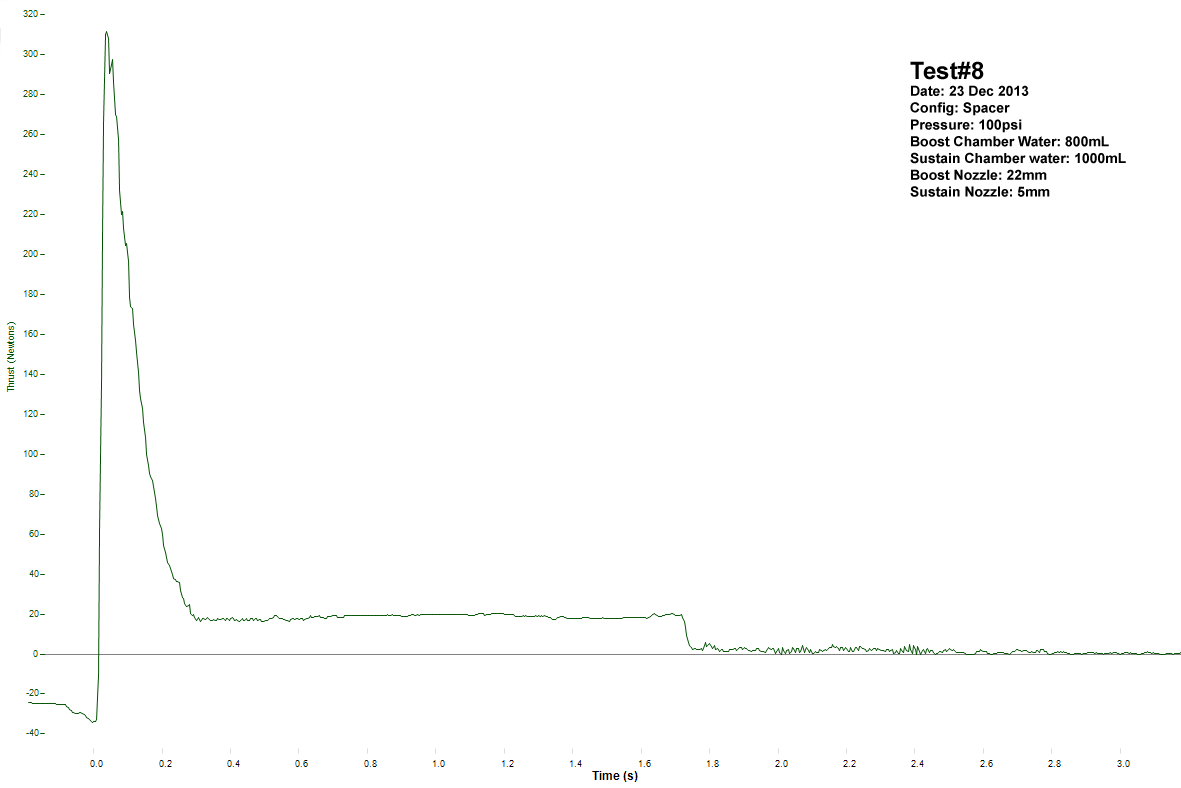
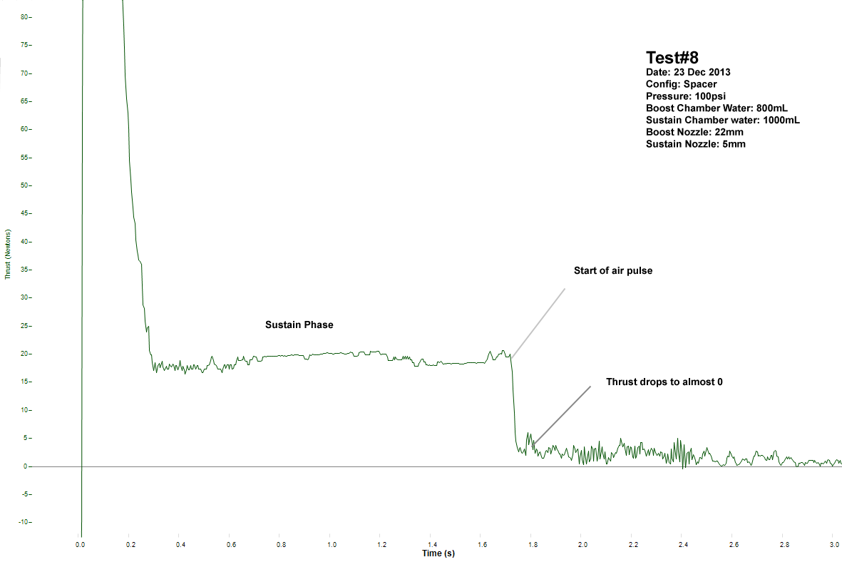
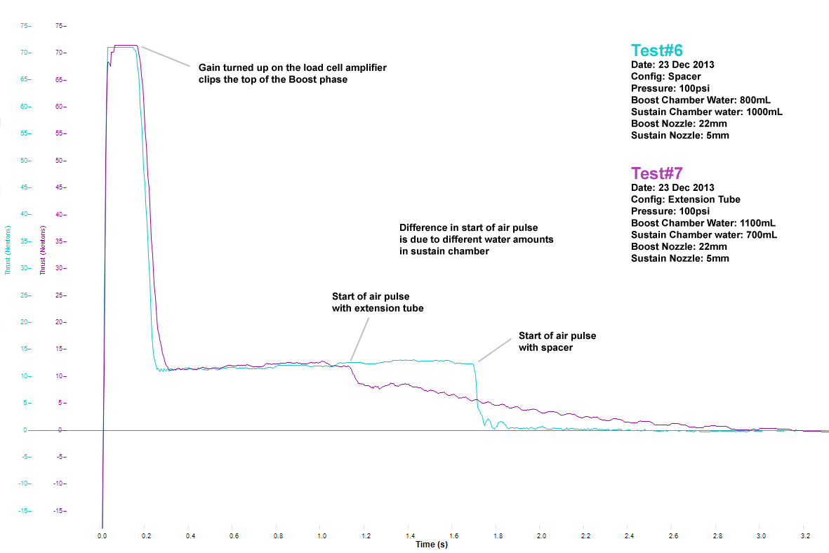
When looking at the spacer thrust curves
from tests #6 and #8 it is evident that
the thrust sharply drops to almost 0 at
the start of the sustain air pulse.
This coincides with the bottle collapse,
and as can be seen in the video that the
air coming out is fairly low velocity.
When we compare this against test #7 we
can see that there is the typical air
pulse tail-off like in normal water
rockets. Test #7 ends the sustain water
phase sooner because there was only
700mL in the sustain chamber compared to
1000mL in test #6. You can also see the difference in that the
boost phase for #7 was about 10% longer compared to #6 because
there was more water in the boost
chamber.
We can
work out that if #7 had 1000mL in the sustain chamber like #6 the end of the
sustain water phase would have been 0.48 seconds later which
almost puts it on par with where it thrust finished for test #6.
Therefore test #7 generated approximately 8 Ns more thrust
during the sustain air phase than in #6. This performance gain
should be measurable in the flight tests.
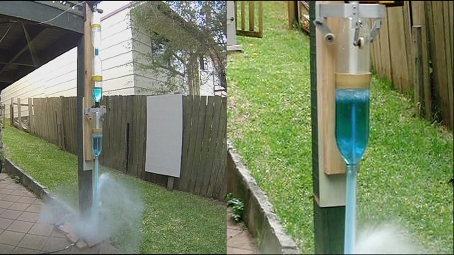
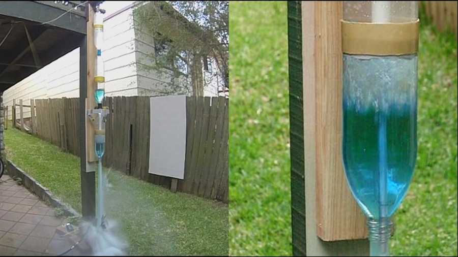
Measuring the thrust difference in the boost phase with and without blow-through is difficult to do with our current setup due to how short the phase is. The boost phase water and air last about ~0.25 seconds. We sample the load cell at only 240Hz and due to the initial launch upward kick, the rocket briefly oscillates on the load cell so we get quite noisy data during the first 0.1seconds of the launch. How effective the no blow-trough boost actually is will be done during flight trials. Here are some video frame captures from the tests:
VideoHere is a highlights video from the tests:
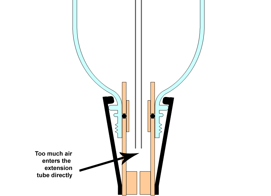
Water Self-LevellingThe one problem encountered during the load cell tests was that the water self-levelling didn't quite work as well as expected. This was traced to pressurised air entering the extension tube directly from the release head, preventing a large enough pressure differential between the sustain chamber and the boost chamber. The pressure differential is important in order to force the water into the sustain chamber. In test #7 we poured some of the water into the sustain chamber beforehand to help distribute the water better. Self-Levelling Tests - 1/1/2014After a short break for Christmas and New Year we followed up with the self-levelling tests.
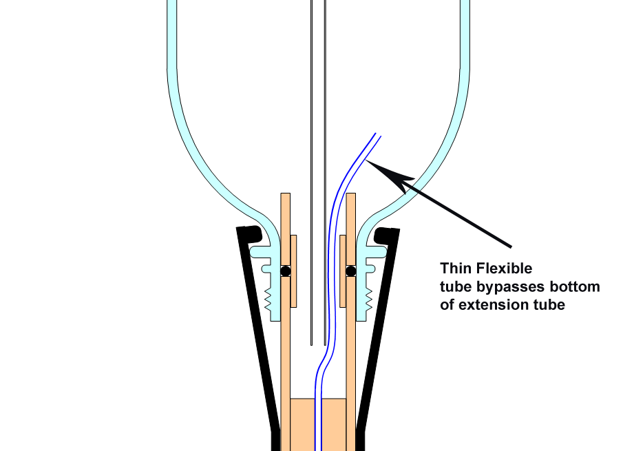
The first attempt at fixing this issue was to add a small flexible tube to the release head that bypassed the bottom of the extension tube so that all the air would go into the boost chamber. The first trial showed that only very little water and air went through the non-return valve mostly because the hole in the extension tube offered much less resistance than the non-return valve. This makes sense because the holes in the non-return valve are small and the o-ring provides some amount of resistance. With most of the water going through the extension tube this meant that most of the water was pushed up into the sustain chamber. We then took a skewer stick and wrapped some electrical tape around it to fit into the extension tube. This acted as a plug to prevent water being forced through it and allow it to flow through the non-return valve. The plug just gets ejected during launch. It could be permanently attached to the inside of the release head. This did the trick and allowed the non-return valve to do its work and correctly self-level the water in the two pressure chambers.
Other Observations
ConclusionsThe extension tube prevents the blow-through effect and allows the water to be ejected cleanly from the boost chamber. The extension tube also prevents the vacuum forming in the boost chamber during the sustain air pulse. The sustain air pulse also generated an additional 8Ns of thrust in these tests. With the extension tube plugged in the launcher, the non-return valve works well to self-level the water in the boost and sustain chambers. Next will come a series of flights with this new arrangement to see how it performs.
|
<< Previous Back to Top Next >>